2002 NISSAN PATROL steering
[x] Cancel search: steeringPage 1 of 311
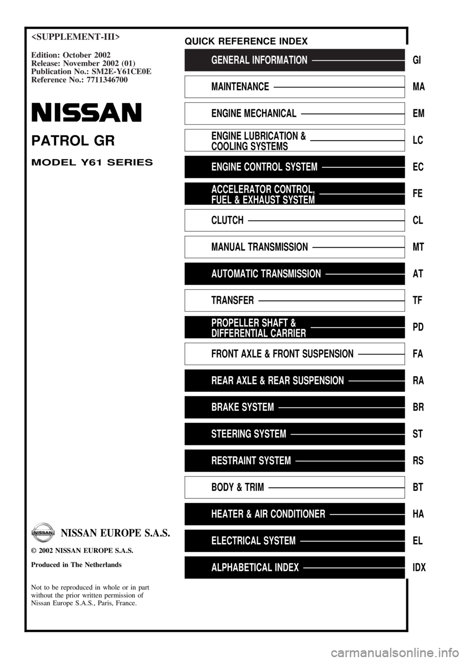
Edition: October 2002
Release: November 2002 (01)
Publication No.: SM2E-Y61CE0E
Reference No.: 7711346700GENERAL INFORMATIONGI
MAINTENANCEMA
ENGINE MECHANICALEM
ENGINE LUBRICATION &
COOLING SYSTEMSLC
ENGINE CONTROL SYSTEMEC
ACCELERATOR CONTROL,
FUEL & EXHAUST SYSTEMFE
CLUTCHCL
MANUAL TRANSMISSIONMT
AUTOMATIC TRANSMISSIONAT
TRANSFERTF
PROPELLER SHAFT &
DIFFERENTIAL CARRIERPD
FRONT AXLE & FRONT SUSPENSIONFA
REAR AXLE & REAR SUSPENSIONRA
BRAKE SYSTEMBR
STEERING SYSTEMST
RESTRAINT SYSTEMRS
BODY & TRIMBT
HEATER & AIR CONDITIONERHA
ELECTRICAL SYSTEMEL
ALPHABETICAL INDEXIDX
PATROL GR
MODEL Y61 SERIES
NISSAN EUROPE S.A.S.
2002 NISSAN EUROPE S.A.S.
Produced in The Netherlands
Not to be reproduced in whole or in part
without the prior written permission of
Nissan Europe S.A.S., Paris, France.
QUICK REFERENCE INDEX
Page 4 of 311
Supplemental Restraint System (SRS) ªAIR
BAGº and ªSEAT BELT PRE-TENSIONERº
The Supplemental Restraint System such as ªAIR BAGº and ªSEAT BELT PRE-TENSIONERº used along
with a seat belt, helps to reduce the risk or severity of injury to the driver and front passenger for certain
types of collision. The SRS system composition which is available to NISSAN MODEL Y61 is as follows (The
composition varies according to the destination and optional equipment.):
+For a frontal collision
The Supplemental Restraint System consists of driver air bag module (located in the center of the
steering wheel), front passenger air bag module (located on the instrument panel on passenger side),
seat belt pre-tensioners, a diagnosis sensor unit, warning lamp, wiring harness and spiral cable.
+For a side collision
The Supplemental Restraint System consists of front side air bag module (located in the outer side of
front seat), satellite sensor, diagnosis sensor unit (one of components of air bags for a frontal collision),
wiring harness, warning lamp (one of components of air bags for a frontal collision).
Information necessary to service the system safely is included in theRS sectionof this Service Manual.
WARNING:
+To avoid rendering the SRS inoperative, which could increase the risk of personal injury or death
in the event of a collision which would result in air bag inflation, all maintenance should be per-
formed by an authorized NISSAN dealer.
+Improper maintenance, including incorrect removal and installation of the SRS, can lead to per-
sonal injury caused by unintentional activation of the system. For removal of Spiral Cable and
Air Bag Module, see the RS section.
+Do not use electrical test equipment on any circuit related to the SRS unless instructed to in this
Service Manual. SRS wiring harnesses can be identified by yellow harness connector.
PRECAUTIONS
AT-3002
Page 47 of 311
ELECTRICAL SYSTEM
SECTION
EL
When you read wiring diagrams:
+Read GI section, ªHOW TO READ WIRING DIAGRAMSº.
When you perform trouble diagnoses, read GI section, ªHOW TO FOLLOW FLOW
CHART IN TROUBLE DIAGNOSESº and ªHOW TO PERFORM EFFICIENT DIAGNOSIS
FOR AN ELECTRICAL INCIDENTº.
+Check for any service bulletins before servicing the vehicle.
MODIFICATION NOTICE:
+Combination meter has been changed.
+Wiring Diagram has been changed.
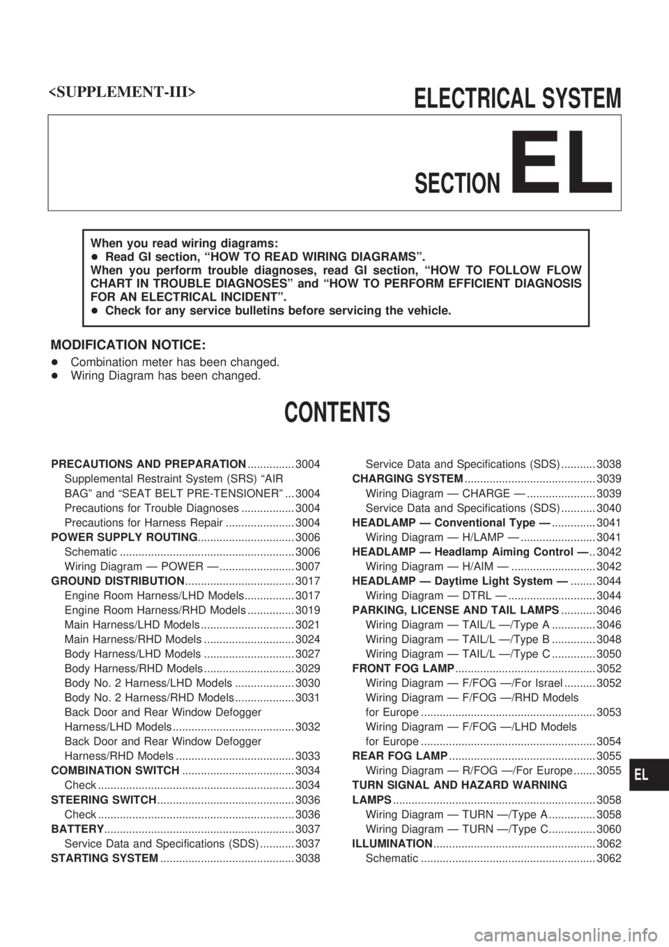
CONTENTS
PRECAUTIONS AND PREPARATION............... 3004
Supplemental Restraint System (SRS) ªAIR
BAGº and ªSEAT BELT PRE-TENSIONERº ... 3004
Precautions for Trouble Diagnoses ................. 3004
Precautions for Harness Repair ...................... 3004
POWER SUPPLY ROUTING............................... 3006
Schematic ........................................................ 3006
Wiring Diagram Ð POWER Ð ........................ 3007
GROUND DISTRIBUTION................................... 3017
Engine Room Harness/LHD Models................ 3017
Engine Room Harness/RHD Models ............... 3019
Main Harness/LHD Models .............................. 3021
Main Harness/RHD Models ............................. 3024
Body Harness/LHD Models ............................. 3027
Body Harness/RHD Models ............................. 3029
Body No. 2 Harness/LHD Models ................... 3030
Body No. 2 Harness/RHD Models ................... 3031
Back Door and Rear Window Defogger
Harness/LHD Models ....................................... 3032
Back Door and Rear Window Defogger
Harness/RHD Models ...................................... 3033
COMBINATION SWITCH.................................... 3034
Check ............................................................... 3034
STEERING SWITCH............................................ 3036
Check ............................................................... 3036
BATTERY............................................................. 3037
Service Data and Specifications (SDS) ........... 3037
STARTING SYSTEM........................................... 3038Service Data and Specifications (SDS) ........... 3038
CHARGING SYSTEM.......................................... 3039
Wiring Diagram Ð CHARGE Ð ...................... 3039
Service Data and Specifications (SDS) ........... 3040
HEADLAMP Ð Conventional Type Ð.............. 3041
Wiring Diagram Ð H/LAMP Ð ........................ 3041
HEADLAMP Ð Headlamp Aiming Control Ð.. 3042
Wiring Diagram Ð H/AIM Ð ........................... 3042
HEADLAMP Ð Daytime Light System Ð........ 3044
Wiring Diagram Ð DTRL Ð ............................ 3044
PARKING, LICENSE AND TAIL LAMPS........... 3046
Wiring Diagram Ð TAIL/L Ð/Type A .............. 3046
Wiring Diagram Ð TAIL/L Ð/Type B .............. 3048
Wiring Diagram Ð TAIL/L Ð/Type C .............. 3050
FRONT FOG LAMP............................................. 3052
Wiring Diagram Ð F/FOG Ð/For Israel .......... 3052
Wiring Diagram Ð F/FOG Ð/RHD Models
for Europe ........................................................ 3053
Wiring Diagram Ð F/FOG Ð/LHD Models
for Europe ........................................................ 3054
REAR FOG LAMP............................................... 3055
Wiring Diagram Ð R/FOG Ð/For Europe ....... 3055
TURN SIGNAL AND HAZARD WARNING
LAMPS................................................................. 3058
Wiring Diagram Ð TURN Ð/Type A ............... 3058
Wiring Diagram Ð TURN Ð/Type C............... 3060
ILLUMINATION.................................................... 3062
Schematic ........................................................ 3062
EL
Page 50 of 311
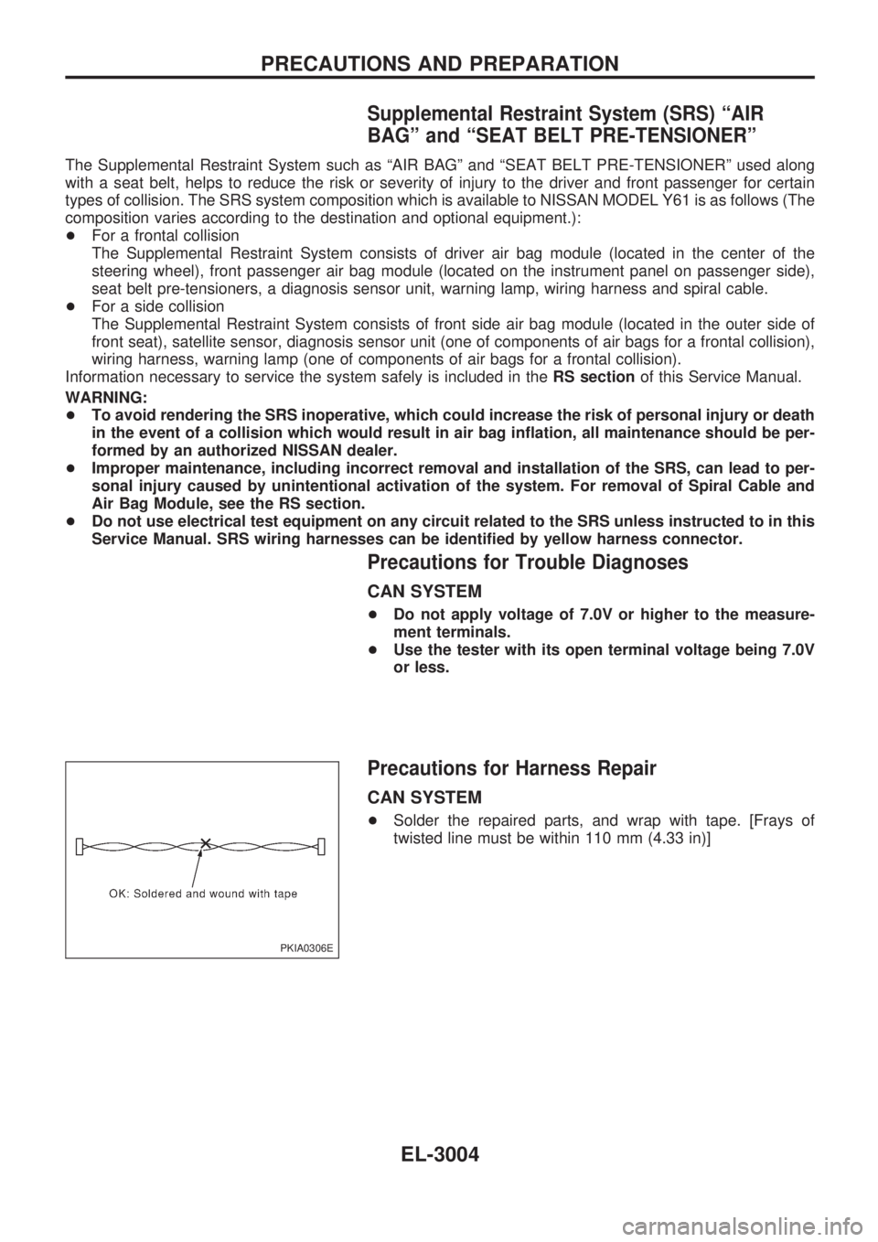
Supplemental Restraint System (SRS) ªAIR
BAGº and ªSEAT BELT PRE-TENSIONERº
The Supplemental Restraint System such as ªAIR BAGº and ªSEAT BELT PRE-TENSIONERº used along
with a seat belt, helps to reduce the risk or severity of injury to the driver and front passenger for certain
types of collision. The SRS system composition which is available to NISSAN MODEL Y61 is as follows (The
composition varies according to the destination and optional equipment.):
+For a frontal collision
The Supplemental Restraint System consists of driver air bag module (located in the center of the
steering wheel), front passenger air bag module (located on the instrument panel on passenger side),
seat belt pre-tensioners, a diagnosis sensor unit, warning lamp, wiring harness and spiral cable.
+For a side collision
The Supplemental Restraint System consists of front side air bag module (located in the outer side of
front seat), satellite sensor, diagnosis sensor unit (one of components of air bags for a frontal collision),
wiring harness, warning lamp (one of components of air bags for a frontal collision).
Information necessary to service the system safely is included in theRS sectionof this Service Manual.
WARNING:
+To avoid rendering the SRS inoperative, which could increase the risk of personal injury or death
in the event of a collision which would result in air bag inflation, all maintenance should be per-
formed by an authorized NISSAN dealer.
+Improper maintenance, including incorrect removal and installation of the SRS, can lead to per-
sonal injury caused by unintentional activation of the system. For removal of Spiral Cable and
Air Bag Module, see the RS section.
+Do not use electrical test equipment on any circuit related to the SRS unless instructed to in this
Service Manual. SRS wiring harnesses can be identified by yellow harness connector.
Precautions for Trouble Diagnoses
CAN SYSTEM
+Do not apply voltage of 7.0V or higher to the measure-
ment terminals.
+Use the tester with its open terminal voltage being 7.0V
or less.
Precautions for Harness Repair
CAN SYSTEM
+Solder the repaired parts, and wrap with tape. [Frays of
twisted line must be within 110 mm (4.33 in)]
PKIA0306E
PRECAUTIONS AND PREPARATION
EL-3004
Page 82 of 311

Check
WITH ASCD AND AUDIO SWITCH
CEL310M
STEERING SWITCH
EL-3036
Page 257 of 311
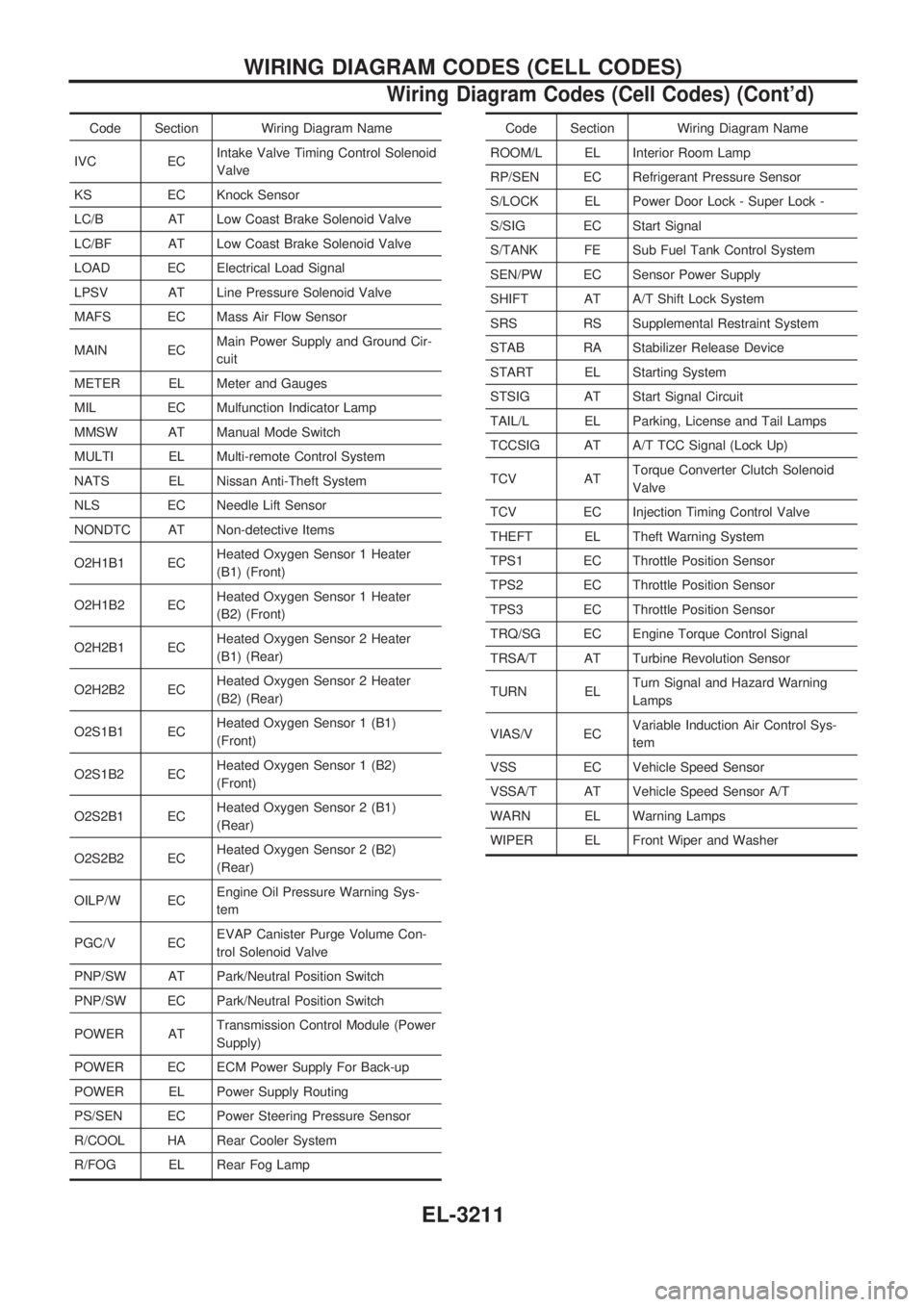
Code Section Wiring Diagram Name
IVC ECIntake Valve Timing Control Solenoid
Valve
KS EC Knock Sensor
LC/B AT Low Coast Brake Solenoid Valve
LC/BF AT Low Coast Brake Solenoid Valve
LOAD EC Electrical Load Signal
LPSV AT Line Pressure Solenoid Valve
MAFS EC Mass Air Flow Sensor
MAIN ECMain Power Supply and Ground Cir-
cuit
METER EL Meter and Gauges
MIL EC Mulfunction Indicator Lamp
MMSW AT Manual Mode Switch
MULTI EL Multi-remote Control System
NATS EL Nissan Anti-Theft System
NLS EC Needle Lift Sensor
NONDTC AT Non-detective Items
O2H1B1 ECHeated Oxygen Sensor 1 Heater
(B1) (Front)
O2H1B2 ECHeated Oxygen Sensor 1 Heater
(B2) (Front)
O2H2B1 ECHeated Oxygen Sensor 2 Heater
(B1) (Rear)
O2H2B2 ECHeated Oxygen Sensor 2 Heater
(B2) (Rear)
O2S1B1 ECHeated Oxygen Sensor 1 (B1)
(Front)
O2S1B2 ECHeated Oxygen Sensor 1 (B2)
(Front)
O2S2B1 ECHeated Oxygen Sensor 2 (B1)
(Rear)
O2S2B2 ECHeated Oxygen Sensor 2 (B2)
(Rear)
OILP/W ECEngine Oil Pressure Warning Sys-
tem
PGC/V ECEVAP Canister Purge Volume Con-
trol Solenoid Valve
PNP/SW AT Park/Neutral Position Switch
PNP/SW EC Park/Neutral Position Switch
POWER ATTransmission Control Module (Power
Supply)
POWER EC ECM Power Supply For Back-up
POWER EL Power Supply Routing
PS/SEN EC Power Steering Pressure Sensor
R/COOL HA Rear Cooler System
R/FOG EL Rear Fog LampCode Section Wiring Diagram Name
ROOM/L EL Interior Room Lamp
RP/SEN EC Refrigerant Pressure Sensor
S/LOCK EL Power Door Lock - Super Lock -
S/SIG EC Start Signal
S/TANK FE Sub Fuel Tank Control System
SEN/PW EC Sensor Power Supply
SHIFT AT A/T Shift Lock System
SRS RS Supplemental Restraint System
STAB RA Stabilizer Release Device
START EL Starting System
STSIG AT Start Signal Circuit
TAIL/L EL Parking, License and Tail Lamps
TCCSIG AT A/T TCC Signal (Lock Up)
TCV ATTorque Converter Clutch Solenoid
Valve
TCV EC Injection Timing Control Valve
THEFT EL Theft Warning System
TPS1 EC Throttle Position Sensor
TPS2 EC Throttle Position Sensor
TPS3 EC Throttle Position Sensor
TRQ/SG EC Engine Torque Control Signal
TRSA/T AT Turbine Revolution Sensor
TURN ELTurn Signal and Hazard Warning
Lamps
VIAS/V ECVariable Induction Air Control Sys-
tem
VSS EC Vehicle Speed Sensor
VSSA/T AT Vehicle Speed Sensor A/T
WARN EL Warning Lamps
WIPER EL Front Wiper and Washer
WIRING DIAGRAM CODES (CELL CODES)
Wiring Diagram Codes (Cell Codes) (Cont'd)
EL-3211
Page 272 of 311
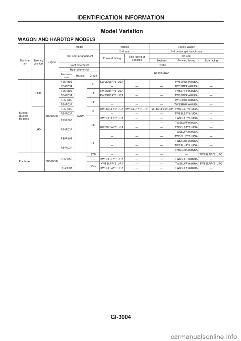
Model Variation
WAGON AND HARDTOP MODELS
Destina-
tionSteering
positionEngineModel Hardtop Station Wagon
Rear seat arrangement2nd seat 2nd center split bench seat
Forward facingSide facing or
Seatless3rd seat
Seatless Forward facing Side facing
Front differential H233B
Rear differential
H233B/H260
Transmis-
sionTransfer Grade
Europe
(Except
for Israel)RHD
ZD30DDTiFS5R50B
TX12ASKWSSREFY61UEA Ð Ð TWSSREFY61UEA Ð
RE4R03A Ð Ð Ð TWSSREAY61UEA Ð
FS5R50B
SEKWSSRFFY61UEA Ð Ð TWSSRFFY61UEA Ð
RE4R03A KWSSRFAY61UEA Ð Ð TWSSRFAY61UEA Ð
FS5R50B
SEÐ Ð Ð TWSSRHFY61UEA Ð
RE4R03A Ð Ð Ð TWSSRHAY61UEA Ð
LHDFS5R50B
SKWSSLEFY61UGA KWSSLEFY61USP TWSSLEFY61USP TWSSLEFY61UGA Ð
RE4R03A Ð Ð Ð TWSSLEAY61UGA Ð
FS5R50B
SEKWSSLFFY61UGA Ð Ð TWSSLFFY61UGA Ð
Ð Ð Ð TWSSLFFY61USA Ð
RE4R03AKWSSLFAY61UGA Ð Ð TWSSLFAY61UGA Ð
Ð Ð Ð TWSSLFAY61USA Ð
FS5R50B
SEÐ Ð Ð TWSSLHFY61UGA Ð
Ð Ð Ð TWSSLHFY61USA Ð
RE4R03AÐ Ð Ð TWSSLHAY61UGA Ð
Ð Ð Ð TWSSLHAY61USA Ð
For Israel ZD30DDTiFS5R05BSTDÐÐÐÐTWSSLAFY61URQ
GL KWSSLEFY61URA Ð Ð TWSSLEFY61URA Ð
SGLKWSSLFFY61URA Ð Ð TWSSLFFY61URA TWSSLFFY61URQ
RE4R03A KWSSLFAY61URA Ð Ð TWSSLFAY61URA Ð
IDENTIFICATION INFORMATION
GI-3004
Page 278 of 311
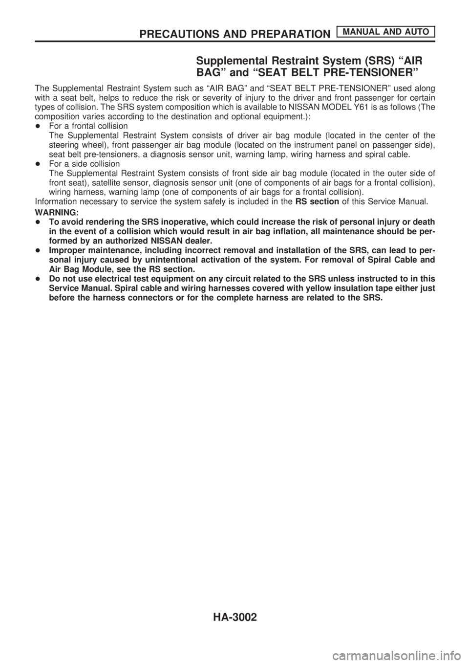
Supplemental Restraint System (SRS) ªAIR
BAGº and ªSEAT BELT PRE-TENSIONERº
The Supplemental Restraint System such as ªAIR BAGº and ªSEAT BELT PRE-TENSIONERº used along
with a seat belt, helps to reduce the risk or severity of injury to the driver and front passenger for certain
types of collision. The SRS system composition which is available to NISSAN MODEL Y61 is as follows (The
composition varies according to the destination and optional equipment.):
+For a frontal collision
The Supplemental Restraint System consists of driver air bag module (located in the center of the
steering wheel), front passenger air bag module (located on the instrument panel on passenger side),
seat belt pre-tensioners, a diagnosis sensor unit, warning lamp, wiring harness and spiral cable.
+For a side collision
The Supplemental Restraint System consists of front side air bag module (located in the outer side of
front seat), satellite sensor, diagnosis sensor unit (one of components of air bags for a frontal collision),
wiring harness, warning lamp (one of components of air bags for a frontal collision).
Information necessary to service the system safely is included in theRS sectionof this Service Manual.
WARNING:
+To avoid rendering the SRS inoperative, which could increase the risk of personal injury or death
in the event of a collision which would result in air bag inflation, all maintenance should be per-
formed by an authorized NISSAN dealer.
+Improper maintenance, including incorrect removal and installation of the SRS, can lead to per-
sonal injury caused by unintentional activation of the system. For removal of Spiral Cable and
Air Bag Module, see the RS section.
+Do not use electrical test equipment on any circuit related to the SRS unless instructed to in this
Service Manual. Spiral cable and wiring harnesses covered with yellow insulation tape either just
before the harness connectors or for the complete harness are related to the SRS.
PRECAUTIONS AND PREPARATIONMANUAL AND AUTO
HA-3002