Page 196 of 311
TEL588M
MULTI-REMOTE CONTROL SYSTEM
Wiring Diagram Ð MULTI Ð/LHD Models with
Theft Warning System (Cont'd)
EL-3150
Page 197 of 311
TEL589M
MULTI-REMOTE CONTROL SYSTEM
Wiring Diagram Ð MULTI Ð/LHD Models with
Theft Warning System (Cont'd)
EL-3151
Page 198 of 311
TEL799M
MULTI-REMOTE CONTROL SYSTEM
Wiring Diagram Ð MULTI Ð/LHD Models with
Theft Warning System (Cont'd)
EL-3152
Page 199 of 311
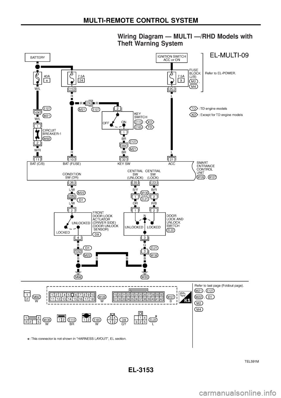
Wiring Diagram Ð MULTI Ð/RHD Models with
Theft Warning System
TEL591M
MULTI-REMOTE CONTROL SYSTEM
EL-3153
Page 200 of 311
TEL592M
MULTI-REMOTE CONTROL SYSTEM
Wiring Diagram Ð MULTI Ð/RHD Models with
Theft Warning System (Cont'd)
EL-3154
Page 201 of 311
TEL800M
MULTI-REMOTE CONTROL SYSTEM
Wiring Diagram Ð MULTI Ð/RHD Models with
Theft Warning System (Cont'd)
EL-3155
Page 257 of 311
Code Section Wiring Diagram Name
IVC ECIntake Valve Timing Control Solenoid
Valve
KS EC Knock Sensor
LC/B AT Low Coast Brake Solenoid Valve
LC/BF AT Low Coast Brake Solenoid Valve
LOAD EC Electrical Load Signal
LPSV AT Line Pressure Solenoid Valve
MAFS EC Mass Air Flow Sensor
MAIN ECMain Power Supply and Ground Cir-
cuit
METER EL Meter and Gauges
MIL EC Mulfunction Indicator Lamp
MMSW AT Manual Mode Switch
MULTI EL Multi-remote Control System
NATS EL Nissan Anti-Theft System
NLS EC Needle Lift Sensor
NONDTC AT Non-detective Items
O2H1B1 ECHeated Oxygen Sensor 1 Heater
(B1) (Front)
O2H1B2 ECHeated Oxygen Sensor 1 Heater
(B2) (Front)
O2H2B1 ECHeated Oxygen Sensor 2 Heater
(B1) (Rear)
O2H2B2 ECHeated Oxygen Sensor 2 Heater
(B2) (Rear)
O2S1B1 ECHeated Oxygen Sensor 1 (B1)
(Front)
O2S1B2 ECHeated Oxygen Sensor 1 (B2)
(Front)
O2S2B1 ECHeated Oxygen Sensor 2 (B1)
(Rear)
O2S2B2 ECHeated Oxygen Sensor 2 (B2)
(Rear)
OILP/W ECEngine Oil Pressure Warning Sys-
tem
PGC/V ECEVAP Canister Purge Volume Con-
trol Solenoid Valve
PNP/SW AT Park/Neutral Position Switch
PNP/SW EC Park/Neutral Position Switch
POWER ATTransmission Control Module (Power
Supply)
POWER EC ECM Power Supply For Back-up
POWER EL Power Supply Routing
PS/SEN EC Power Steering Pressure Sensor
R/COOL HA Rear Cooler System
R/FOG EL Rear Fog LampCode Section Wiring Diagram Name
ROOM/L EL Interior Room Lamp
RP/SEN EC Refrigerant Pressure Sensor
S/LOCK EL Power Door Lock - Super Lock -
S/SIG EC Start Signal
S/TANK FE Sub Fuel Tank Control System
SEN/PW EC Sensor Power Supply
SHIFT AT A/T Shift Lock System
SRS RS Supplemental Restraint System
STAB RA Stabilizer Release Device
START EL Starting System
STSIG AT Start Signal Circuit
TAIL/L EL Parking, License and Tail Lamps
TCCSIG AT A/T TCC Signal (Lock Up)
TCV ATTorque Converter Clutch Solenoid
Valve
TCV EC Injection Timing Control Valve
THEFT EL Theft Warning System
TPS1 EC Throttle Position Sensor
TPS2 EC Throttle Position Sensor
TPS3 EC Throttle Position Sensor
TRQ/SG EC Engine Torque Control Signal
TRSA/T AT Turbine Revolution Sensor
TURN ELTurn Signal and Hazard Warning
Lamps
VIAS/V ECVariable Induction Air Control Sys-
tem
VSS EC Vehicle Speed Sensor
VSSA/T AT Vehicle Speed Sensor A/T
WARN EL Warning Lamps
WIPER EL Front Wiper and Washer
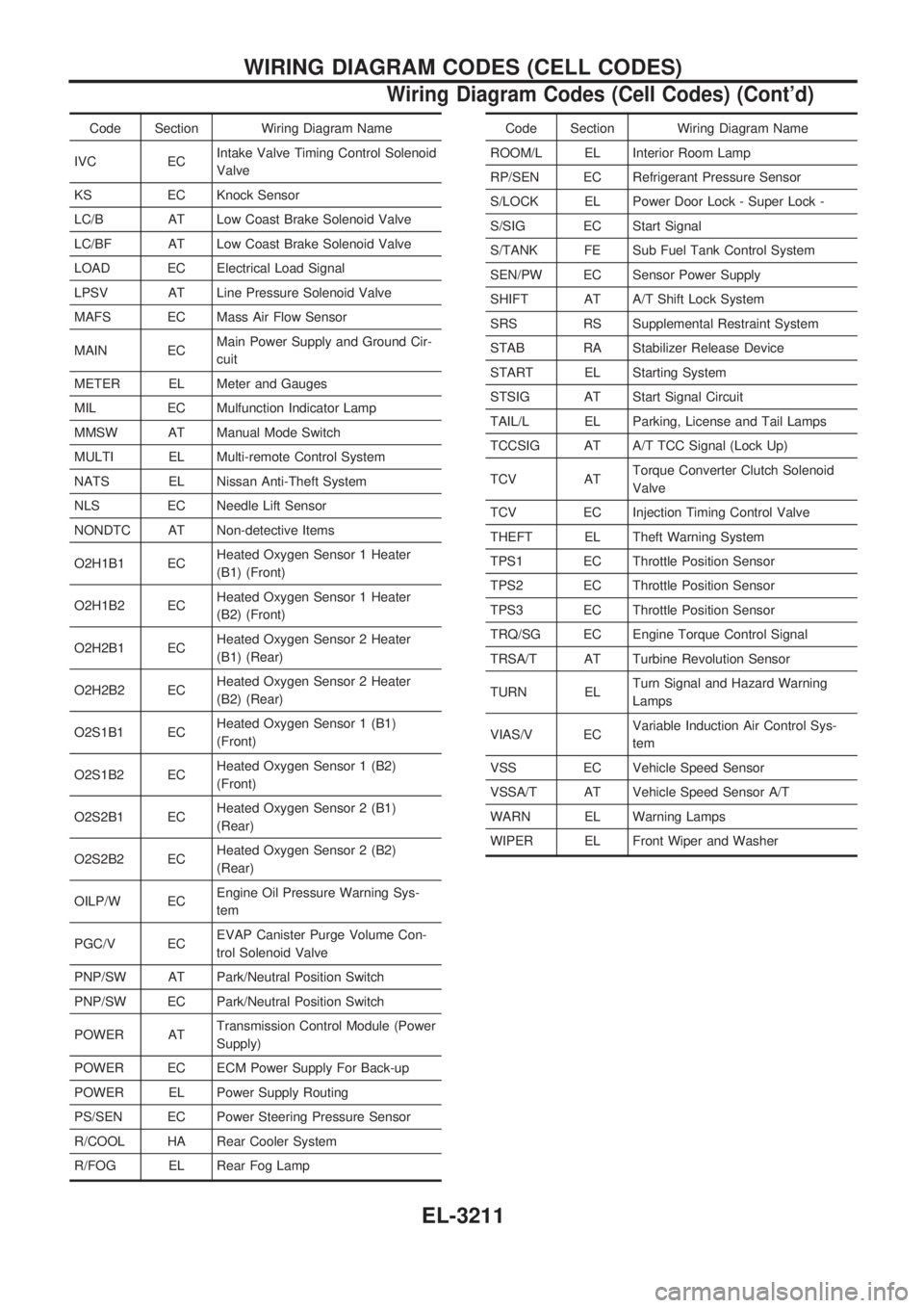
WIRING DIAGRAM CODES (CELL CODES)
Wiring Diagram Codes (Cell Codes) (Cont'd)
EL-3211
Page 270 of 311
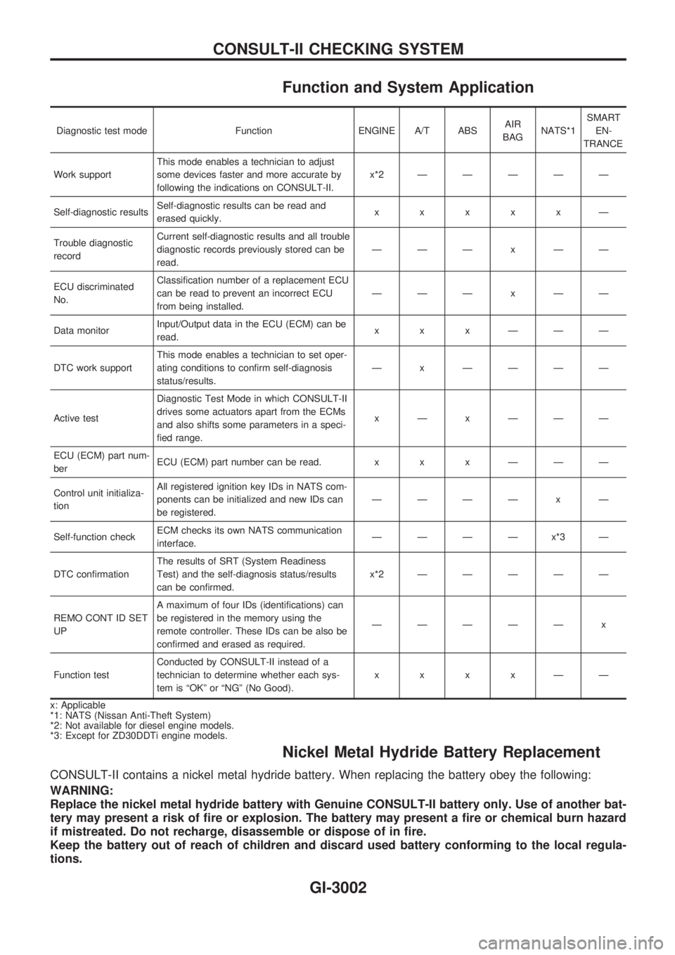
Function and System Application
Diagnostic test mode Function ENGINE A/T ABSAIR
BAGNATS*1SMART
EN-
TRANCE
Work supportThis mode enables a technician to adjust
some devices faster and more accurate by
following the indications on CONSULT-II.x*2ÐÐÐÐÐ
Self-diagnostic resultsSelf-diagnostic results can be read and
erased quickly.xxxxxÐ
Trouble diagnostic
recordCurrent self-diagnostic results and all trouble
diagnostic records previously stored can be
read.ÐÐÐxÐÐ
ECU discriminated
No.Classification number of a replacement ECU
can be read to prevent an incorrect ECU
from being installed.ÐÐÐxÐÐ
Data monitorInput/Output data in the ECU (ECM) can be
read.xxxÐÐÐ
DTC work supportThis mode enables a technician to set oper-
ating conditions to confirm self-diagnosis
status/results.Ð x ÐÐÐÐ
Active testDiagnostic Test Mode in which CONSULT-II
drives some actuators apart from the ECMs
and also shifts some parameters in a speci-
fied range.xÐxÐÐÐ
ECU (ECM) part num-
berECU (ECM) part number can be read. x x x Ð Ð Ð
Control unit initializa-
tionAll registered ignition key IDs in NATS com-
ponents can be initialized and new IDs can
be registered.ÐÐÐÐ x Ð
Self-function checkECM checks its own NATS communication
interface.ÐÐÐÐx*3Ð
DTC confirmationThe results of SRT (System Readiness
Test) and the self-diagnosis status/results
can be confirmed.x*2ÐÐÐÐÐ
REMO CONT ID SET
UPA maximum of four IDs (identifications) can
be registered in the memory using the
remote controller. These IDs can be also be
confirmed and erased as required.ÐÐÐÐÐ x
Function testConducted by CONSULT-II instead of a
technician to determine whether each sys-
tem is ªOKº or ªNGº (No Good).xxxxÐÐ
x: Applicable
*1: NATS (Nissan Anti-Theft System)
*2: Not available for diesel engine models.
*3: Except for ZD30DDTi engine models.
Nickel Metal Hydride Battery Replacement
CONSULT-II contains a nickel metal hydride battery. When replacing the battery obey the following:
WARNING:
Replace the nickel metal hydride battery with Genuine CONSULT-II battery only. Use of another bat-
tery may present a risk of fire or explosion. The battery may present a fire or chemical burn hazard
if mistreated. Do not recharge, disassemble or dispose of in fire.
Keep the battery out of reach of children and discard used battery conforming to the local regula-
tions.
CONSULT-II CHECKING SYSTEM
GI-3002