2002 NISSAN MAXIMA ECU
[x] Cancel search: ECUPage 94 of 247

Recommended battery: Sanyo CR2025 or
equivalent
Make sure that theÅside faces the
bottom case.
3. Close the lid securely.
4. Push the keyfob button two or three times
to check its operation.
See your NISSAN dealer if you need any
assistance for replacement.
If the battery is removed for any reason
other than replacement, perform step 4
above.
IBe careful not to touch a circuit board
and a battery terminal.
IAn improperly disposed battery can
harm the environment. Always confirm
local regulations for battery disposal.
IThe keyfob is water-resistant; however,
if it does get wet, immediately wipe com-
pletely dry.
IWhen changing batteries, do not let dust
or oil get on the keyfob.
FCC Notice:
Changes or modifications not expressly
approved by the manufacturer compliancecould void the user's authority to operate
the equipment. This device complies with
Part 15 of the FCC Rules and RSS-210 of
Industry Canada. Operation is subject to
the following two conditions: (1) This de-
vice may not cause harmful interference,
and (2) this device must accept any inter-
ference received, including interference
that may cause undesired operation of the
device.
Pre-driving checks and adjustments
3-9
Z
01.9.21/A33-D/V5.0
X
Page 96 of 247

OPENER OPERATIONThe trunk lid release button is located under
the driver's arm rest.
To open the trunk lid, pull the release button.
To close, push the trunk lid down securely.
Cancel leverWhen the lever is in the cancel position, the
trunk lid cannot be opened with the trunk lid
release button. It can be opened only with the
master key.
KEY OPERATIONTo open the trunk lid, turn the key clockwise.
To close, lower and push the trunk lid down
securely.
SPA0985
SPA0095
SPA0992
Pre-driving checks and adjustments
3-11
Z
01.9.21/A33-D/V5.0
X
Page 97 of 247

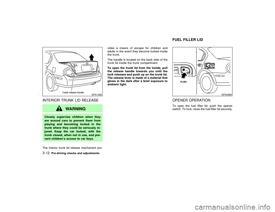
INTERIOR TRUNK LID RELEASE
WARNING
Closely supervise children when they
are around cars to prevent them from
playing and becoming locked in the
trunk where they could be seriously in-
jured. Keep the car locked, with the
trunk closed, when not in use, and pre-
vent children's access to car keys.
The interior trunk lid release mechanism pro-vides a means of escape for children and
adults in the event they become locked inside
the trunk.
The handle is located on the back side of the
trunk lid inside the trunk compartment.
To open the trunk lid from the inside, pull
the release handle towards you until the
lock releases and push up on the trunk lid.
The release lever is made of a material that
glows in the dark after a brief exposure to
ambient light.
OPENER OPERATIONTo open the fuel filler lid, push the opener
switch. To lock, close the fuel filler lid securely.
SPA1382
SPA0986
FUEL FILLER LID
3-12
Pre-driving checks and adjustments
Z
01.9.21/A33-D/V5.0
X
Page 102 of 247

PROCEDURE FOR STORING
MEMORYTwo positions can be stored in the automatic
driver's seat positioner memory.Follow these
procedures to use the memory system.
1. A/T models:
Set the automatic transmission selector
lever to the P (Park) position.
M/T models:
Apply the parking brake securely when the
vehicle is stopped.
2. Turn the ignition ON.
3. Adjust the driver's seat and steering column
to the desired positions by manually oper-
ating each adjusting switch. For additional
information, see ªSeatsº in the ª1. Seats,
restraints and supplemental air bag sys-
temsº section and ªSteering wheelº earlier
in this section.During this step, do not turn the ignition to
any positions other than ON.
4. Push the SET switch and, within 5 seconds,
push the memory switch 1 or 2 fully for at
least 1 second.
The indicator light for the pushed memory
switch will come on and stay on for approxi-
mately 5 seconds after pushing the switch.
After the indicator light goes off, the se-
lected positions are stored in the selected
memory (1 or 2).
If memory is stored in the same memory
switch, the previous memory will be de-
leted.
Confirming memory storageITurn the ignition ON and push the SET
switch. If the main memory has not been
stored, the indicator light will come on for
approximately 0.5 seconds. When the
memory has stored the position, the indica-
tor light will stay on for approximately 5
seconds.
IIf the battery cable is disconnected, or if the
fuse blows, the memory will be canceled. In
such a case, reset the desired positions
using the following procedures.
1. Open and close the driver's door more than
SPA1385
Pre-driving checks and adjustments
3-17
Z
01.9.21/A33-D/V5.0
X
Page 103 of 247

two times with the ignition key in the LOCK
position.
2. Reset the desired position using the previ-
ous procedure.
Selecting the memorized position1. A/T models:
Set the automatic transmission selector le-
ver to the P (Park) position.
M/T models:
Apply the parking brake securely when the
vehicle is stopped.
2. Turn the ignition ON.
3. Push the memory switch 1 or 2 fully for at
least 1 second.
The driver's seat will move to the memo-
rized position with the indicator light flash-
ing. Then the light will stay on for approxi-
mately 5 seconds.
When memory switch 1 or 2 is pushed with the
driver's door open and then the key inserted
into the ignition switch within approximately 1
minute, the driver's seat will move to the
memorized position. Ð A/T models only
System operationThe automatic drive positioner system will not
work or will stop operating under the following
conditions:
Iwhen the vehicle speed is above 4 MPH (7
km/h).
Iwhen any two or more of the memory
switches are simultaneously pressed while
the automatic drive positioner is operating.
Iwhen the adjusting switch for the driver's
seat is turned on while the automatic drive
positioner is operating.
Iwhen the cancel switch located on the
instrument panel is pushed to cancel.
Iwhen the memory switch 1 or 2 is not
pushed for at least 1 second.
Iwhen the seat has already been moved to
the memorized position.
Iwhen no seat position is stored in the
memory switch.
Iwhen the parking brake is not applied. Ð
M/T models
Iwhen the vehicle speed is above 4 MPH (7
km/h) while the parking brake is applied. Ð
M/T models
To restart the drive positioner system,move the parking brake to off and on.
Iwhen the engine is started while moving the
automatic drive positioner. Ð M/T models
3-18
Pre-driving checks and adjustments
Z
01.9.21/A33-D/V5.0
X
Page 156 of 247

chains, make sure they are of proper size
for the tires on your vehicle and are in-
stalled according to the chain manufactur-
er's suggestions.Use only SAE Class S
chains.Other types may damage your
vehicle. Use chain tensioners when recom-
mended by the tire chain manufacturer to
ensure a tight fit. Loose end links of the tire
chain must be secured or removed to pre-
vent the possibility of whipping action dam-
age to the fenders or underbody. If pos-
sible, avoid fully loading your vehicle when
using tire chains. In addition, drive at a
reduced speed. Otherwise, your vehicle
may be damaged and/or vehicle handling
and performance may be adversely af-
fected.
Never install tire chains on a T-type spare
tire. Do not use tire chains on dry roads.
SPECIAL WINTER EQUIPMENTIt is recommended that the following items be
carried in the vehicle during winter:
Ia scraper and stiff-bristled brush to remove
ice and snow from the windows and wiper
blades.
Ia sturdy, flat board to be placed under the
jack to give it firm support.Ia shovel to dig the vehicle out of snow-
drifts.
Iextra window washer fluid to refill the res-
ervoir tank.
DRIVING ON SNOW OR ICE
WARNING
IWet ice (32ÉF, 0ÉC and freezing rain),
very cold snow or ice can be slick and
very hard to drive on. The vehicle will
have a lot less traction or grip under
these conditions. Try to avoid driving
on wet ice until the road is salted or
sanded.
IWhatever the condition, drive with
caution. Accelerate and slow down
with care. If accelerating or down-
shifting too fast, the drive wheels will
lose even more traction.
IAllow more stopping distance under
these conditions. Braking should be
started sooner than on dry pavement.
IAllow greater following distances on
slippery roads.IWatch for slippery spots (glare ice).
These may appear on an otherwise
clear road in shaded areas. If a patch
of ice is seen ahead, brake before
reaching it. Try not to brake while
actually on the ice, and avoid any
sudden steering maneuvers.
IDo not use cruise control on slippery
roads.
ISnow can trap dangerous exhaust
gases under your vehicle. Keep snow
clear of the exhaust pipe and from
around your vehicle.
ENGINE BLOCK HEATER (if so
equipped)An engine block heater to assist extreme cold
temperature starting is available through your
NISSAN dealer.
WARNING
Do not use your heater with an un-
grounded electrical system or two-
Starting and driving
5-21
Z
01.9.21/A33-D/V5.0
X
Page 159 of 247

CHANGING A FLAT TIREIf you have a flat tire, follow the instructions
below.Stopping the vehicle1. Safely move the vehicle off the road away
from traffic.
2. Turn on the hazard warning flashers.
3. Park on a level surface and apply the
parking brake. Shift the manual transmis-
sion into R (Reverse) position (automatic
transmission in P (Park) position).
4. Turn off the engine.
5. Raise the hood to warn other traffic, and to
signal professional road assistance person-
nel that you need assistance.
6. Have all passengers get out of the vehicle
and stand in a safe place, away from traffic
and clear of the vehicle.
WARNING
IMake sure that the parking brake is
securely applied and the manual
transmission is shifted into R (Re-verse), or the automatic transmission
into P (Park).
INever change tires when the vehicle
is on a slope, ice or slippery areas.
This is hazardous.
INever change tires if oncoming traffic
is close to your vehicle. Wait for pro-
fessional road assistance.
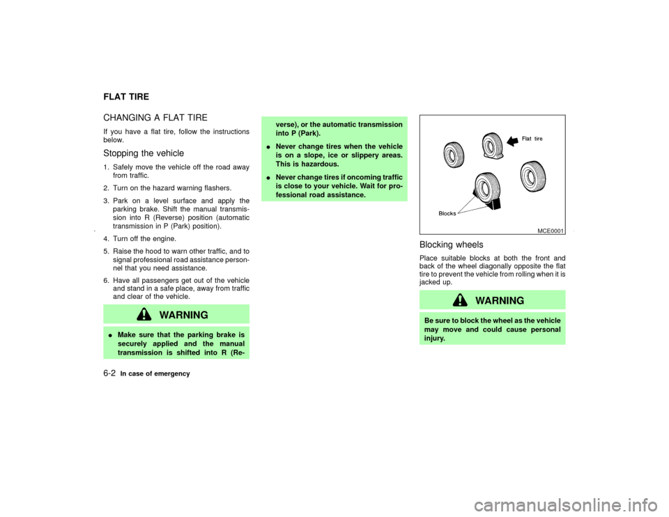
Blocking wheelsPlace suitable blocks at both the front and
back of the wheel diagonally opposite the flat
tire to prevent the vehicle from rolling when it is
jacked up.
WARNING
Be sure to block the wheel as the vehicle
may move and could cause personal
injury.
MCE0001
FLAT TIRE6-2
In case of emergency
Z
01.9.21/A33-D/V5.0
X
Page 162 of 247

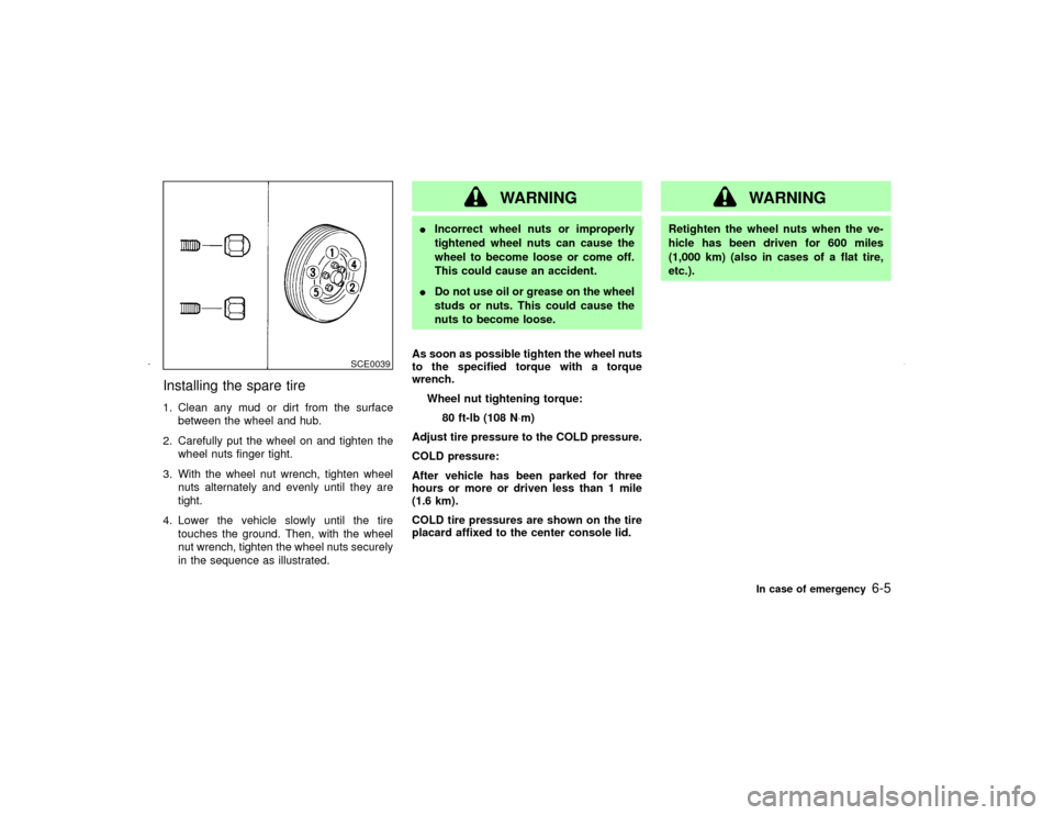
Installing the spare tire1. Clean any mud or dirt from the surface
between the wheel and hub.
2. Carefully put the wheel on and tighten the
wheel nuts finger tight.
3. With the wheel nut wrench, tighten wheel
nuts alternately and evenly until they are
tight.
4. Lower the vehicle slowly until the tire
touches the ground. Then, with the wheel
nut wrench, tighten the wheel nuts securely
in the sequence as illustrated.
WARNING
IIncorrect wheel nuts or improperly
tightened wheel nuts can cause the
wheel to become loose or come off.
This could cause an accident.
IDo not use oil or grease on the wheel
studs or nuts. This could cause the
nuts to become loose.
As soon as possible tighten the wheel nuts
to the specified torque with a torque
wrench.
Wheel nut tightening torque:
80 ft-lb (108 N×m)
Adjust tire pressure to the COLD pressure.
COLD pressure:
After vehicle has been parked for three
hours or more or driven less than 1 mile
(1.6 km).
COLD tire pressures are shown on the tire
placard affixed to the center console lid.
WARNING
Retighten the wheel nuts when the ve-
hicle has been driven for 600 miles
(1,000 km) (also in cases of a flat tire,
etc.).
SCE0039
In case of emergency
6-5
Z
01.9.21/A33-D/V5.0
X