2002 MERCEDES-BENZ SLK 230 KOMPRESSOR Battery
[x] Cancel search: BatteryPage 224 of 290
221 Battery
Te ch n i c a l
data Instruments
and controlsOperation DrivingInstrument
cluster displayPractical hintsCar care Index Therefore, we strongly recommend that you have the
battery charge checked frequently, and corrected if
necessary, especially if you use the vehicle less than
approximately 200 miles (300 km) per month,
mostly for short distance trips, or if it is not used for
long periods of time.
Only charge a battery with a battery charger after the
battery has been disconnected from the vehicle’s
electrical circuit.
Always disconnect the battery negative lead first and
connect last.
When removing and connecting the battery, always
make sure that all electrical consumers are off and the
key is in steering lock position 0. The battery must
always be securely installed when the vehicle is in
operation. During removal and installation always
protect the disconnected battery positive (+) terminal
with the cover attached to the battery.
While the engine is running the battery terminal clamps
must not be loosened or detached, otherwise the
generator and other electronic components will be
damaged.Battery recycling
Batteries contain materials that can harm the
environment with improper disposal.
Large 12 Volt storage batteries contain lead.
Recycling of batteries is the preferred method of
disposal.
Many states require sellers of batteries to accept old
batteries for recycling.
Page 225 of 290
222 Battery
Te ch n i c a l
data Instruments
and controlsOperation DrivingInstrument
cluster displayPractical hintsCar care Index
Jump startingImportant!
A discharged battery can freeze at approximately +14°F
(–10°C). In that case, it must be thawed out before
jumper cables are used. Attempting to jump start a
frozen battery can result in exploding, causing personal
injury.
Jumper cable specifications:
•Minimum cable cross-section of 25 mm
2 or
approximately 2 AWG
•Maximum length of 11.5 ft. (3.5 m).
If the battery is discharged, the engine should be started
with jumper cables and the (12 V) battery of another
vehicle.
Only use 12 V battery to jump start your vehicle. Jump
starting with more powerful battery could damage the
vehicle’s electrical systems, which will not be covered
by the Mercedes-benz Limited Warranty.
The battery is located in the engine compartment.
Wa r n i n g !
Failure to follow these directions will cause
damage to the electronic components, and can lead
to a battery explosion and severe injury or death.Never lean over batteries while connecting or jump
starting, you might get injured.Battery fluid contains sulfuric acid. Do not allow
this fluid to come in contact with eyes, skin or
clothing. In case it does, immediately flush affected
area with water, and seek medical help if
necessary.A battery will also produce hydrogen gas, which is
flammable and very explosive. Keep flames or
sparks away from battery, avoid improper
connection of jumper cables, smoking etc..Read all instructions before proceeding.
Page 226 of 290

223 Jump starting
Te ch n i c a l
data Instruments
and controlsOperation DrivingInstrument
cluster displayPractical hintsCar care Index Proceed as follows:
1. Position the vehicle with the charged battery so that
the jumper cables will reach, but never let the
vehicles touch. Make sure the jumper cables do not
have loose or missing insulation.
2. On both vehicles:
•Turn off engine and all lights and accessories,
except hazard warning flashers or work lights.
•Apply parking brake and shift selector lever to
position “P” (manual transmission to Neutral).
Important!
3. Clamp one end of the first jumper cable to the
positive (+) terminal of the discharged battery and
the other end to the positive (+) terminal of the
charged battery. Make sure the cable clamps do not
touch any other metal parts.
4. Clamp one end of the second jumper cable to the
grounded negative (–) terminal of the charged
battery and the final connection to a grounded
heavy metal bracket in the engine compartment or
on the engine of the disabled vehicle.Important!
5. Start engine of the vehicle with the charged battery
and run at high idle. Make sure the cables are not
on or near pulleys, fans, or other parts that will
move when the engine is started. Allow the
discharged battery to charge for a few minutes. Start
engine of the disabled vehicle in the usual manner.
6. After the engine has started, remove jumper cables
by exactly reversing the above installation
sequence, starting with the last connection made
first. When removing each clamp, make sure that it
does not touch any other metal while the other end
is still attached.
Note:
If engine does not run after several unsuccessful
starting attempts, have it checked at the nearest
authorized Mercedes-Benz Center.
Excessive unburned fuel may damage the catalytic
converter.
Page 239 of 290

236 Remote control
Te ch n i c a l
data Instruments
and controlsOperation DrivingInstrument
cluster displayPractical hintsCar care Index
Changing batteries in the remote control
Checking batteries
If the transmit buttonŒ or‹ is pressed longer
than 1 second, the battery check lamp in the transmitter
eye (1) lights up briefly – indicating that the batteries
are in order.
Change batteries if the battery check lamp does not light
up briefly.Changing batteries
Unfold master key from holder by pressing key release
button (2). Pull off battery cover (3).
Page 240 of 290
237 Remote control
Te ch n i c a l
data Instruments
and controlsOperation DrivingInstrument
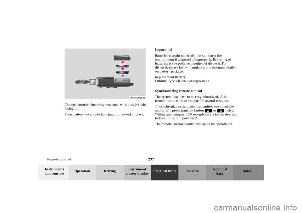
cluster displayPractical hintsCar care Index Change batteries, inserting new ones with plus (+) side
facing up.
Press battery cover onto housing until locked in place.Important!
Batteries contain materials that can harm the
environment if disposed of improperly. Recycling of
batteries is the preferred method of disposal. For
disposal, please follow manufacturer‘s recommendation
on battery package.
Replacement Battery:
Lithium, type CR 2025 or equivalent.
Synchronizing remote control
The system may have to be resynchronized, if the
transmitter is without voltage for several minutes.
To synchronize system, aim transmitter eye at vehicle
and briefly press transmit buttonŒ or‹ twice.
Within approximately 30 seconds insert key in steering
lock and turn it to position 2.
The remote control should once again be operational.
Page 267 of 290

264 Technical data
Te ch n i c a l
data Instruments
and controlsOperation DrivingInstrument
cluster displayPractical hints Car care Index
Electrical system
SLK 230 KOMPRESSOR SLK 320 SLK 32 AMG
Generator (alternator) 14 V / 90 A 14 V / 115 A 14 V / 120 A
Starter motor 12V / 1.1 kW 12V / 1.7 kW 12V / 1.7 kW
Battery 12V/74 Ah 12V/74 Ah 12V/74 Ah
Spark plugs
Electrode gap
Tightening torqueBosch F 7 KTCR
0.039 in (1.0 mm)
15 – 22 ft.lb (20 – 30 Nm)Bosch F 8 DPER
Beru 14 FGH 8 DPUR X 2
NGK PFR 5-11
0.039 in (1.0 mm)
15 – 22 ft.lb (20 – 30 Nm)NGK IFR 6D1O
0.039 in (1.0 mm)
15 – 22 ft.lb (20 – 30 Nm)
Page 277 of 290
274 Index
Te ch n i c a l
data Instruments
and controlsOperation DrivingInstrument
cluster displayPractical hints Car careIndex
Index
AABS (Antilock brake system) ....................................... 171
Malfunction indicator lamp ..................................... 186
Adjusting telescoping steering column ........................ 65
Air conditioner refrigerant ........................................... 268
Air pump (except SLK 32 AMG) ..................................200
Air pump (SLK 32 AMG only) ...................................... 202
Airbag deactivation system ............................................ 51
AIRBAG OFF indicator lamp ........................................ 190
Airbags .............................................................................. 54
Alarm system ............................................................. 35, 37
Antenna ........................................................................... 244
Anticorrosion / antifreeze .................. 164, 198, 266, 270
Antilock brake system (ABS) ....................................... 171
Malfunction indicator lamp ..................................... 186
Antitheft alarm system ................................................... 35
Aquaplaning ................................................................... 161
Ashtrays ...........................................................................116
Audio system .................................................................... 93
Anti-theft system ........................................................ 95
Button and soft key operation ................................... 96
Cassette mode ........................................................... 101CD changer ................................................................. 105
CD mode ..................................................................... 104
Operating and display elements ...............................94
Operating safety ..........................................................93
Operation – audio and telephone ............................. 93
Radio mode .................................................................. 99
Telephone operation ................................................. 108
Automatic central locking .............................................. 31
Automatic transmission ................................................ 147
Emergency Operation ............................................... 155
Fluid level ................................................................... 196
Program mode selector switch ................................ 154
Selector lever positions ............................................ 150
Transmission selector lever,
manually unlocking ............................................ 229
BBabySmart
TM airbag deactivation system ..................... 51
Self-test ......................................................................... 51
BAS (Brake assist system) ............................................ 169
Malfunction indicator lamp ..................................... 185
Battery ............................................................................ 220
Charge indicator lamp .............................................. 188
Recycling ....................................................................221
Page 283 of 290
280 Index
Te ch n i c a l
data Instruments
and controlsOperation DrivingInstrument
cluster displayPractical hints Car careIndex
NNight security illumination ..........................................112OOn-board diagnostic system ......................................... 182
Operator’s manual ............................................................. 6
Outside temperature indicator ...................................... 75
Overhead control panel ................................................... 19PPanic button ...................................................................... 26
Parcel net in passenger footwell ..................................118
Parking ............................................................................ 159
Parking brake ............................... 156, 158, 159, 174, 183
Power assistance ............................................................ 158
Power seats ....................................................................... 38
Power windows ................................................................ 111
Express opening ........................................................ 111
Operate with hard top switch ................................. 122
Problems with your vehicle ........................................... 12
Product information .......................................................... 5
RRadio
See Radio mode ........................................................... 99
Radio and telephone ...................................................... 130
Radio transmitters ......................................................... 130
Rear view mirrors ............................................................ 66
Exterior ......................................................................... 67
Inside ............................................................................66
Rear window defroster .................................................... 90
Remote control ................................................................. 22
Battery replacement ................................................ 236
Synchronizing .......................................................... 237
Replacing bulbs ............................................................. 230
Replacing wiper blade insert ...................................... 243
Reporting safety defects ................................................. 13
Residual Engine Heat Utilization (REST) ..................... 91
Retractable hardtop .......................................................122
Roadside assistance ........................................................... 8
Roadside assistance call
See Tele Aid ............................................................... 132