Page 192 of 290

189 Malfunction and indicator lamps
Te ch n i c a l
data Instruments
and controlsOperation DrivingInstrument
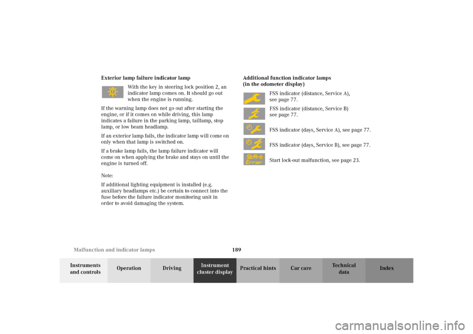
cluster displayPractical hints Car care Index Exterior lamp failure indicator lamp
With the key in steering lock position 2, an
indicator lamp comes on. It should go out
when the engine is running.
If the warning lamp does not go out after starting the
engine, or if it comes on while driving, this lamp
indicates a failure in the parking lamp, taillamp, stop
lamp, or low beam headlamp.
If an exterior lamp fails, the indicator lamp will come on
only when that lamp is switched on.
If a brake lamp fails, the lamp failure indicator will
come on when applying the brake and stays on until the
engine is turned off.
Note:
If additional lighting equipment is installed (e.g.
auxiliary headlamps etc.) be certain to connect into the
fuse before the failure indicator monitoring unit in
order to avoid damaging the system.Additional function indicator lamps
(in the odometer display)
FSS indicator (distance, Service A),
see page 77.
FSS indicator (distance, Service B)
see page 77.
FSS indicator (days, Service A), see page 77.
FSS indicator (days, Service B), see page 77.
Start lock-out malfunction, see page 23.
Page 193 of 290

190 Malfunction and indicator lamps
Te ch n i c a l
data Instruments
and controlsOperation DrivingInstrument
cluster displayPractical hints Car care Index
Malfunction and indicator lamp in the
center console
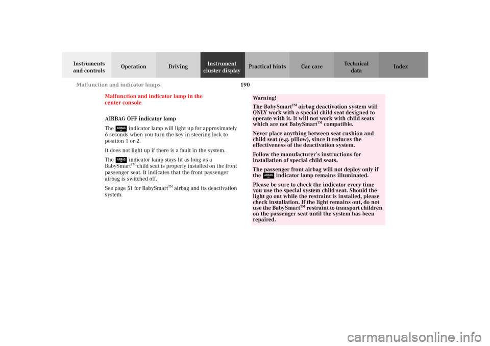
AIRBAG OFF indicator lamp
The 7 indicator lamp will light up for approximately
6 seconds when you turn the key in steering lock to
position 1 or 2.
It does not light up if there is a fault in the system.
The 7 indicator lamp stays lit as long as a
BabySmart
TM child seat is properly installed on the front
passenger seat. It indicates that the front passenger
airbag is switched off.
See page 51 for BabySmart
TM airbag and its deactivation
system.
Wa r n i n g !
The BabySmart
TM airbag deactivation system will
ONLY work with a special child seat designed to
operate with it. It will not work with child seats
which are not BabySmart
TM compatible.
Never place anything between seat cushion and
child seat (e.g. pillow), since it reduces the
effectiveness of the deactivation system.Follow the manufacturer’s instructions for
installation of special child seats.The passenger front airbag will not deploy only if
the 7 indicator lamp remains illuminated.Please be sure to check the indicator every time
you use the special system child seat. Should the
light go out while the restraint is installed, please
check installation. If the light remains out, do not
use the BabySmart
TM restraint to transport children
on the passenger seat until the system has been
repaired.
Page 194 of 290

191 Contents - Practical hints
Te ch n i c a l
data Instruments
and controlsOperation DrivingInstrument
cluster displayPractical hintsCar care Index
Practical hintsFirst aid kit ..................................... 192
Stowing items in the vehicle ........ 192
Fuses ................................................ 192
Hood ................................................. 194
Automatic transmission
fluid level ................................... 196
Checking engine oil level ............. 197
Coolant level ................................... 198
Adding coolant ........................... 198
Windshield and
headlamp washer system ........ 199
Air pump, spare wheel,
vehicle tools,
storage compartment
(except SLK 32 AMG) ...............200Ve h i c l e j a c k
(except SLK 32 AMG) .............. 201
Storage box, TIREFIT-Kit,
air pump, Vehicle tools
(SLK 32 AMG only) .................. 202
Wheels ............................................ 203
Tire replacement ....................... 203
Rotating wheels ......................... 204
Spare wheel .................................... 205
Spare wheel bolts ...................... 206
Changing wheels ........................... 207
Inflating the collapsible
spare tire ......................................212
Storing spare wheel in
wheel well ....................................213
TIREFIT ............................................214
Tire inflation pressure .................. 219Battery .............................................220
Jump starting ..................................222
Towing the vehicle .........................224
Transmission selector lever,
manually unlocking ..................229
Exterior lamps ................................230
Headlamp assembly ................... 231
Taillamp assemblies ..................234
Changing batteries in
the remote control ....................236
Synchronizing
remote control ............................237
Raising hardtop manually ............238
Replacing wiper blade insert .......243
Antenna ...........................................244
Manual release
of fuel filler flap ........................244
Page 196 of 290
193 Fuses
Te ch n i c a l
data Instruments
and controlsOperation DrivingInstrument
cluster displayPractical hintsCar care Index 1Main fuse box in engine compartment (contains
fuses for interior consumers)
To gain access to the main fuse box (1), release
clamp (arrow), lift the fuse box cover up and
remove it.
To close the main fuse box, engage back end of cover
and let front end snap into place.2Auxiliary fuse box to left of exterior lamp switch
(fuses for lights)
To gain access, turn locks (arrows) using a coin, and
remove cover.
1
P82.00-2050-26
P82.00-2064-26
2
Page 198 of 290
195 Engine compartment
Te ch n i c a l
data Instruments
and controlsOperation DrivingInstrument
cluster displayPractical hintsCar care Index To o pen :
To unlock the hood, pull release lever (1) under the
driver’s side of the instrument panel.
Caution!
To avoid damage to the windshield wipers or hood, open
the hood only with wipers in the parked position.Pull handle (2) up and open hood.
Lower hood and let it drop into lock from a height of
approximately 1 ft. (30 cm), assisting with hands placed
flat on edges of hood (3).
To avoid hood damage, please make sure that hood is
fully closed. If not, repeat closing procedure. Do not
push down on hood to attempt to fully close it.
P88.40-2065-26
3
3
2
Page 201 of 290

198 Coolant level
Te ch n i c a l
data Instruments
and controlsOperation DrivingInstrument
cluster displayPractical hintsCar care Index
Coolant level
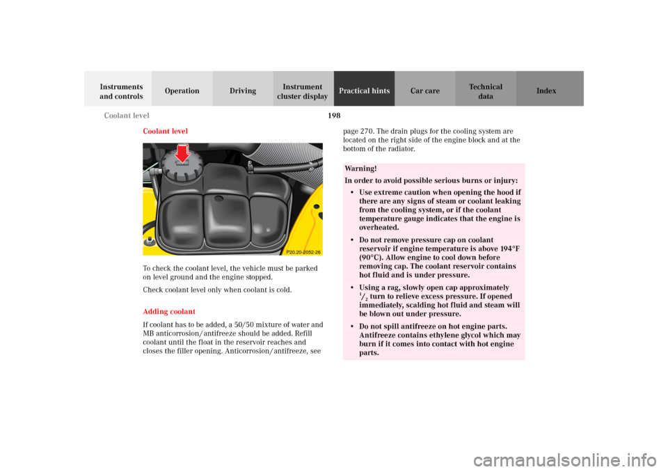
To check the coolant level, the vehicle must be parked
on level ground and the engine stopped.
Check coolant level only when coolant is cold.
Adding coolant
If coolant has to be added, a 50/50 mixture of water and
MB anticorrosion / antifreeze should be added. Refill
coolant until the float in the reservoir reaches and
closes the filler opening. Anticorrosion / antifreeze, see page 270. The drain plugs for the cooling system are
located on the right side of the engine block and at the
bottom of the radiator.
P20.20-2052-26
Wa r n i n g !
In order to avoid possible serious burns or injury:
• Use extreme caution when opening the hood if
there are any signs of steam or coolant leaking
from the cooling system, or if the coolant
temperature gauge indicates that the engine is
overheated.• Do not remove pressure cap on coolant
reservoir if engine temperature is above 194°F
(90°C). Allow engine to cool down before
removing cap. The coolant reservoir contains
hot fluid and is under pressure.• Using a rag, slowly open cap approximately
1/2 turn to relieve excess pressure. If opened
immediately, scalding hot fluid and steam will
be blown out under pressure.
• Do not spill antifreeze on hot engine parts.
Antifreeze contains ethylene glycol which may
burn if it comes into contact with hot engine
parts.
Page 203 of 290
200 Air pump, spare wheel, vehicle tools, storage compartment
Te ch n i c a l
data Instruments
and controlsOperation DrivingInstrument
cluster displayPractical hintsCar care Index
Air pump, spare wheel, vehicle tools, storage
compartment (except SLK 32 AMG)1Vehicle tools
2Wheel bolt wrench
3Spare wheel and wheel bolts
4Air pump (electric. 12 V), Bolts for spare wheel rim
5Ve h i c l e j a c k
Raise roof, open luggage cover, and move aside trunk
floor.
To remove air pump:
Unbuckle strap and remove air pump from holder.
To remove spare wheel:
First remove air pump, then turn pump holder
counterclockwise and remove spare wheel.
To store spare wheel:
Place spare wheel in wheel well and secure it with
pump holder. Turn pump holder clockwise to its stop.
Reinstall air pump.
P58.10-2025-27
43
2
15
Page 204 of 290

201 Vehicle jack
Te ch n i c a l
data Instruments
and controlsOperation DrivingInstrument
cluster displayPractical hintsCar care Index Ve h i c l e j a c k (except SLK 32 AMG)
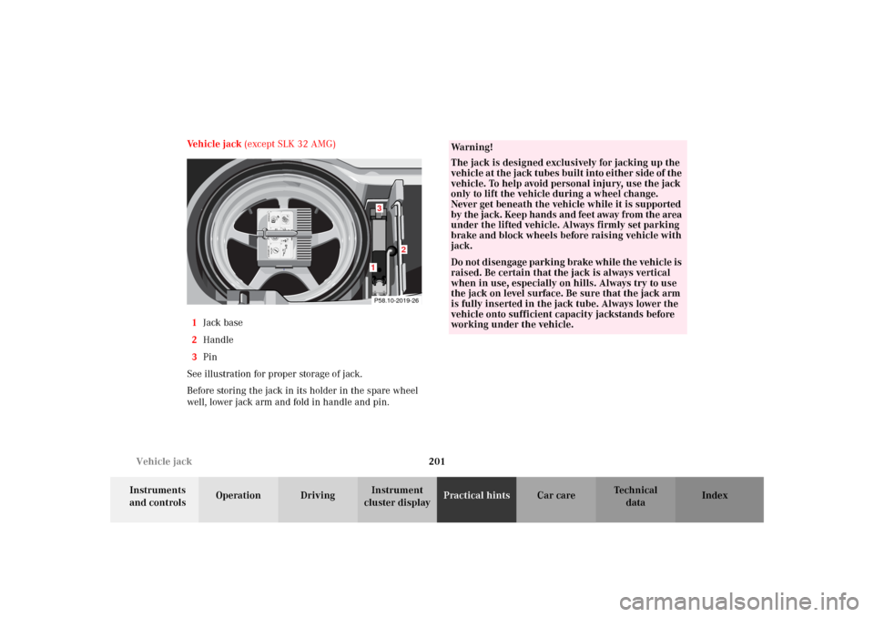
1Jack base
2Handle
3Pin
See illustration for proper storage of jack.
Before storing the jack in its holder in the spare wheel
well, lower jack arm and fold in handle and pin.
1
0
456max. 6 min
A 170 584 01 38 AIR COMPRESSOR 23
Mercedes-Benz2
3
2 1
12,5 bar
36 psi1
0 23
4
5
620PSI
BAR40
60
80LUFTPRESSER 1
2
P58.10-2019-261
2
3
Wa r n i n g !
The jack is designed exclusively for jacking up the
vehicle at the jack tubes built into either side of the
vehicle. To help avoid personal injury, use the jack
only to lift the vehicle during a wheel change.
Never get beneath the vehicle while it is supported
by the jack. Keep hands and feet away from the area
under the lifted vehicle. Always firmly set parking
brake and block wheels before raising vehicle with
jack.Do not disengage parking brake while the vehicle is
raised. Be certain that the jack is always vertical
when in use, especially on hills. Always try to use
the jack on level surface. Be sure that the jack arm
is fully inserted in the jack tube. Always lower the
vehicle onto sufficient capacity jackstands before
working under the vehicle.