2002 MERCEDES-BENZ S55AMG check engine
[x] Cancel search: check enginePage 331 of 430
328 Malfunction and warning messages
Te ch n i c a l
data Instruments
and controlsOperation DrivingInstrument
cluster displayPractical hints Car care Index
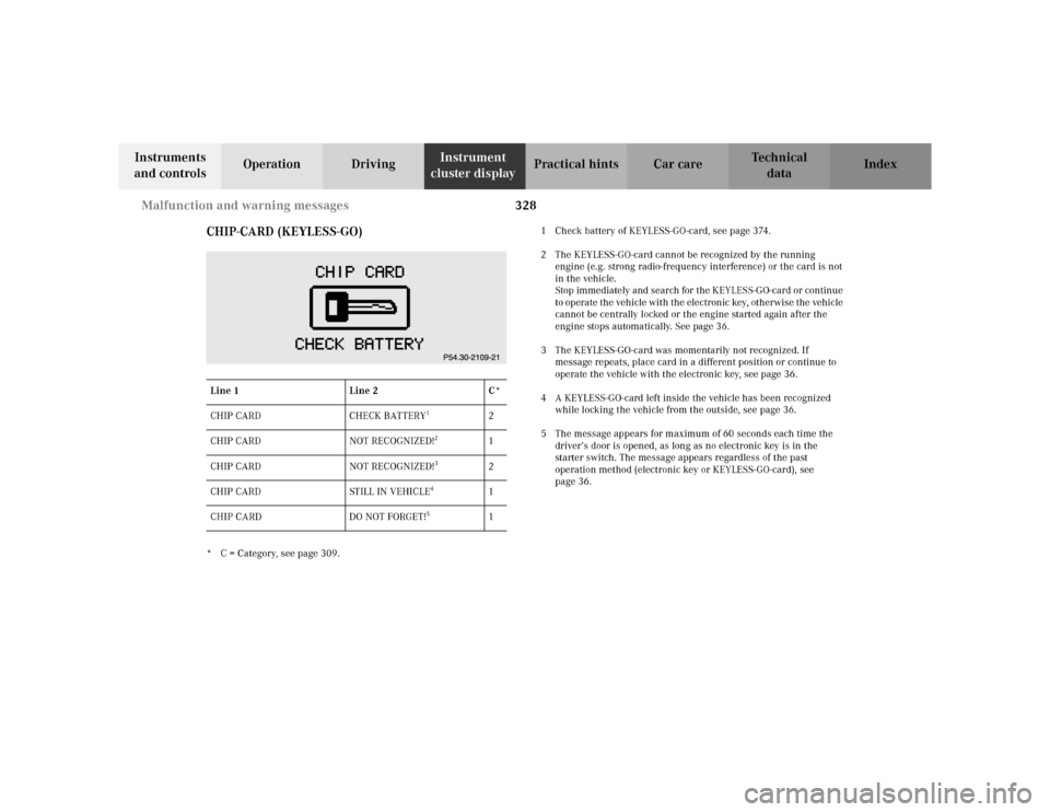
CHIP-CARD (KEYLESS-GO)
* C = Category, see page 309.1 Check battery of KEYLESS-GO-card, see page 374.
2 The KEYLESS-GO-card cannot be recognized by the running
engine (e.g. strong radio-frequency interference) or the card is not
in the vehicle.
Stop immediately and search for the KEYLESS-GO-card or continue
to operate the vehicle with the electronic key, otherwise the vehicle
cannot be centrally locked or the engine started again after the
engine stops automatically. See page 36.
3 The KEYLESS-GO-card was momentarily not recognized. If
message repeats, place card in a different position or continue to
operate the vehicle with the electronic key, see page 36.
4 A KEYLESS-GO-card left inside the vehicle has been recognized
while locking the vehicle from the outside, see page 36.
5 The message appears for maximum of 60 seconds each time the
driver’s door is opened, as long as no electronic key is in the
starter switch. The message appears regardless of the past
operation method (electronic key or KEYLESS-GO-card), see
page 36. Line 1 Line 2 C*
CHIP CARD CHECK BATTERY
1
2
CHIP CARD NOT RECOGNIZED!
2
1
CHIP CARD NOT RECOGNIZED!
3
2
CHIP CARD STILL IN VEHICLE
4
1
CHIP CARD DO NOT FORGET!
5
1
Page 333 of 430
330 Malfunction and warning messages
Te ch n i c a l
data Instruments
and controlsOperation DrivingInstrument
cluster displayPractical hints Car care Index
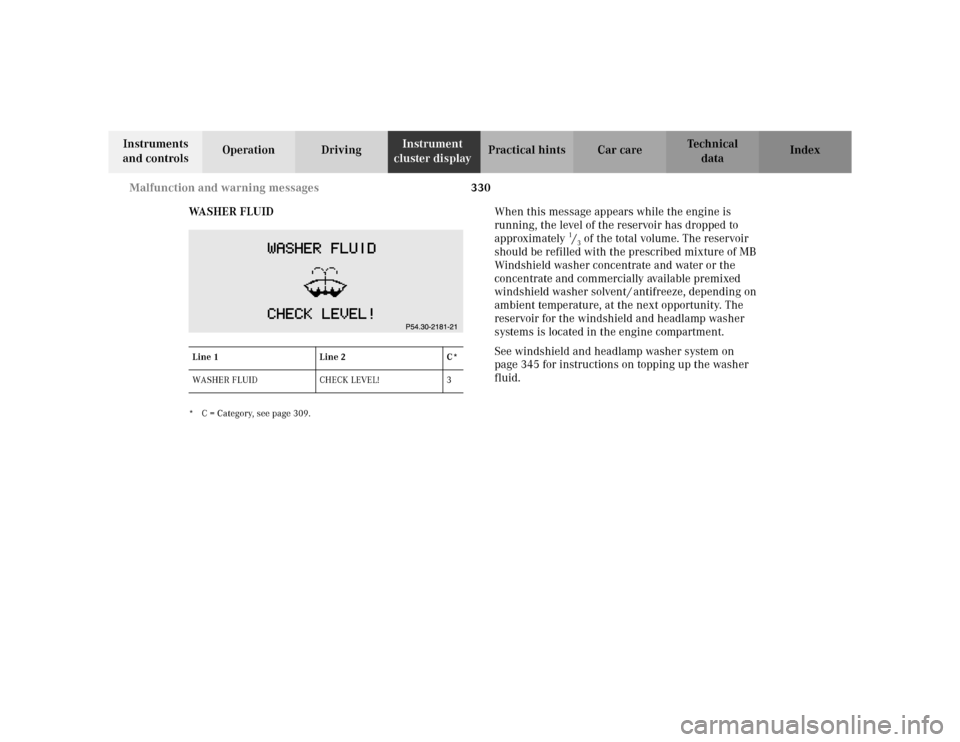
WA S H E R F L U I D
* C = Category, see page 309.
When this message appears while the engine is
running, the level of the reservoir has dropped to
approximately
1/3 of the total volume. The reservoir
should be refilled with the prescribed mixture of MB
Windshield washer concentrate and water or the
concentrate and commercially available premixed
windshield washer solvent / antifreeze, depending on
ambient temperature, at the next opportunity. The
reservoir for the windshield and headlamp washer
systems is located in the engine compartment.
See windshield and headlamp washer system on
page 345 for instructions on topping up the washer
fluid.
Line 1 Line 2 C*
WASHER FLUID CHECK LEVEL! 3
Page 338 of 430
335 Contents – Practical hints
Te ch n i c a l
data Instruments
and controlsOperation DrivingInstrument
cluster displayPractical hintsCar care Index
Practical hintsFirst aid kit .....................................336
Stowing things in the vehicle ......336
Fuses ................................................337
Hood .................................................339
Checking engine oil level .............342
Automatic transmission
fluid level ...................................343
Active body control (ABC)
fluid level ...................................343
Coolant level ...................................344
Adding coolant ...........................344
Windshield and headlamp
washer system ...........................345
Windshield and headlamp
washer fluid mixing ratio .........345Spare wheel, vehicle tools,
storage compartment ............... 346
Vehicle jack .................................... 347
Wheels ............................................ 348
Tire Replacement ....................... 348
Rotating wheels ......................... 349
Spare wheel .................................... 349
Changing wheels ........................... 351
Tire inflation pressure ................. 356
Battery ............................................. 357
Jump starting ................................. 359
Towing the vehicle ........................ 361
Exterior lamps ............................... 364
Headlamp assembly .................. 365
Taillamp assemblies .................. 368Changing batteries in
the electronic key ..................... 371
Synchronizing
remote control ............................373
Changing batteries in the
KEYLESS-GO-card ..................... 374
Emergency engine
shut-down .................................. 376
Fuel filler flap,
manual release .......................... 376
Emergency operation of
sliding/pop-up roof ...................377
Replacing wiper blades .................378
Roof rack .........................................380
Page 345 of 430
342 Engine compartment
Te ch n i c a l
data Instruments
and controlsOperation DrivingInstrument
cluster displayPractical hintsCar care Index
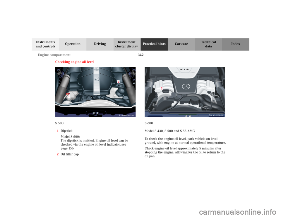
Checking engine oil level
S 500
1Dipstick
Model S 600:
The dipstick is omitted. Engine oil level can be
checked via the engine oil level indicator, see
page 156.
2Oil filler capS 600
Model S 430, S 500 and S 55 AMG
To check the engine oil level, park vehicle on level
ground, with engine at normal operational temperature.
Check engine oil level approximately 5 minutes after
stopping the engine, allowing for the oil to return to the
oil pan.
1
P18.40-0287-262
P18.40-2066-26
2
Page 346 of 430
343 Engine compartment
Te ch n i c a l
data Instruments
and controlsOperation DrivingInstrument
cluster displayPractical hintsCar care Index The engine oil level can be checked by either the oil
dipstick or via the multifunction display in the
instrument cluster, see page 156.
Wipe the oil dipstick clean prior to checking the engine
oil level. Fully insert dipstick in tube, and remove after
three seconds to obtain accurate reading.
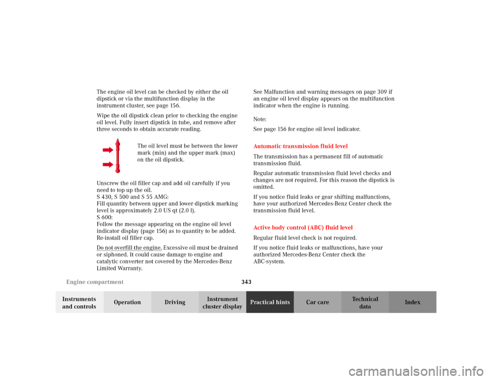
The oil level must be between the lower
mark (min) and the upper mark (max)
on the oil dipstick.
Unscrew the oil filler cap and add oil carefully if you
need to top up the oil.
S 430, S 500 and S 55 AMG:
Fill quantity between upper and lower dipstick marking
level is approximately 2.0 US qt (2.0 l).
S 600:
Follow the message appearing on the engine oil level
indicator display (page 156) as to quantity to be added.
Re-install oil filler cap.
Do not overfill the engine.
Excessive oil must be drained
or siphoned. It could cause damage to engine and
catalytic converter not covered by the Mercedes-Benz
Limited Warranty.See Malfunction and warning messages on page 309 if
an engine oil level display appears on the multifunction
indicator when the engine is running.
Note:
See page 156 for engine oil level indicator.
Automatic transmission fluid level
The transmission has a permanent fill of automatic
transmission fluid.
Regular automatic transmission fluid level checks and
changes are not required. For this reason the dipstick is
omitted.
If you notice fluid leaks or gear shifting malfunctions,
have your authorized Mercedes-Benz Center check the
transmission fluid level.
Active body control (ABC) fluid level
Regular fluid level check is not required.
If you notice fluid leaks or malfunctions, have your
authorized Mercedes-Benz Center check the
ABC-system.
Page 347 of 430
344 Engine compartment
Te ch n i c a l
data Instruments
and controlsOperation DrivingInstrument
cluster displayPractical hintsCar care Index
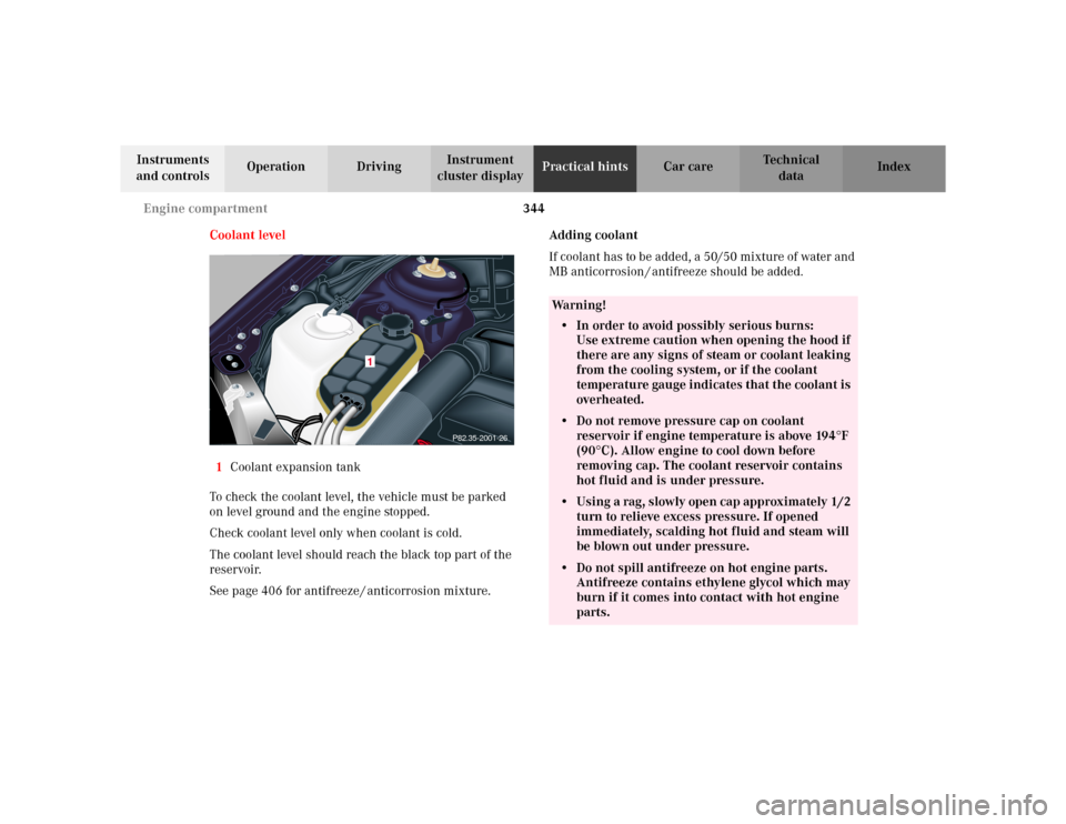
Coolant level
1Coolant expansion tank
To check the coolant level, the vehicle must be parked
on level ground and the engine stopped.
Check coolant level only when coolant is cold.
The coolant level should reach the black top part of the
reservoir.
See page 406 for antifreeze / anticorrosion mixture.Adding coolant
If coolant has to be added, a 50/50 mixture of water and
MB anticorrosion / antifreeze should be added.
P82.35-2001-26
1
Wa r n i n g !
• In order to avoid possibly serious burns:
Use extreme caution when opening the hood if
there are any signs of steam or coolant leaking
from the cooling system, or if the coolant
temperature gauge indicates that the coolant is
overheated.• Do not remove pressure cap on coolant
reservoir if engine temperature is above 194
°F
(90
°C). Allow engine to cool down before
removing cap. The coolant reservoir contains
hot fluid and is under pressure.
• Using a rag, slowly open cap approximately 1/2
turn to relieve excess pressure. If opened
immediately, scalding hot fluid and steam will
be blown out under pressure.• Do not spill antifreeze on hot engine parts.
Antifreeze contains ethylene glycol which may
burn if it comes into contact with hot engine
parts.
Page 361 of 430
358 Battery
Te ch n i c a l
data Instruments
and controlsOperation DrivingInstrument
cluster displayPractical hintsCar care Index
Therefore, we strongly recommend that you have the
battery charge checked frequently, and corrected if
necessary, especially if you use the vehicle less than
approximately 200 miles (300 km) per month,
mostly for short distance trips, or if it is not used for
long periods of time.
Only charge a battery with a battery charger after the
battery has been disconnected from the vehicle’s
electrical circuit.
Always disconnect the battery negative lead first and
connect last.
When removing and connecting the battery, always
make sure that all electrical consumers are off and the
electronic key is in starter switch position 0. The
battery, its filler caps, the vent tube and the opposite
plug must always be securely installed when the vehicle
is in operation.
While the engine is running the battery terminal clamps
must not be loosened or detached, otherwise the
generator and other electronic components would be
damaged.Note:
The gear selector lever will remain locked in
position “P” and the electronic key cannot be turned in
the starter switch, if the vehicle battery disconnected or
discharged.
After reconnecting the battery also set the clock (see
COMAND operator’s manual) resynchronize the front
seat head restraints, the express feature of the power
windows, the sliding / pop-up roof, and the electronic
stability program (see head restraints on page 68, power
windows on page 184, sliding/pop-up roof on page 189,
and electronic stability program on page 280).
Battery recycling
Batteries contain materials that can harm the
environment with improper disposal.
Large 12 Volt storage batteries contain lead.
Recycling of batteries is the preferred method of
disposal.
Many states require sellers of batteries to accept old
batteries for recycling.
Page 363 of 430
360 Jump starting
Te ch n i c a l
data Instruments
and controlsOperation DrivingInstrument
cluster displayPractical hintsCar care Index
Proceed as follows:
1. Position the vehicle with the charged battery so that
the jumper cables will reach, but never let the
vehicles touch. Make sure the jumper cables do not
have loose or missing insulation.
2. On both vehicles:
•Turn off engine and all lights and accessories,
except hazard warning flashers or work lights.
•Apply parking brake and shift selector lever to
position “P”.
Important!
3. Clamp one end of the first jumper cable to the
positive (+) terminal of the discharged battery and
the other end to the positive (+) terminal of the
charged battery. Make sure the cable clamps do not
touch any other metal parts.
4. Clamp one end of the second jumper cable to the
grounded negative (–) terminal of the charged
battery and the final connection to the negative (–)
under hood terminal of the disabled vehicle.Important!
5. Start engine of the vehicle with the charged battery
and run at high idle. Make sure the cables are not
on or near pulleys, fans, or other parts that move
when the engine is started. Allow the discharged
battery to charge for a few minutes. Start engine of
the disabled vehicle in the usual manner.
6. After the engine has started, remove jumper cables
by exactly reversing the above installation
sequence, starting with the last connection made
first. When removing each clamp, make sure that it
does not touch any other metal while the other end
is still attached.
Note:
If engine does not run after several unsuccessful
starting attempts, have it checked at the nearest
authorized Mercedes-Benz Center.
Excessive unburned fuel may damage the catalytic
converter.