2002 MERCEDES-BENZ S500 parking
[x] Cancel search: parkingPage 301 of 430

298 What you should know at the gas station
Te ch n i c a l
data Instruments
and controlsOperationDrivingInstrument
cluster displayPractical hints Car care Index
Tire pressure
For tire pressure, refer to tire pressure label inside the
fuel filler flap. See page 356 for further details.
Air conditioner
R-134a refrigerant and special PAG lubricant, refer to
“Technical Data”.
Spark plugs
Approved spark plugs, refer to “Technical Data”.
Windshield cleaning
To prevent damage to the engine hood, the windshield
wipers must not be folded forward in parked position.
See page 388 for cleaning the windshield.Bulbs
High and low beams: H7 (55 W),
low beam: Xenon (optional)
fog lamps: H1 (55 W),
turn signal lamps,
front 2357 NA (28.5 / 8.3 W [Yellow]),
parking and standing lamps, front: W 5W (5 W)
side marker lamps, front: 5 W / 4 cp,
turn signal lamps, rear: 1156 NA bulb,
tail and parking lamp: P 21 / 4 W,
tail, parking and rear fog lamp, driver’s side: P 21 / 4 W,
tail, parking, standing and
side marker lamp: R 5 W / 4 cp,
backup lamps: 21 W / 32 cp,
license plate lamps: 5 W / 4 cp
Page 304 of 430

301 Contents – Instrument cluster display
Te ch n i c a l
data Instruments
and controlsOperation DrivingInstrument
cluster displayPractical hints Car care Index
Instrument cluster displayMalfunction and indicator
lamps in the
instrument cluster ....................302
On-board diagnostic
system ..........................................302
Check engine malfunction
indicator lamp .............................302
Brake warning lamp ..................304
Supplemental restraint system
(SRS) indicator lamp ..................305
Fuel reserve warning .................305
ABS malfunction
indicator lamp .............................306
Electronic stability program
(ESP) — warning lamp ...............307
Distronic (DTR) –
warning lamp ..............................307
Seat belt nonusage
warning lamp ..............................308Malfunction and indicator
lamp in the
center console ........................... 308
AIRBAG OFF indicator lamp .... 308
Malfunction and warning
messages in the
multifunction display .............. 309
DISPLAY DEFECTIVE ................. 310
BATTERY/ALTERNATOR ........... 311
ENTRANCE POSITION ...............312
BRAKE ASSIST ............................312
BRAKE LINING WEAR ............... 313
BRAKE FLUID ............................. 313
PARKING BRAKE ........................ 314
TRUNK OPEN .............................. 314
ELEC. STABIL. PROG.
(Electronic stability
program) ...................................... 315
COOLANT
(coolant level) .............................. 316
COOLANT
(coolant temperature) ................ 317LIGHTING SYSTEM .................... 318
LIGHT SENSOR ...........................320
ACTIVE BODY CONTROL
(ABC) ............................................320
TIRE PRESSURE .........................322
ENGINE OIL LEVEL ...................324
CRUISE CONTROL .....................325
KEY ...............................................325
DOOR ...........................................326
HOOD ...........................................326
TELE AID .....................................327
CHIP-CARD
(KEYLESS-GO) ............................328
SELECTOR LEVER ......................329
TELEPHONE – FUNCTION .......329
WASHER FLUID .........................330
AIR SPRING (AirMatic) ............. 331
DISTRONIC (DTR) ......................332
AIR CLEANER .............................333
Page 306 of 430
303 Malfunction and indicator lamps
Te ch n i c a l
data Instruments
and controlsOperation DrivingInstrument
cluster displayPractical hints Car care Index may still drive the vehicle, however, in all cases, we
recommend that you have the system checked at your
authorized Mercedes-Benz Center as soon as possible.
If the “CHECK ENGINE” lamp comes on continuously
and / or the vehicle is not driving normally (e.g.
malfunction of the fuel management system or running
out of fuel), serious damage can occur to the emission
system. Please contact your authorized Mercedes-Benz
Center immediately.
The Sequential Multiport Fuel Injection (SFI) control
module monitors emission control components that
either provide input signals to or receive output signals
from the control module. Malfunctions resulting from
interruptions or failure of any of these components are
indicated by the “CHECK ENGINE” malfunction
indicator lamp in the instrument cluster and are
simultaneously stored in the SFI control module.
If the “CHECK ENGINE” malfunction indicator lamp
comes on, have the system checked at your authorized
Mercedes-Benz Center as soon as possible.
With some exceptions, the control module switches off
the “CHECK ENGINE” malfunction indicator lamp if the
condition, causing the lamp to come on, no longer exists
during three consecutive cycles.An on-board diagnostic connector is located in the
passenger compartment near to the parking brake
pedal, allowing the accurate identification of system
malfunctions through the readout of diagnostic trouble
codes.
Notes:
When running out of fuel, the “CHECK ENGINE”
malfunction indicator lamp comes on and the engine
possibly switches to its limp-home (emergency
operation) mode.
To cancel the limp-home mode, the engine may have to
be started three or four times after refueling. The
malfunction indicator lamp remains illuminated. Have
the system checked at your authorized Mercedes-Benz
Center immediately.
Page 307 of 430
304 Malfunction and indicator lamps
Te ch n i c a l
data Instruments
and controlsOperation DrivingInstrument
cluster displayPractical hints Car care Index
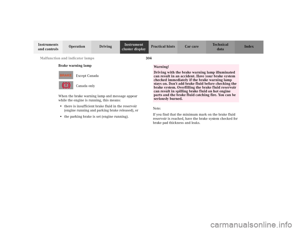
Brake warning lamp
Except Canada
Canada only
When the brake warning lamp and message appear
while the engine is running, this means:
•there is insufficient brake fluid in the reservoir
(engine running and parking brake released), or
•the parking brake is set (engine running).Note:
If you find that the minimum mark on the brake fluid
reservoir is reached, have the brake system checked for
brake pad thickness and leaks.
Wa r n i n g !
Driving with the brake warning lamp illuminated
can result in an accident. Have your brake system
checked immediately if the brake warning lamp
stays on. Don’t add brake fluid before checking the
brake system. Overfilling the brake fluid reservoir
can result in spilling brake fluid on hot engine
parts and the brake fluid catching fire. You can be
seriously burned.
Page 317 of 430

314 Malfunction and warning messages
Te ch n i c a l
data Instruments
and controlsOperation DrivingInstrument
cluster displayPractical hints Car care Index
PA R K I N G B R A K E
* C = Category, see page 309
TRUNK OPEN* C = Category, see page 309 Line 1 Line 2 C*
PARKING BRAKE RELEASE PARKING BRAKE! 1Line 1 Line 2 C*
TRUNK OPEN! 2
Page 350 of 430
347 Vehicle jack
Te ch n i c a l
data Instruments
and controlsOperation DrivingInstrument
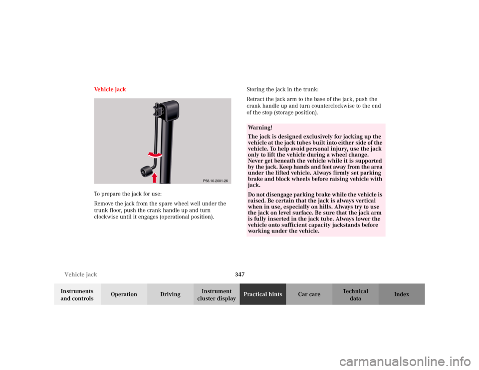
cluster displayPractical hintsCar care Index Ve h i c l e j a c k
To prepare the jack for use:
Remove the jack from the spare wheel well under the
trunk floor, push the crank handle up and turn
clockwise until it engages (operational position).Storing the jack in the trunk:
Retract the jack arm to the base of the jack, push the
crank handle up and turn counterclockwise to the end
of the stop (storage position).
P58.10-2001-26
Wa r n i n g !
The jack is designed exclusively for jacking up the
vehicle at the jack tubes built into either side of the
vehicle. To help avoid personal injury, use the jack
only to lift the vehicle during a wheel change.
Never get beneath the vehicle while it is supported
by the jack. Keep hands and feet away from the area
under the lifted vehicle. Always firmly set parking
brake and block wheels before raising vehicle with
jack.Do not disengage parking brake while the vehicle is
raised. Be certain that the jack is always vertical
when in use, especially on hills. Always try to use
the jack on level surface. Be sure that the jack arm
is fully inserted in the jack tube. Always lower the
vehicle onto sufficient capacity jackstands before
working under the vehicle.
Page 354 of 430
351 Tires, Wheels
Te ch n i c a l
data Instruments
and controlsOperation DrivingInstrument
cluster displayPractical hintsCar care Index Changing wheelsMove vehicle to a level area which is a safe distance
from the roadway.
1. Set parking brake and turn on hazard warning
flasher.
2. Move selector lever to position “P” and turn off
engine.
3. Prevent vehicle from rolling away by blocking
wheels with wheel chocks (not supplied with
vehicle) or sizable wood block or stone. When
changing a wheel on a hill, place chocks on the
downhill side blocking both wheels of the other
axle. On an level road, place one chock in front of
and one behind the wheel that is diagonally
opposite to the wheel being changed.
Wa r n i n g !
The jack is designed exclusively for jacking up the
vehicle at the jack tubes built into either side of the
vehicle. To help avoid personal injury, use the jack
only to lift the vehicle during a wheel change.
Never get beneath the vehicle while it is supported
by the jack. Keep hands and feet away from the area
under the lifted vehicle. Always firmly set parking
brake and block wheels before raising vehicle with
jack.Do not disengage parking brake while the vehicle is
raised. Be certain that the jack is always vertical
when in use, especially on hills. Always try to use
the jack on level surface. Be sure that the jack arm
is fully inserted in the jack tube. Always lower the
vehicle onto sufficient capacity jackstands before
working under the vehicle.
Page 363 of 430
360 Jump starting
Te ch n i c a l
data Instruments
and controlsOperation DrivingInstrument
cluster displayPractical hintsCar care Index
Proceed as follows:
1. Position the vehicle with the charged battery so that
the jumper cables will reach, but never let the
vehicles touch. Make sure the jumper cables do not
have loose or missing insulation.
2. On both vehicles:
•Turn off engine and all lights and accessories,
except hazard warning flashers or work lights.
•Apply parking brake and shift selector lever to
position “P”.
Important!
3. Clamp one end of the first jumper cable to the
positive (+) terminal of the discharged battery and
the other end to the positive (+) terminal of the
charged battery. Make sure the cable clamps do not
touch any other metal parts.
4. Clamp one end of the second jumper cable to the
grounded negative (–) terminal of the charged
battery and the final connection to the negative (–)
under hood terminal of the disabled vehicle.Important!
5. Start engine of the vehicle with the charged battery
and run at high idle. Make sure the cables are not
on or near pulleys, fans, or other parts that move
when the engine is started. Allow the discharged
battery to charge for a few minutes. Start engine of
the disabled vehicle in the usual manner.
6. After the engine has started, remove jumper cables
by exactly reversing the above installation
sequence, starting with the last connection made
first. When removing each clamp, make sure that it
does not touch any other metal while the other end
is still attached.
Note:
If engine does not run after several unsuccessful
starting attempts, have it checked at the nearest
authorized Mercedes-Benz Center.
Excessive unburned fuel may damage the catalytic
converter.