Page 285 of 430
282 Driving systems
Te ch n i c a l
data Instruments
and controlsOperationDrivingInstrument
cluster displayPractical hints Car care Index
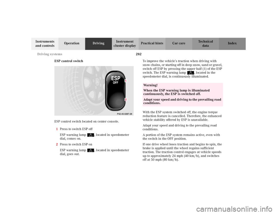
ESP control switch
ESP control switch located on center console.
1Press to switch ESP off
ESP warning lampv, located in speedometer
dial, comes on.
2Press to switch ESP on
ESP warning lampv, located in speedometer
dial, goes out.To improve the vehicle’s traction when driving with
sn ow chain s, or startin g of f in d eep sn ow, san d o r grave l,
switch off ESP by pressing the upper half (1) of the ESP
switch. The ESP warning lampv, located in the
speedometer dial, is continuously illuminated.
With the ESP system switched off, the engine torque
reduction feature is cancelled. Therefore, the enhanced
vehicle stability offered by ESP is unavailable.
Adapt your speed and driving to the prevailing road
conditions.
A portion of the ESP system remains active, even with
the switch in the OFF position.
If one drive wheel loses traction and begins to spin, the
brake is applied until the wheel regains sufficient
traction. The traction control engages at vehicle speeds
up to approximately 24 mph (40 km / h), and switches
off at 50 mph (80 km / h).
Wa r n i n g !
When the ESP warning lamp is illuminated
continuously, the ESP is switched off. Adapt your speed and driving to the prevailing road
conditions.
Page 286 of 430
283 Driving systems
Te ch n i c a l
data Instruments
and controlsOperationDrivingInstrument
cluster displayPractical hints Car care Index Notes:
Avoid spinning of one drive wheel. This may cause
serious damage to the drive train which is not covered
by the Mercedes-Benz Limited Warranty.
The ESP warning lamp, located in the speedometer dial,
starts to flash at any vehicle speed as soon as the tires
lose traction and the wheels begin to spin.
To return to the enhanced vehicle stability offered by
ESP: press lower half (2) of the switch (the ESP warning
lamp in the speedometer dial goes out).
Vehicles with Distronic (DTR):
With the ESP switched off, the Distronic cannot be
switched on. See page 264 for activation of Distronic.Important!
If the ESP warning lamp flashes:
•during take-off, apply as little throttle as possible,
•while driving, ease up on the accelerator.
Wa r n i n g !
ESP should not be switched off during normal
driving other than in circumstances described
above. Disabling of the system will reduce vehicle
stability in standard driving maneuvers.
Page 287 of 430
284 Driving systems
Te ch n i c a l
data Instruments
and controlsOperationDrivingInstrument
cluster displayPractical hints Car care Index
Active body control (ABC)
(optional, standard on model S 600)
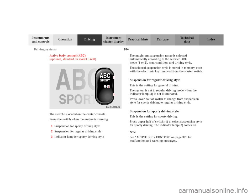
The switch is located on the center console
Press the switch when the engine is running:
1Suspension for sporty driving style
2Suspension for regular driving style
3Indicator lamp for sporty driving styleThe maximum suspension range is selected
automatically according to the selected ABC
mode (1 or 2), road condition, and driving style.
The selected suspension style is stored in memory, even
with the electronic key removed from the starter switch.
Suspension for regular driving style
This is the setting for general driving.
The system is set to regular driving mode when the
indicator lamp (3) is not illuminated.
Press lower half of switch to change from suspension
style for sporty driving to regular driving style.
Suspension for sporty driving style
This is the setting for sporty driving.
Press upper half of switch (1) to select suspension style
for sporty driving. The indicator lamp (3) comes on.
Note:
See “ACTIVE BODY CONTROL” on page 320 for
malfunction and warning messages.
Page 289 of 430
286 Driving systems
Te ch n i c a l
data Instruments
and controlsOperationDrivingInstrument
cluster displayPractical hints Car care Index
The message “AIR SPRING – VEHICLE RISING” appears
in the multifunction display. The display switches off
when the vehicle is raised.
Notes:
The raised level setting switches off at speeds exceeding
approximately 75 mph (120 km / h), or if vehicle speed
is operated between 50 mph (80 km / h) and 75 mph
(120 km / h) for approximately 5 minutes. The message
“AIR SPRING – LEVEL CANCELLED” appears in the
display.
The raised level setting will be stored in memory after
the electronic key is removed from the starter switch if
you did not drive at the aforementioned speeds.
See “AIR SPRING” on page 331 for malfunction and
warning messages.Level control system for vehicles with
Active Body Control (ABC)
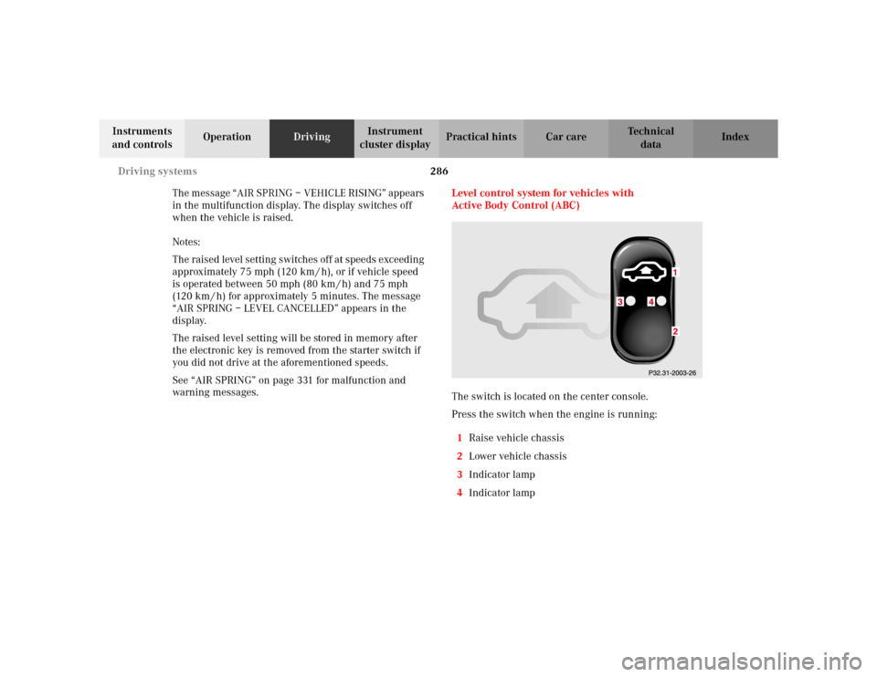
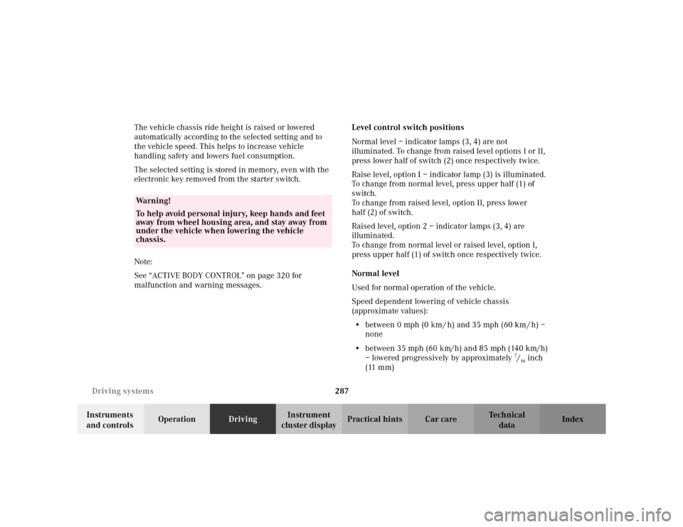
The switch is located on the center console.
Press the switch when the engine is running:
1Raise vehicle chassis
2Lower vehicle chassis
3Indicator lamp
4Indicator lamp
Page 290 of 430
287 Driving systems
Te ch n i c a l
data Instruments
and controlsOperationDrivingInstrument
cluster displayPractical hints Car care Index The vehicle chassis ride height is raised or lowered
automatically according to the selected setting and to
the vehicle speed. This helps to increase vehicle
handling safety and lowers fuel consumption.
The selected setting is stored in memory, even with the
electronic key removed from the starter switch.
Note:
See “ACTIVE BODY CONTROL” on page 320 for
malfunction and warning messages.Level control switch positions
Normal level – indicator lamps (3, 4) are not
illuminated. To change from raised level options I or II,
press lower half of switch (2) once respectively twice.
Raise level, option I – indicator lamp (3) is illuminated.
To change from normal level, press upper half (1) of
switch.
To change from raised level, option II, press lower
half (2) of switch.
Raised level, option 2 – indicator lamps (3, 4) are
illuminated.
To change from normal level or raised level, option I,
press upper half (1) of switch once respectively twice.
Normal level
Used for normal operation of the vehicle.
Speed dependent lowering of vehicle chassis
(approximate values):
•between 0 mph (0 km / h) and 35 mph (60 km / h) –
none
•between 35 mph (60 km/h) and 85 mph (140 km/h)
– lowered progressively by approximately
7/16inch
(11 mm)
Wa r n i n g !
To help avoid personal injury, keep hands and feet
away from wheel housing area, and stay away from
under the vehicle when lowering the vehicle
chassis.
Page 296 of 430
293 Parking system
Te ch n i c a l
data Instruments
and controlsOperationDrivingInstrument
cluster displayPractical hints Car care Index Warning indicators
1Frame
2SegmentsVisual and audible signals indicate to the driver the
relative distance between the vehicle and an obstacle.
Warning indicators for the front area are located above
the left and center air outlets in the dashboard.
Warning indicators for the rear area are integrated in
the rear headliner.
The frames are illuminated when the Parktronic is
engaged.
Each warning indicator has 6 yellow and 2 red
segments.
As soon as the sensors detect an obstacle, one or more
segments light up, depending on the distance. An
intermittent acoustic warning will also sound as the
seventh segment lights up and a constant acoustic
warning lasting a maximum of 3 seconds will sound for
the eighth segment.
2
1
P54.26-0319-26
Page 298 of 430
295 Parking system
Te ch n i c a l
data Instruments
and controlsOperationDrivingInstrument
cluster displayPractical hints Car care Index The obstacle may not be recognized if outside the
shaded sensor field, and no longer be indicated when
approaching it any closer (warning indicators go out).
Parktronic malfunction
All red segments of the warning indicators light up, and
a warning sounds for 3 seconds, if Parktronic does not
function properly.
A dirty sensor or other ultrasonic signals could be the
reason. See page 386 for instructions on cleaning the
sensors in the bumpers.
After cleaning the sensors, turn electronic key in starter
switch to position 2. If the defect continues to be
displayed, have the system checked at your authorized
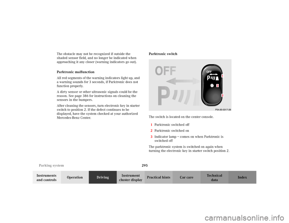
Mercedes-Benz Center.Parktronic switch
The switch is located on the center console.
1Parktronic switched off
2Parktronic switched on
3Indicator lamp – comes on when Parktronic is
switched off
The parktronic system is switched on again when
turning the electronic key in starter switch position 2.3
Page 304 of 430

301 Contents – Instrument cluster display
Te ch n i c a l
data Instruments
and controlsOperation DrivingInstrument
cluster displayPractical hints Car care Index
Instrument cluster displayMalfunction and indicator
lamps in the
instrument cluster ....................302
On-board diagnostic
system ..........................................302
Check engine malfunction
indicator lamp .............................302
Brake warning lamp ..................304
Supplemental restraint system
(SRS) indicator lamp ..................305
Fuel reserve warning .................305
ABS malfunction
indicator lamp .............................306
Electronic stability program
(ESP) — warning lamp ...............307
Distronic (DTR) –
warning lamp ..............................307
Seat belt nonusage
warning lamp ..............................308Malfunction and indicator
lamp in the
center console ........................... 308
AIRBAG OFF indicator lamp .... 308
Malfunction and warning
messages in the
multifunction display .............. 309
DISPLAY DEFECTIVE ................. 310
BATTERY/ALTERNATOR ........... 311
ENTRANCE POSITION ...............312
BRAKE ASSIST ............................312
BRAKE LINING WEAR ............... 313
BRAKE FLUID ............................. 313
PARKING BRAKE ........................ 314
TRUNK OPEN .............................. 314
ELEC. STABIL. PROG.
(Electronic stability
program) ...................................... 315
COOLANT
(coolant level) .............................. 316
COOLANT
(coolant temperature) ................ 317LIGHTING SYSTEM .................... 318
LIGHT SENSOR ...........................320
ACTIVE BODY CONTROL
(ABC) ............................................320
TIRE PRESSURE .........................322
ENGINE OIL LEVEL ...................324
CRUISE CONTROL .....................325
KEY ...............................................325
DOOR ...........................................326
HOOD ...........................................326
TELE AID .....................................327
CHIP-CARD
(KEYLESS-GO) ............................328
SELECTOR LEVER ......................329
TELEPHONE – FUNCTION .......329
WASHER FLUID .........................330
AIR SPRING (AirMatic) ............. 331
DISTRONIC (DTR) ......................332
AIR CLEANER .............................333