Page 305 of 430

302 Malfunction and indicator lamps
Te ch n i c a l
data Instruments
and controlsOperation DrivingInstrument
cluster displayPractical hints Car care Index
Malfunction and indicator lamps
in the instrument cluster
General information:
If a bulb in the instrument cluster fails to light up
during the bulb self-check when turning the electronic
key in steering lock to position 2, have it checked and
replaced if necessary.
Emission control
Certain systems of the engine serve to keep the toxic
components of the exhaust gases within permissible
limits required by law.
These systems, of course, will function properly only
when maintained strictly according to factory
specifications. Any adjustments on the engine should,
therefore, be carried out only by authorized Mercedes-
Benz Center qualified technicians. Engine adjustments
should not be altered in any way. Moreover, the
specified service jobs must be carried out regularly
according to Mercedes-Benz servicing requirements.
For details refer to the Service Booklet.On-board diagnostic system
Check engine malfunction indicator lamp
Engine malfunction indicator lamp. If the
“CHECK ENGINE” malfunction indicator
lamp comes on when the engine is running,
it indicates a malfunction of the fuel management
system, emission control system, systems which impact
emissions, or the fuel cap is not closed tight (check the
fuel cap). If the “CHECK ENGINE” lamp is illuminated
continuously and the vehicle is driving normally, you
Wa r n i n g !
Inhalation of exhaust gas is hazardous to your
health. All exhaust gas contains carbon monoxide,
and inhaling it can cause unconsciousness and
lead to death. Do not run the engine in confined areas (such as a
garage) which are not properly ventilated. If you
think that exhaust gas fumes are entering the
vehicle while driving, have the cause determined
and corrected immediately. If you must drive under
these conditions, drive only with at least one
window fully open.
Page 310 of 430

307 Malfunction and indicator lamps
Te ch n i c a l
data Instruments
and controlsOperation DrivingInstrument
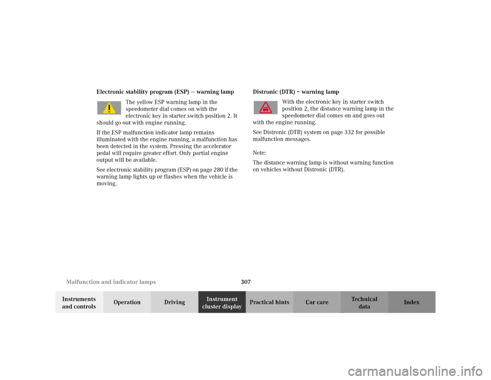
cluster displayPractical hints Car care Index Electronic stability program (ESP) — warning lamp
The yellow ESP warning lamp in the
speedometer dial comes on with the
electronic key in starter switch position 2. It
should go out with engine running.
If the ESP malfunction indicator lamp remains
illuminated with the engine running, a malfunction has
been detected in the system. Pressing the accelerator
pedal will require greater effort. Only partial engine
output will be available.
See electronic stability program (ESP) on page 280 if the
warning lamp lights up or flashes when the vehicle is
moving.Distronic (DTR) – warning lamp
With the electronic key in starter switch
position 2, the distance warning lamp in the
speedometer dial comes on and goes out
with the engine running.
See Distronic (DTR) system on page 332 for possible
malfunction messages.
Note:
The distance warning lamp is without warning function
on vehicles without Distronic (DTR).
Page 311 of 430

308 Malfunction and indicator lamps
Te ch n i c a l
data Instruments
and controlsOperation DrivingInstrument
cluster displayPractical hints Car care Index
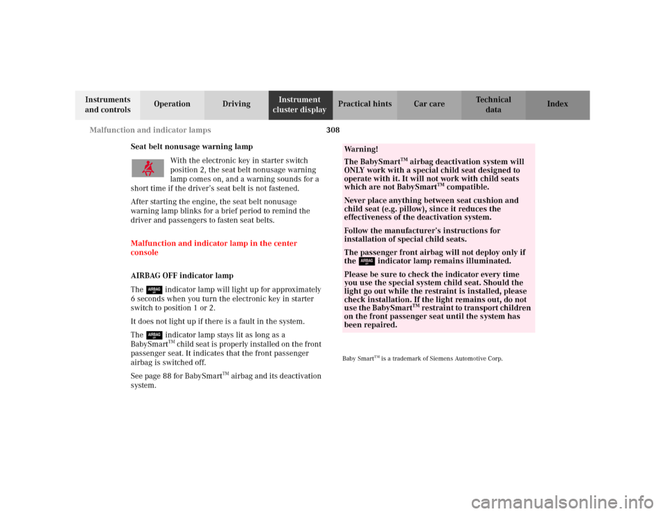
Seat belt nonusage warning lamp
With the electronic key in starter switch
position 2, the seat belt nonusage warning
lamp comes on, and a warning sounds for a
short time if the driver’s seat belt is not fastened.
After starting the engine, the seat belt nonusage
warning lamp blinks for a brief period to remind the
driver and passengers to fasten seat belts.
Malfunction and indicator lamp in the center
console
AIRBAG OFF indicator lamp
The 7 indicator lamp will light up for approximately
6 seconds when you turn the electronic key in starter
switch to position 1 or 2.
It does not light up if there is a fault in the system.
The 7 indicator lamp stays lit as long as a
BabySmart
TM child seat is properly installed on the front
passenger seat. It indicates that the front passenger
airbag is switched off.
See page 88 for BabySmart
TM airbag and its deactivation
system.
Baby Smart
TM is a trademark of Siemens Automotive Corp.
Wa r n i n g !
The BabySmart
TM airbag deactivation system will
ONLY work with a special child seat designed to
operate with it. It will not work with child seats
which are not BabySmart
TM compatible.
Never place anything between seat cushion and
child seat (e.g. pillow), since it reduces the
effectiveness of the deactivation system.Follow the manufacturer’s instructions for
installation of special child seats.The passenger front airbag will not deploy only if
the 7 indicator lamp remains illuminated.Please be sure to check the indicator every time
you use the special system child seat. Should the
light go out while the restraint is installed, please
check installation. If the light remains out, do not
use the BabySmart
TM restraint to transport children
on the front passenger seat until the system has
been repaired.
Page 321 of 430
318 Malfunction and warning messages
Te ch n i c a l
data Instruments
and controlsOperation DrivingInstrument
cluster displayPractical hints Car care Index
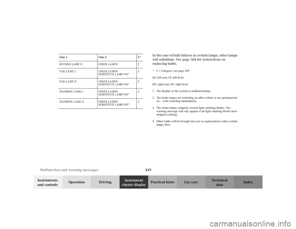
LIGHTING SYSTEM
Line 1 Line 2 C*
LOW BEAM, L CHECK LAMPS! 2
LOW BEAM, R CHECK LAMPS! 2
DISPLAY DEFECTIVE VISIT WORKSHOP!
1
2
TURN SIGNAL LR CHECK LAMPS! 2
TURN SIGNAL RR CHECK LAMPS! 2
TURN SIGNAL IN MIRROR, L CHECK LAMPS! 2
TURN SIGNAL IN MIRROR, R CHECK LAMPS! 2
TURN SIGNAL LF CHECK LAMPS! 2
TURN SIGNAL RF CHECK LAMPS! 2
BRAKE LAMP
2
VISIT WORKSHOP! 2
BRAKE LAMP, L
3
CHECK LAMPS! 2
BRAKE LAMP, R
3
CHECK LAMPS! 2
3RD BRAKE LAMP
3
CHECK LAMPS! 2
HIGH BEAM, L CHECK LAMPS! 2
HIGH BEAM, R CHECK LAMPS! 2
LICENSE PLATE LAMP, L CHECK LAMPS! 2
LICENSE PLATE LAMP, R CHECK LAMPS! 2
TURN OFF LAMPS! 1
FRONT FOGLAMP, L CHECK LAMPS! 2
FRONT FOGLAMP, R CHECK LAMPS! 2
REAR FOGLAMP CHECK LAMPS! 2
REVERSE LAMP, L CHECK LAMPS! 2 Line 1 Line 2 C*
Page 322 of 430

319 Malfunction and warning messages
Te ch n i c a l
data Instruments
and controlsOperation DrivingInstrument
cluster displayPractical hints Car care IndexIn the case of bulb failures in certain lamps, other lamps
will substitute. See page 364 for instructions on
replacing bulbs.
* C = Category, see page 309
LR: left rear; LF: left front
RR: right rear; RF: right front
1 The display or the system is malfunctioning.
2 The brake lamps are switching on after a delay or are permanently
on – visit workshop immediately.
3 The brake lamps comprise several light emitting diodes. The
warning message will only appear if all light emitting diodes have
stopped working.
4 Other bulbs will be brought into use as replacements when certain
lamps blow. REVERSE LAMP, R CHECK LAMPS! 2
TAIL LAMP, L CHECK LAMPS!
SUBSTITUTE LAMP ON!
4
2
TAIL LAMP, R CHECK LAMPS!
SUBSTITUTE LAMP ON!
4
2
STANDING LAMP, L CHECK LAMPS!
SUBSTITUTE LAMP ON!
4
2
STANDING LAMP, R CHECK LAMPS!
SUBSTITUTE LAMP ON!
4
2 Line 1 Line 2 C*
Page 323 of 430
320 Malfunction and warning messages
Te ch n i c a l
data Instruments
and controlsOperation DrivingInstrument
cluster displayPractical hints Car care Index
LAMP SENSOR
* C = Category, see page 309The headlamps will be switched on automatically if the
light sensor malfunctions.
The individual setting menu “LIGHTING” – “LIGHT
CIRCUIT HEADLAMP MODE” can be set to “MANUAL”.
See page 142. It will then be possible to switch the
headlamps on and off using the exterior lamp switch.
See page 158 for notes on the exterior lamp switch. ACTIVE BODY CONTROL (ABC)
* C = Category, see page 309 Line 1 Line 2 C*
LAMP SENSOR VISIT WORKSHOP! 2Line 1 Line 2 C*
DISPLAY DEFECTIVE VISIT WORKSHOP!
1
2
ACTIVE BODY CONTROL DRIVE CAREFULLY!
2
1
ACTIVE BODY CONTROL STOP, CAR TOO LOW!
3
1
ACTIVE BODY CONTROL VISIT WORKSHOP!
4
2
Page 328 of 430
325 Malfunction and warning messages
Te ch n i c a l
data Instruments
and controlsOperation DrivingInstrument
cluster displayPractical hints Car care Index CRUISE CONTROL
* C = Category, see page 309.
1 Cruise control is malfunctioning.
KEY* C = Category, see page 309.
1 Key needs possibly to be replaced. Line 1 Line 2 C*
CRUISE CONTROL VISIT WORKSHOP!
1
2
Line 1 Line 2 C*
REPLACE KEY
1
VISIT WORKSHOP! 2
AUTOM. LIGHT ON REMOVE KEY! 1
P54.30-2245-21
Page 340 of 430

337 Fuses
Te ch n i c a l
data Instruments
and controlsOperation DrivingInstrument
cluster displayPractical hintsCar care Index Fuses
Most of your vehicle’s electrical components are fused
with safety fuses. With the exception of the brake lights,
all individual lighting system components are
electronically fused. Before replacing a blown safety
fuse, determine the cause of the short circuit. Always
observe amperage and color of fuse.
The circuit for components is protected by a cycled
circuit breaker interrupted if too much current is being
drawn. The circuit closes automatically after a short
time; the circuit is broken again if the malfunction
reoccurs.
Always use a new fuse for replacement. Never attempt to
repair or bridge a blown fuse.
A fuse chart, spare fuses and a fuse extractor are located
in the vehicle tool kit in the luggage bowl under the
trunk floor. See page 346 for notes on the vehicle tool
kit.Fuse boxes in the engine compartment
1Fuse box in engine compartment, left-hand side
3Ta b s
3
3
1
P54.15-2007-26