2002 MERCEDES-BENZ ML55AMG wheel torque
[x] Cancel search: wheel torquePage 191 of 342

188 Automatic transmission
Te ch n i c a l
data Instruments
and controlsOperationDrivingInstrument
cluster displayPractical hints Car care Index
Briefly press selector lever in the “D +” direction:
The transmission will shift from the current gear range
to the next higher gear range.
Press and hold selector lever in the “D +” direction:
The transmission will shift from the current gear range
directly to gear range “D”.
Important!
With transmission in gear range “D”, “4” or “3”,
upshifting from 1st to 2nd to 3rd gear is delayed
depending on vehicle speed and engine temperature.
This allows the catalytic converter to heat up more
quickly to operating temperatures.During the brief warm-up period this delayed upshift
and increased engine noise might be perceived as a
malfunction. However, neither the engine nor
transmission are negatively affected by this mode of
operation.
The delayed upshift is effective with vehicle speeds
below 31 mph (50 km / h) at partial throttle and engine
temperatures below 95
°F (35
°C).
To prevent the engine from laboring at low RPM when
driving uphill gradients or with your vehicle heavily
loaded, the automatic transmission will downshift when
necessary to maintain engine RPM within the best
torque range.
Wa r n i n g !
On slippery road surfaces, never downshift in order
to obtain braking action. This could result in drive
wheel slip and reduced vehicle control. Your
vehicle’s ABS will not prevent this type of loss of
control.
Page 207 of 342
204 Driving instructions
Te ch n i c a l
data Instruments
and controlsOperationDrivingInstrument
cluster displayPractical hints Car care Index
Driving on embankments, slopes and other steep
inclines should only be done straight up or downhill, i.e.
in the line of gravity.
Do not drive along the side of a slope (danger of vehicle
rollover). If in doing so, the vehicle begins to show a
tendency to roll, immediately steer into a line of gravity
(straight up or downhill).
To help avoid the vehicle rolling over, never turn it
around on steep inclines. If the vehicle cannot complete
the attempted climb, back it down in reverse gear.
Utilize the engine’s braking power when descending a
slope, observe the engine speed (do not overrev the
engine). Apply the service brake as needed.
Check the brakes after a lengthy downgrade drive.
Notes:
Avoid excessive engine speeds – drive with moderate
engine speeds (max. 3000 RPM).
Select gear range “2” or “1” on the automatic
transmission, see page 183.Traction in steep terrain:
Be easy on the accelerator and watch for continuous
wheel traction when driving in steep terrain.
The 4-ETS+ helps greatly when starting out on a steep
incline when the front wheels have then the tendency to
slip due to the weight shifting away the front axle.
The 4-ETS+ recognizes the situation and limits the
torque for the front wheels by braking them.
Simultaneously the torque for the rear wheels is
increased.
See page 221 for four wheel electronic traction system
(4-ETS+).
Driving across a hilltop:
To prevent the vehicle from speeding up too much after
climbing a hill, decelerate just ahead of a hilltop (do not
select gear range “N”). Use the momentum of the
vehicle to drive across the hilltop. Driving in this
manner prevents the vehicle from jumping across the
hilltop and thus loosing its forward momentum.
Page 226 of 342
223 Driving systems
Te ch n i c a l
data Instruments
and controlsOperationDrivingInstrument
cluster displayPractical hints Car care Index Electronic stability program (ESP)
The ESP enhances directional control and reduces
driving wheel spin of the vehicle under various driving
conditions.
Over-/understeering of the vehicle is counteracted by
applying brakes to the appropriate wheel to create a
countervailing vehicle movement. Engine torque is also
limited. The ESP warning lamp, located in the
speedometer dial, starts to flash when ESP is in
operation.Important!
If the ESP warning lampv flashes:
•During take-off apply as little throttle as possible.
•While driving ease up on the accelerator.
•Adapt your speed and driving to the prevailing road
conditions.
•Do not switch off the ESP.
Caution!
If the vehicle is towed with the front axle raised (see
towing the vehicle on page 277), the engine must be
shut off (key in steering lock position 0 or 1). Otherwise,
the ESP will immediately be engaged and will apply the
rear wheel brakes.
Notes:
The malfunction indicator lamp for the ESP is combined
with that of the BAS.
The yellow BAS / ESP malfunction indicator lamp¿
in the instrument cluster and the yellow ESP warning
lampv in the speedometer dial come on with the
key in steering lock position 2. They should go out with
the engine running.
Wa r n i n g !
ESP cannot prevent the natural laws of physics
from acting on the vehicle, nor can it increase the
traction afforded. The ESP cannot prevent
accidents, including those resulting from excessive
speed in turns, or aquaplaning. Only a safe,
attentive, and skillful driver can prevent accidents.
The capabilities of an ESP equipped vehicle must
never be exploited in a reckless or dangerous
manner which could jeopardize the user’s safety or
the safety of others.
Page 265 of 342
262 Tires, Wheels
Te ch n i c a l
data Instruments
and controlsOperation DrivingInstrument
cluster displayPractical hintsCar care Index
Wheels
Replace rims or tires with the same designation,
manufacturer and type as shown on the original part.
See your authorized Mercedes-Benz Light Truck Center
for further information.
See your authorized Mercedes-Benz Light Truck Center
for information on tested and recommended rims and
tires for summer and winter operation. They can also
offer advice concerning tire service and purchase.Tire replacement
Front and rear tires should be replaced in sets.
Furthermore – in the event of tire replacement – the
optional regular size spare wheel should be used on the
rear axle. Rims and tires must be of the correct size and
type. For dimensions, see technical data on page 310.
We recommend that you break in new tires for
approximately 60 miles (100 km) at moderate speed.
It is imperative that the wheel mounting bolts be
fastened to a tightening torque of 110 ft.lb. (150 Nm)
whenever wheels are mounted.
For rim and tire specifications, refer to technical data on
page 310.
Wa r n i n g !
Do not mix different tire construction types (i.e.
radial, bias, bias-belted) on your vehicle because
handling may be adversely affected and may result
in loss of control.
Wa r n i n g !
Worn, old tires can cause accidents. If the tire tread
is badly worn, or if the tires have sustained
damage, replace them.When replacing rims, use only genuine
Mercedes-Benz wheel bolts specified for the
particular rim type. Failure to do so can result in
the bolts loosening and possibly an accident.
Page 268 of 342
265 Tires, Wheels
Te ch n i c a l
data Instruments
and controlsOperation DrivingInstrument
cluster displayPractical hintsCar care Index Important!
To realize the total crumple zone in case of a rear end
collision, the space-saver spare wheel must be stored in
its holder with the tire deflated. Properly inflate the tire
prior to mounting it on the axle. See page 271 for
detailed instructions.
When storing the space-saver spare wheel in its holder,
tighten the three wheel bolts with a tightening torque of
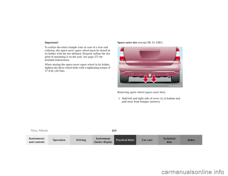
37 ft.lb. (50 Nm).Space-saver tire (except ML 55 AMG)
Removing spare wheel (space-saver tire):
1. Hold left and right side of cover (1) at bottom and
pull away from bumper (arrows).
P40.10-2439-26
Page 273 of 342
270 Tires, Wheels
Te ch n i c a l
data Instruments
and controlsOperation DrivingInstrument
cluster displayPractical hintsCar care Index
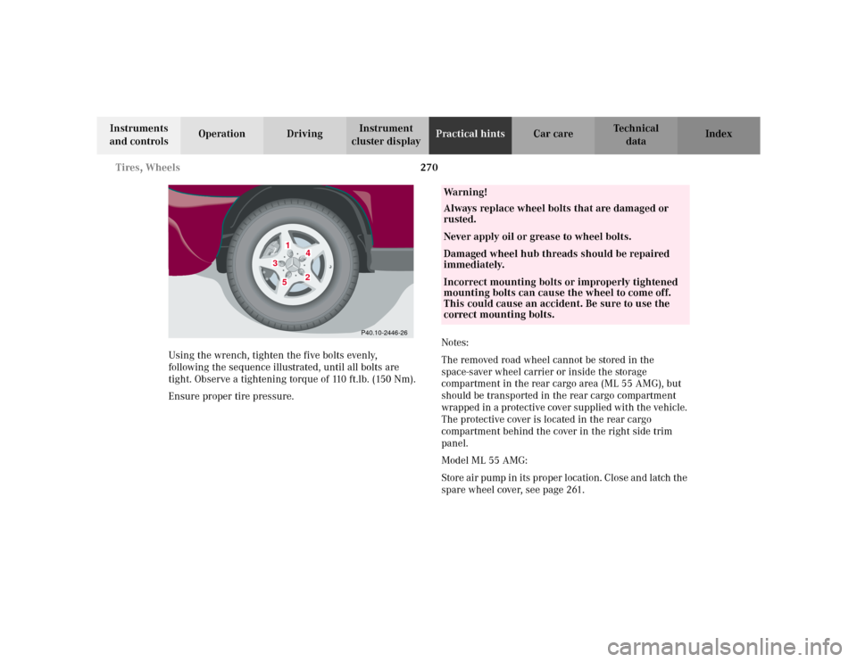
Using the wrench, tighten the five bolts evenly,
following the sequence illustrated, until all bolts are
tight. Observe a tightening torque of 110 ft.lb. (150 Nm).
Ensure proper tire pressure.Notes:
The removed road wheel cannot be stored in the
space-saver wheel carrier or inside the storage
compartment in the rear cargo area (ML 55 AMG), but
should be transported in the rear cargo compartment
wrapped in a protective cover supplied with the vehicle.
The protective cover is located in the rear cargo
compartment behind the cover in the right side trim
panel.
Model ML 55 AMG:
Store air pump in its proper location. Close and latch the
spare wheel cover, see page 261.
1
2
3
4
5
P40.10-2446-26
Wa r n i n g !
Always replace wheel bolts that are damaged or
rusted.Never apply oil or grease to wheel bolts.Damaged wheel hub threads should be repaired
immediately.Incorrect mounting bolts or improperly tightened
mounting bolts can cause the wheel to come off.
This could cause an accident. Be sure to use the
correct mounting bolts.