2002 MERCEDES-BENZ ML55AMG service indicator
[x] Cancel search: service indicatorPage 4 of 342

1 Contents
IntroductionProduct information .......................... 7
Roadside assistance ......................... 10
Where to find it ................................ 14
Reporting Safety Defects ................ 16Instruments and controlsInstruments and controls ............... 18
Center console .............................. 20
Overhead control panel ............... 21OperationVehicle keys ...................................... 24
Start lock-out .................................... 25
General notes on the
central locking system ............... 25
Central locking system ................... 26
Radio frequency
remote control .............................. 26
Unlocking the liftgate .................. 27
Panic button .................................. 28
Mechanical keys ........................... 29Doors ................................................. 30
Central locking switch .................... 32
Automatic central locking .............. 33
Emergency unlocking
in case of accident ...................... 33
Liftgate .............................................. 34
Antitheft alarm system ................... 36
Tow-away alarm and
glass breakage sensor ............... 37
Seats, front ....................................... 38
Manual seats ................................ 40
Power seats .................................... 41
Head restraint .............................. 42
Memory function ......................... 43
Heated seats ..................................... 46
Seat belts and
integrated restraint system ....... 48
Seat belts .......................................... 48
Seat belt nonusage
warning system ............................ 49
BabySmart
TM airbag
deactivation system ................... 55
Self-test BabySmart
TM without
special child seat installed ......... 55Supplemental restraint
system (SRS) ................................ 56
Emergency tensioning
retractor (ETR) ............................. 57
Airbags .............................................. 58
Safety guidelines for
the seat belt, emergency
tensioning retractor
and airbag ..................................... 66
Infant and
child restraint systems ................ 68
Adjustable steering wheel .............. 74
Inside rear view mirror .................. 75
Antiglare night position .............. 75
Exterior rear view mirrors ............. 77
Exterior rear view mirror,
electrically folding ....................... 79
Instrument cluster ........................... 82
Indicator lamps in
the instrument cluster ............... 84
Trip computer ................................... 89
Flexible service system
(FSS) .............................................. 94
Engine oil level indicator ................ 96
Exterior lamp switch ....................... 97
Page 25 of 342

22 Contents - Operation
Te ch n i c a l
data Instruments
and controlsOperationDrivingInstrument
cluster displayPractical hints Car care Index
OperationVehicle keys ...................................... 24
Start lock-out .................................... 25
General notes on the
central locking system ............... 25
Central locking system ................... 26
Radio frequency
remote control .............................. 26
Unlocking the liftgate .................. 27
Panic button .................................. 28
Mechanical keys ........................... 29
Doors .................................................. 30
Central locking switch .................... 32
Automatic central locking .............. 33
Emergency unlocking
in case of accident ...................... 33
Liftgate ............................................... 34
Antitheft alarm system ................... 36
Tow-away alarm and
glass breakage sensor ................ 37
Seats, front ........................................ 38
Manual seats ................................. 40
Power seats ................................... 41Head restraint .............................. 42
Memory function ......................... 43
Heated seats ..................................... 46
Seat belts and
integrated restraint system ....... 48
Seat belts .......................................... 48
Seat belt nonusage
warning system ............................ 49
BabySmart
TM airbag
deactivation system ................... 55
Self-test BabySmart
TM without
special child seat installed ......... 55
Supplemental restraint
system (SRS) ............................... 56
Emergency tensioning
retractor (ETR) ............................ 57
Airbags .............................................. 58
Safety guidelines for
the seat belt, emergency
tensioning retractor
and airbag ..................................... 66
Infant and
child restraint systems ............... 68
Adjustable steering wheel ............... 74
Inside rear view mirror .................. 75Antiglare night position .............. 75
Exterior rear view mirrors ............. 77
Exterior rear view mirror,
electrically folding ....................... 79
Instrument cluster ........................... 82
Indicator lamps in
the instrument cluster ............... 84
Trip computer ................................... 89
Flexible service system
(FSS) .............................................. 94
Engine oil level indicator ................ 96
Exterior lamp switch ....................... 97
Headlamp mode ............................... 99
Night security illumination ......... 101
Locator lighting .......................... 102
Fog lamp switch ............................ 103
Hazard warning flasher
switch .......................................... 104
Headlamp cleaning system .......... 104
Windshield wiper/washer
switch .......................................... 105
Rear window wiper/washer ......... 106
Automatic climate control ............ 108
Dust filter ..................................... 111
Page 88 of 342
85 Instrument cluster
Te ch n i c a l
data Instruments
and controlsOperationDrivingInstrument
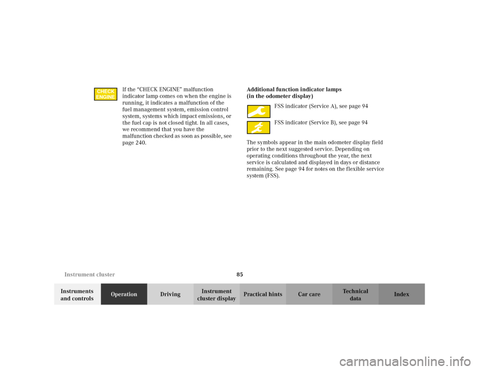
cluster displayPractical hints Car care Index If the “CHECK ENGINE” malfunction
indicator lamp comes on when the engine is
running, it indicates a malfunction of the
fuel management system, emission control
system, systems which impact emissions, or
the fuel cap is not closed tight. In all cases,
we recommend that you have the
malfunction checked as soon as possible, see
page 240.Additional function indicator lamps
(in the odometer display)
FSS indicator (Service A), see page 94
FSS indicator (Service B), see page 94
The symbols appear in the main odometer display field
prior to the next suggested service. Depending on
operating conditions throughout the year, the next
service is calculated and displayed in days or distance
remaining. See page 94 for notes on the flexible service
system (FSS).
CHECK
ENGINE
Page 89 of 342

86 Instrument cluster
Te ch n i c a l
data Instruments
and controlsOperationDrivingInstrument
cluster displayPractical hints Car care Index
Activating instrument cluster display
The display for temperature, odometer, oil level
indicator and clock is activated by:
•Opening the driver’s door.
•Pressing button (1) in the instrument cluster (with
key removed or in steering lock position 0).
•Turning the key in steering lock to position 1 or 2.
The instrument cluster display shuts off automatically.Display illumination
The instrument cluster illumination can be set with the
park lamps, low beam headlamps or high beam
headlamps switched on.
Rotate knob (1) to vary intensity of instrument lamps:
•Clockwise - instrument lamp intensity increases.
•Counterclockwise - instrument lamp intensity
decreases.
Odometer/trip odometer (8)
Activate the instrument cluster.
•Press knob (1) once to switch to or from odometer to
trip odometer readout.
•Press and hold knob (1) for more than 1 second to
reset trip odometer (with trip odometer displayed).
•Press knob (1) twice to display next scheduled
service.
2
Page 97 of 342
94 Flexible service system
Te ch n i c a l
data Instruments
and controlsOperationDrivingInstrument
cluster displayPractical hints Car care Index
Flexible service system (FSS)
(service indicator)
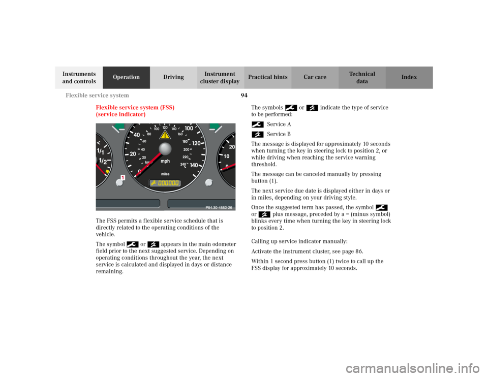
The FSS permits a flexible service schedule that is
directly related to the operating conditions of the
vehicle.
The symbol 9 or ´ appears in the main odometer
field prior to the next suggested service. Depending on
operating conditions throughout the year, the next
service is calculated and displayed in days or distance
remaining.The symbols 9 or ´ indicate the type of service
to be performed:
9Service A
´Service B
The message is displayed for approximately 10 seconds
when turning the key in steering lock to position 2, or
while driving when reaching the service warning
threshold.
The message can be canceled manually by pressing
button (1).
The next service due date is displayed either in days or
in miles, depending on your driving style.
Once the suggested term has passed, the symbol 9
or ´ plus message, preceded by a – (minus symbol)
blinks every time when turning the key in steering lock
to position 2.
Calling up service indicator manually:
Activate the instrument cluster, see page 86.
Within 1 second press button (1) twice to call up the
FSS display for approximately 10 seconds.
Page 98 of 342
95 Flexible service system
Te ch n i c a l
data Instruments
and controlsOperationDrivingInstrument
cluster displayPractical hints Car care Index Important!
The FSS indicator is not an engine oil level indicator.
See page 96 for engine oil level indicator.
Notes:
When disconnecting vehicle battery for one or more
days at a time, such days will not be counted. Any such
days not counted by the FSS can be added by your
Mercedes-Benz Light Truck Center.
The interval between services is determined by the type
of driving for which the vehicle is used. For example,
driving at extreme speeds, and cold starts combined
with short distance driving in which the engine does not
reach normal operating temperature, reduce the interval
between services.
Following a completed A or B service the Mercedes-
Benz Light Truck Center sets the counter mileage to
10 000 miles (Canada: 15 000 km).
The counter can also be set by any individual. To do so:
1. Turn the key in steering lock to position 2.
2. Immediately press button (1) twice within one
second.3. The present status for days or distance is displayed.
Within 10 seconds turn key in steering lock to
position 0.
4. Press and hold button (1), while turning key in
steering lock to position 2 again. The present status
for days or distance is displayed once more.
Continue to hold button (1).
After approximately 10 seconds a signal sounds, and
the display shows 10 000 miles (Canada: 15 000 km)
for approximately 10 seconds.
5. Release button (1).
If the FSS counter was inadvertently reset, have it
corrected at a Mercedes-Benz Light Truck Center.
Note:
However you choose to set your reference numbers, the
scheduled services as posted in the Service Booklet
must be followed to properly care for your vehicle.
Page 169 of 342
166 Tele Aid
Te ch n i c a l
data Instruments
and controlsOperationDrivingInstrument
cluster displayPractical hints Car care Index
Tele Aid (optional for Canada)
Important!
The initial activation of the Tele Aid system may only be
performed by completing the subscriber agreement and
placing an acquaintance call using the “SOS” button.
Failure to complete either of these steps will result in a
system that is not activated. If the system is not
activated the indicator lamp in the “SOS” button stays
on after turning electronic key in starter switch to
position 2 and the message “TELE AID – NOT
ACTIVATED” will be shown in the MCS display for
approx. 10 seconds.
If you have any questions regarding activation, please
call the Response Center at 1-800-756-9018 (in the USA)
or 1-888-923-8367 (in Canada).
(Te l ematic Alarm Identification on Demand)
The Tele Aid system consists of three types of response;
automatic and manual emergency, roadside assistance
and information.The Tele Aid system is operational providing that the
vehicle’s battery is charged, properly connected, not
damaged and cellular and GPS coverage is available.
The speaker volume of a Tele Aid call can be adjusted
using the volume control on the MCS unit. To activate,
press the “SOS” button, the Roadside Assistance
button• or the Information button¡, depending
on the type of response required.
Shortly after the completion of your Acquaintance Call,
you will receive a user ID and password via first call
mail. By visiting www.mbusa.com and selecting
“Tele Aid” (USA only), you will have access to account
information, remote door unlock, Info Services
* profile
and more.
* OptionalSystem self-check
Initially, after turning the key in steering lock to
position 2, malfunctions are detected and indicated (the
indicator lamps in the “SOS” button, the Roadside
Assistance button• and Information button¡
stay on longer than 10 seconds or do not come on). The
message “TELE AID – PLEASE VISIT WORKSHOP”
appears in the MCS display.
Page 171 of 342
168 Tele Aid
Te ch n i c a l
data Instruments
and controlsOperationDrivingInstrument
cluster displayPractical hints Car care Index
The Tele Aid system is available if:
•it has been activated and is operational. Activation
requires a subscription for monitoring services and
cellular air time
•the relevant cellular phone network and GPS signals
are available and pass the information on to the
response center.
Note:
Location of the vehicle on a map is possible if the
vehicle is able to receive signals from the GPS satellite
network and pass the information on to the response
center.
Wa r n i n g !
If the indicator lamp in the “SOS” button is
illuminated continuously and there was no voice
connection to the Response Center established,
then the Tele Aid system could not initiate an
emergency call (e.g. the relevant cellular phone
network is not available). The message
“EMERGENCY CALL – CALL FAILED” appears in
the MCS display for approx. 10 seconds.Should this occur, assistance must be summoned
by other means.