2002 MERCEDES-BENZ ML55AMG brake
[x] Cancel search: brakePage 243 of 342
240 Malfunction and indicator lamps
Te ch n i c a l
data Instruments
and controlsOperation DrivingInstrument
cluster displayPractical hints Car care Index
Malfunction and indicator lamps
in the instrument cluster
General information:
If a bulb in the instrument cluster fails to light up
during the bulb self-check when turning the key in
steering lock to position 2, have it checked and replaced
if necessary.
On-board diagnostic system
Check engine malfunction indicator lamp
Engine malfunction indicator lamp. If the
“CHECK ENGINE” malfunction indicator
lamp comes on when the engine is running,
it indicates a malfunction of the fuel management
system, emission control system, systems which impact
emissions, or the fuel cap is not closed tight (check the
fuel cap). If the “CHECK ENGINE” lamp is illuminated
continuously and the vehicle is driving normally, you
may still drive the vehicle, however, in all cases, we
recommend that you have the system checked at your
authorized Mercedes-Benz Light Truck Center as soon
as possible.
If the “CHECK ENGINE” lamp comes on continuously
and / or the vehicle is not driving normally (e.g.
malfunction of the fuel management system or running out of fuel), serious damage can occur to the emission
system. Please contact your authorized Mercedes-Benz
Light Truck Center immediately.
The Sequential Multiport Fuel Injection (SFI) control
module monitors emission control components that
either provide input signals to or receive output signals
from the control module. Malfunctions resulting from
interruptions or failure of any of these components are
indicated by the “CHECK ENGINE” malfunction
indicator lamp in the instrument cluster and are
simultaneously stored in the SFI control module.
If the “CHECK ENGINE” malfunction indicator lamp
comes on, have the system checked at your authorized
Mercedes-Benz Light Truck Center as soon as possible.
With some exceptions, the control module switches off
the “CHECK ENGINE” malfunction indicator lamp if the
condition, causing the lamp to come on, no longer exists
during three consecutive cycles. See also page 242 for
fuel cap placement warning.
An on-board diagnostic connector is located in the
passenger compartment near to the parking brake
pedal, allowing the accurate identification of system
malfunctions through the readout of diagnostic trouble
codes.
CHECK
ENGINE
Page 244 of 342
241 Malfunction and indicator lamps
Te ch n i c a l
data Instruments
and controlsOperation DrivingInstrument
cluster displayPractical hints Car care Index Notes:
When running out of fuel, the “CHECK ENGINE”
malfunction indicator lamp comes on and the engine
possibly switches to its limp-home (emergency
operation) mode.
To cancel the limp-home mode, the engine may have to
be started three or four times after refueling. The
malfunction indicator lamp remains illuminated. Have
the system checked at your authorized Mercedes-Benz
Center immediately.
Brake warning lamp
The warning lamp in the instrument cluster
comes on with the key in steering lock
position 2 and should go out with the engine
running.
When the brake warning lamp appears while the engine
is running, this means:
•there is insufficient brake fluid in the reservoir
(engine running and parking brake released), or
•the parking brake is set (engine running)
•the electronic brake proportioning (EBP) system is
malfunctioning.Note:
If you find that the minimum mark on the brake fluid
reservoir is reached, have the brake system checked for
brake pad thickness and leaks.
BRAKE
Wa r n i n g !
Driving with the brake warning lamp illuminated
can result in an accident. Have your brake system
checked immediately if the brake warning lamp
stays on. Don’t add brake fluid before checking the
brake system. Overfilling the brake fluid reservoir
can result in spilling brake fluid on hot engine
parts and the brake fluid catching fire. You can be
seriously burned.
Page 247 of 342
244 Malfunction and indicator lamps
Te ch n i c a l
data Instruments
and controlsOperation DrivingInstrument
cluster displayPractical hints Car care Index
ABS malfunction indicator lamp
The ABS malfunction indicator lamp in the
instrument cluster comes on with the key in
steering lock position 2 and should go out
with the engine running.
When the ABS malfunction indicator lamp in the
instrument cluster remains illuminated while the
engine is running, it indicates that the ABS has detected
a malfunction and has switched off. In this case, the
brake system functions in the usual manner, but
without antilock assistance.
With the ABS malfunctioning, the BAS, ESP and 4-ETS+
are also switched off. Both malfunction indicator lamps
come on with the engine running.
If the charging voltage falls below 10 volts, the
malfunction indicator lamp comes on and the ABS is
switched off. When the voltage is above this value again,
the malfunction indicator lamp should go out and the
ABS is operational.
Have the system checked at your authorized
Mercedes-Benz Light Truck Center as soon as possible.
See page 219 for notes on antilock brake system (ABS).Adjustable steering wheel – indicator lamp
The indicator lamp in the instrument cluster
comes on with the key in steering lock
position 2 and should go out with the engine
running.
If the indicator lamp does not go out after starting the
engine, the adjustable steering column is not properly
locked.
For locking the adjustable telescoping steering column,
see page 74.
AIRBAG OFF indicator lamp
The indicator lamp will light up for
approximately 6 seconds, extinguish, then
blink once, when you turn the key in
steering lock to position 1 or 2.
The 7 indicator lamp stays lit as long as a
BabySmart
TM compatible child seat is properly installed
on the front passenger seat. It indicates that the front
passenger airbag is switched off.
See page 55 for BabySmart
TM airbag and its deactivation
system.
BabySmart
TM is a trademark of Siemens Automotive Corp.
ABS
Page 250 of 342
247 Malfunction and indicator lamps
Te ch n i c a l
data Instruments
and controlsOperation DrivingInstrument
cluster displayPractical hints Car care Index Low windshield and headlamp washer system fluid
level warning lamp
With the key in steering lock position 2, the
warning lamp comes on. It should go out
when the engine is running.
If the warning lamp does not go out after starting the
engine, or if it comes on while driving, there is approx.
1.3 US qt (1,25 l) washer fluid remaining the reservoir.
The reservoir should be refilled with MB Windshield
Washer Concentrate “S” and water (or commercially
available premixed windshield washer solvent /
antifreeze, depending on ambient temperature, see
page 258) at the next opportunity. The reservoir for the
windshield and headlamp washer systems is located in
the engine compartment.
Note:
If the warning lamp comes on during subzero wether,
please check the concentration of the washer fluid in
the tank. If the concentration is not sufficient, the fluid
may have frozen. After the fluid in the tank thaws,
correct the concentration level. Brake pad wear indicator lamp
With the key in steering lock position 2, the
indicator lamp comes on and goes out when
the engine is running.
If the indicator lamp lights up during braking, this
indicates that the brake pads are worn down.
Have the brake system checked at your authorized
Mercedes-Benz Light Truck Center as soon as possible.
FSS indicator
FSS indicator (Service A), see page 94.
FSS indicator (Service B), see page 94.
The symbols appear in the main odometer display field
prior to the next suggested service. Depending on
operating conditions throughout the year, the next
service is calculated and displayed in days or distance
remaining. See page 94 for notes on the flexible service
system (FSS).
Page 262 of 342
259 Windshield wiper
Te ch n i c a l
data Instruments
and controlsOperation DrivingInstrument
cluster displayPractical hintsCar care Index Windshield and headlamp washer
fluid mixing ratio
For temperatures above freezing:
MB Windshield Washer Concentrate “S” and water
1 part “S” to 100 parts water
(40 ml “S” to 1 gallon water).
For temperature below freezing:
MB Windshield Washer Concentrate “S” and
commercially available premixed windshield washer
solvent / antifreeze
1 part “S” to 100 parts solvent
(40 ml “S” to 1 gallon solvent).Vehicle jack, wheel bolt wrench and screwdriver
Wa r n i n g !
The jack is designed exclusively for jacking up the
vehicle at the jack take-up brackets built into either
side of the vehicle. To help avoid personal injury,
use the jack only to lift the vehicle during a wheel
change. Never get beneath the vehicle while it is
supported by the jack. Keep hands and feet away
from the area under the lifted vehicle. Always
firmly set parking brake and block wheels before
raising vehicle with jack.Do not disengage parking brake while the vehicle is
raised. Be certain that the jack is always vertical
when in use, especially on hills. Always try to use
the jack on level surface. Be sure that the jack arm
end is fully seated in the jack take-up bracket.
Always lower the vehicle onto sufficient capacity
jackstands before working under the vehicle.
Page 270 of 342
267 Tires, Wheels
Te ch n i c a l
data Instruments
and controlsOperation DrivingInstrument
cluster displayPractical hintsCar care Index Changing wheels
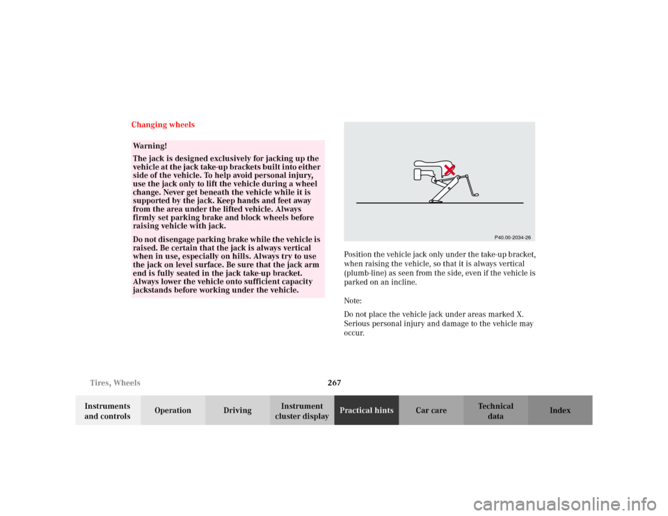
Position the vehicle jack only under the take-up bracket,
when raising the vehicle, so that it is always vertical
(plumb-line) as seen from the side, even if the vehicle is
parked on an incline.
Note:
Do not place the vehicle jack under areas marked X.
Serious personal injury and damage to the vehicle may
occur.
Wa r n i n g !
The jack is designed exclusively for jacking up the
vehicle at the jack take-up brackets built into either
side of the vehicle. To help avoid personal injury,
use the jack only to lift the vehicle during a wheel
change. Never get beneath the vehicle while it is
supported by the jack. Keep hands and feet away
from the area under the lifted vehicle. Always
firmly set parking brake and block wheels before
raising vehicle with jack.Do not disengage parking brake while the vehicle is
raised. Be certain that the jack is always vertical
when in use, especially on hills. Always try to use
the jack on level surface. Be sure that the jack arm
end is fully seated in the jack take-up bracket.
Always lower the vehicle onto sufficient capacity
jackstands before working under the vehicle.
P40.00-2034-26
Page 271 of 342
268 Tires, Wheels
Te ch n i c a l
data Instruments
and controlsOperation DrivingInstrument
cluster displayPractical hintsCar care Index
Move vehicle to a level area which is a safe distance
from the roadway.
Important!
The vehicle doors lock if the left front wheel rotates with
the engine running. Do not leave the engine running
while changing a wheel.
1. Set parking brake and turn on hazard warning
flasher.
2. Move selector lever to position “P”, turn off the
engine, and remove key from the steering lock. Lock
steering wheel with wheels in the straight ahead
position.
3. Prevent vehicle from rolling away by blocking
wheels with wheel chocks (not supplied with
vehicle) or sizable wood block or stone. When
changing a wheel on a hill, place chocks on the
downhill side blocking both wheels of the other
axle. On a level road, place one chock in front of and
one behind the wheel that is diagonally opposite to
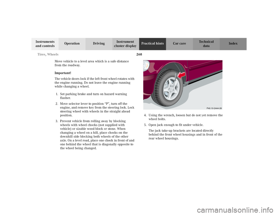
the wheel being changed.4. Using the wrench, loosen but do not yet remove the
wheel bolts.
5. Open jack enough to fit under vehicle.
The jack take-up brackets are located directly
behind the front wheel housings and in front of the
rear wheel housings.
P40.10-2444-26
Page 274 of 342
271 Tires, Wheels
Te ch n i c a l
data Instruments
and controlsOperation DrivingInstrument
cluster displayPractical hintsCar care Index Inflating the space-saver tire (ML 55 AMG only)
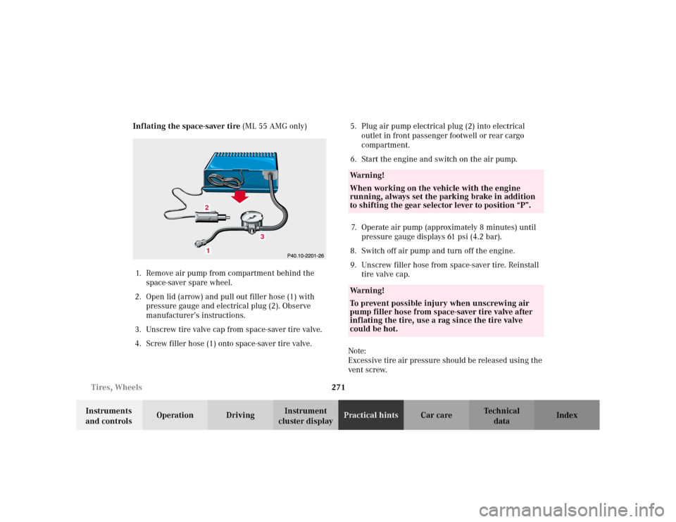
1. Remove air pump from compartment behind the
space-saver spare wheel.
2. Open lid (arrow) and pull out filler hose (1) with
pressure gauge and electrical plug (2). Observe
manufacturer’s instructions.
3. Unscrew tire valve cap from space-saver tire valve.
4. Screw filler hose (1) onto space-saver tire valve.5. Plug air pump electrical plug (2) into electrical
outlet in front passenger footwell or rear cargo
compartment.
6. Start the engine and switch on the air pump.
7. Operate air pump (approximately 8 minutes) until
pressure gauge displays 61 psi (4.2 bar).
8. Switch off air pump and turn off the engine.
9. Unscrew filler hose from space-saver tire. Reinstall
tire valve cap.
Note:
Excessive tire air pressure should be released using the
vent screw.
3
12
Wa r n i n g !
When working on the vehicle with the engine
running, always set the parking brake in addition
to shifting the gear selector lever to position “P”.Wa r n i n g !
To prevent possible injury when unscrewing air
pump filler hose from space-saver tire valve after
inflating the tire, use a rag since the tire valve
could be hot.