2002 MERCEDES-BENZ ML430 jump start
[x] Cancel search: jump startPage 8 of 342

5 Contents
Practical hintsFirst aid kit .....................................250
Fuses ................................................250
Electrical outlet ..............................252
Stowing items in the vehicle ........252
Hood .................................................253
Checking engine oil level .............255
Automatic transmission
fluid level ...................................256
Engine oil consumption ................256
Coolant level ...................................256
Adding coolant ...........................257
Windshield washer/headlamp
cleaning system .........................258
Windshield and headlamp
washer fluid mixing ratio .........259Ve h i c l e j a c k ,
wheel bolt wrench and
screwdriver ............................... 259
Air pump ......................................... 261
Wheels ............................................ 262
Tire replacement ....................... 262
Rotating wheels ......................... 263
Spare wheel .................................... 264
Changing wheels ........................... 267
Tire inflation pressure ................. 272
Battery ............................................. 273
Jump starting ................................. 275
Towing the vehicle ........................ 277
Transmission selector lever,
manually unlocking .................. 281
Stranded vehicle ............................ 281Exterior lamps ................................282
Headlamp assembly ...................283
Taillamp assemblies ..................287
Adjusting headlamp aim ...............290
Remote control battery
replacement ...............................292
Synchronizing
remote control ............................293
Emergency operation of
sliding/pop-up roof ...................294
Manual release for
fuel filler flap .............................295
Replacing wiper blades .................295
Roof rack .........................................296
Page 174 of 342
171 Tele Aid
Te ch n i c a l
data Instruments
and controlsOperationDrivingInstrument
cluster displayPractical hints Car care Index When the connection is established, the message
“ROADSIDE ASSISTANCE – CALL CONNECTED”
appears in the MCS display. The Tele Aid system will
transmit data generating the vehicle identification
number, model, color and location (subject to
availability of cellular and GPS signals).
While the call is connected, you can change to
navigation menu by pressing NAVI button on the MCS.
A voice connection between the Roadside Assistance
dispatcher and the occupants of the vehicle will be
established. When a voice connection is established the
audio system mutes and the message “TELE AID –
ROADSIDE ASSISTANCE CALL ACTIVE” appears in the
MCS display. The nature of the need for assistance can
then be described. The Mercedes-Benz Roadside
assistance dispatcher will either dispatch a qualified
Mercedes-Benz technician or arrange to tow your
vehicle to the nearest Mercedes-Benz Center. For
services such as labor and/or towing charges may apply.
Refer to the Roadside Assistance manual for more
information.These programs are only available in the USA:
•Sign and Drive services: Services such as jump start,
a few gallons of fuel or the replacement of a flat tire
with the vehicle spare tire are obtainable,
•Remote Vehicle Diagnostics: This function permits
the Mercedes-Benz Roadside Assistance dispatcher
to download malfunction codes and actual vehicle
data.
Notes:
The indicator lamp in the Roadside Assistance
button• remains illuminated in red for
approximately 10 seconds during the system self-check
after turning key in steering lock to position 2 (together
with the “SOS” button and the Information
button¡).
See system self-check on page 166 when the indicator
lamp does not light up in red or stay on longer than
approximately 10 seconds.
Page 205 of 342

202 Driving instructions
Te ch n i c a l
data Instruments
and controlsOperationDrivingInstrument
cluster displayPractical hints Car care Index
Off-Road driving
Familiarize yourself with the vehicle characteristics and
gear changing before you attempt any difficult terrain
off-road driving. We recommend that you start out with
easy off-road travel.
Please read this chapter carefully before you begin
off-road travel.
Special driving features are available for specific kinds
of operation:
•LOW RANGE mode, see page 227
•LOW RANGE - ABS, see page 220
•LOW RANGE - 4-ETS+, see page 222
•LOW RANGE - ESP, see page 226
Engage the LOW RANGE mode before driving under
off-road conditions. For switching LOW RANGE mode on
and off see page 227.
Fasten items being carried as securely as possible, see
page 154.
We recommend to keep doors, liftgate, windows, and
roof closed whenever driving in off-road mode.Important!
Adjust vehicle speed to condition of terrain. The more
uneven, rutty and steeper the terrain, the lower the
speed should be.
Watch out for obstacles, such as rocks, holes,
tree-stumps, ruts.
Be especially careful when driving in unknown
territory. Eventually get out of the vehicle and scout the
path you intend to take.
Continuous and speedy driving in sandy soil overcomes
the vehicle rolling resistance, and helps to prevent the
vehicle from sinking into the ground.
Do not initiate jumps with the vehicle. It interrupts the
forward momentum of the vehicle.
Sand, dirt, mud and other material having friction
property, can cause exceptional wear and tear as well as
failure of the brakes.
In this case the brakes may be less effective or even fail
when you most need them. Always clean and check the
brakes following each off-road trip.
Page 207 of 342
204 Driving instructions
Te ch n i c a l
data Instruments
and controlsOperationDrivingInstrument
cluster displayPractical hints Car care Index
Driving on embankments, slopes and other steep
inclines should only be done straight up or downhill, i.e.
in the line of gravity.
Do not drive along the side of a slope (danger of vehicle
rollover). If in doing so, the vehicle begins to show a
tendency to roll, immediately steer into a line of gravity
(straight up or downhill).
To help avoid the vehicle rolling over, never turn it
around on steep inclines. If the vehicle cannot complete
the attempted climb, back it down in reverse gear.
Utilize the engine’s braking power when descending a
slope, observe the engine speed (do not overrev the
engine). Apply the service brake as needed.
Check the brakes after a lengthy downgrade drive.
Notes:
Avoid excessive engine speeds – drive with moderate
engine speeds (max. 3000 RPM).
Select gear range “2” or “1” on the automatic
transmission, see page 183.Traction in steep terrain:
Be easy on the accelerator and watch for continuous
wheel traction when driving in steep terrain.
The 4-ETS+ helps greatly when starting out on a steep
incline when the front wheels have then the tendency to
slip due to the weight shifting away the front axle.
The 4-ETS+ recognizes the situation and limits the
torque for the front wheels by braking them.
Simultaneously the torque for the rear wheels is
increased.
See page 221 for four wheel electronic traction system
(4-ETS+).
Driving across a hilltop:
To prevent the vehicle from speeding up too much after
climbing a hill, decelerate just ahead of a hilltop (do not
select gear range “N”). Use the momentum of the
vehicle to drive across the hilltop. Driving in this
manner prevents the vehicle from jumping across the
hilltop and thus loosing its forward momentum.
Page 252 of 342
249 Contents - Practical hints
Te ch n i c a l
data Instruments
and controlsOperation DrivingInstrument
cluster displayPractical hintsCar care Index
Practical hintsFirst aid kit .....................................250
Fuses ................................................250
Electrical outlet ..............................252
Stowing items in the vehicle ........252
Hood .................................................253
Checking engine oil level .............255
Automatic transmission
fluid level ...................................256
Engine oil consumption ................256
Coolant level ...................................256
Adding coolant ...........................257
Windshield washer/headlamp
cleaning system .........................258
Windshield and headlamp
washer fluid mixing ratio .........259Ve h i c l e j a c k ,
wheel bolt wrench and
screwdriver ............................... 259
Air pump ......................................... 261
Wheels ............................................ 262
Tire replacement ....................... 262
Rotating wheels ......................... 263
Spare wheel .................................... 264
Changing wheels ........................... 267
Tire inflation pressure ................. 272
Battery ............................................. 273
Jump starting ................................. 275
Towing the vehicle ........................ 277
Transmission selector lever,
manually unlocking .................. 281
Stranded vehicle ............................ 281Exterior lamps ................................282
Headlamp assembly ...................283
Taillamp assemblies ..................287
Adjusting headlamp aim ...............290
Remote control battery
replacement ...............................292
Synchronizing
remote control ............................293
Emergency operation of
sliding/pop-up roof ...................294
Manual release for
fuel filler flap .............................295
Replacing wiper blades .................295
Roof rack .........................................296
Page 278 of 342
275 Jump starting
Te ch n i c a l
data Instruments
and controlsOperation DrivingInstrument
cluster displayPractical hintsCar care Index Jump startingImportant!
A discharged battery can freeze at approximately +14
°F
(–10
°C). In that case, it must be thawed out before
jumper cables are used. Attempting to jump start a
frozen battery can result in it exploding, causing
personal injury.
Jumper cable specifications:
•Minimum cable cross-section of 25 mm
2 or
approximately 2 AWG
•Maximum length of 11.5 ft. (3.5 m).
If the battery is discharged, the engine should be started
with jumper cables and the (12 V) battery of another
vehicle.
Only use 12 V battery to jump start your vehicle. Jump
starting with more powerful battery could damage the
vehicle’s electrical systems, which will not be covered
by the Mercedes-Benz Limited Warranty.
Wa r n i n g !
Failure to follow these directions will cause
damage to the electronic components, and can lead
to a battery explosion and severe injury or death.Never lean over batteries while connecting or jump
starting, you might get injured.Battery fluid contains sulfuric acid. Do not allow
this fluid to come in contact with eyes, skin or
clothing. In case it does, immediately flush affected
area with water, and seek medical help if
necessary.A battery will also produce hydrogen gas, which is
flammable and very explosive. Keep flames or
sparks away from battery, avoid improper
connection of jumper cables, smoking etc..Read all instructions before proceeding.
Page 279 of 342
276 Jump starting
Te ch n i c a l
data Instruments
and controlsOperation DrivingInstrument
cluster displayPractical hintsCar care Index
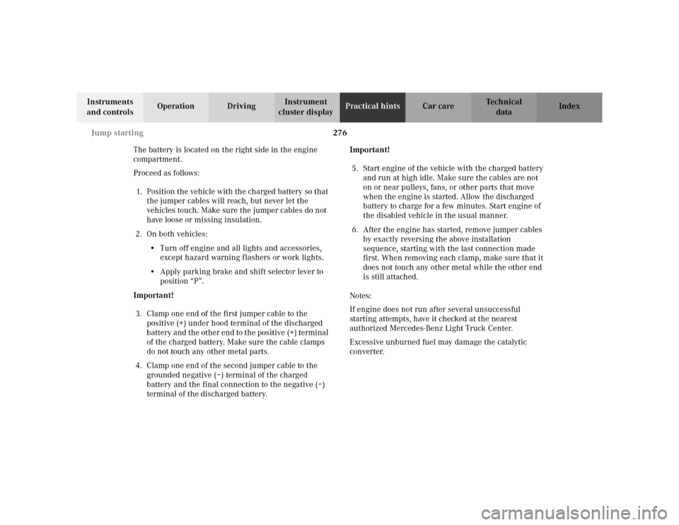
The battery is located on the right side in the engine
compartment.
Proceed as follows:
1. Position the vehicle with the charged battery so that
the jumper cables will reach, but never let the
vehicles touch. Make sure the jumper cables do not
have loose or missing insulation.
2. On both vehicles:
•Turn off engine and all lights and accessories,
except hazard warning flashers or work lights.
•Apply parking brake and shift selector lever to
position “P”.
Important!
3. Clamp one end of the first jumper cable to the
positive (+) under hood terminal of the discharged
battery and the other end to the positive (+) terminal
of the charged battery. Make sure the cable clamps
do not touch any other metal parts.
4. Clamp one end of the second jumper cable to the
grounded negative (–) terminal of the charged
battery and the final connection to the negative (–)
terminal of the discharged battery.Important!
5. Start engine of the vehicle with the charged battery
and run at high idle. Make sure the cables are not
on or near pulleys, fans, or other parts that move
when the engine is started. Allow the discharged
battery to charge for a few minutes. Start engine of
the disabled vehicle in the usual manner.
6. After the engine has started, remove jumper cables
by exactly reversing the above installation
sequence, starting with the last connection made
first. When removing each clamp, make sure that it
does not touch any other metal while the other end
is still attached.
Notes:
If engine does not run after several unsuccessful
starting attempts, have it checked at the nearest
authorized Mercedes-Benz Light Truck Center.
Excessive unburned fuel may damage the catalytic
converter.
Page 331 of 342

328 Index
Te ch n i c a l
data Instruments
and controlsOperation DrivingInstrument
cluster displayPractical hints Car careIndex
Instrument cluster ........................................................... 82
Activating display ....................................................... 86
Display illumination ................................................... 86
Indicator lamps ........................................................... 84
Malfunction and indicator lamps ...........................240
Instrument lamps ............................................................ 86
Instruments and controls ............................................... 18
Interior
General notes ............................................................. 132
Interior lighting ............................................................. 128
JJump starting ..................................................................275KKeys, changing batteries
in the electronic key ................................................. 292
Keys, vehicle ..................................................................... 24
LLamps, exterior .............................................................. 282
Additional turn signals on
the exterior mirror .............................................. 288
Adjusting headlamp aim ......................................... 290
Fog lamp assembly .................................................. 286
Fog lamps ................................................................... 103
Headlamp assembly .........................................283, 284
Headlamps ................................ 97, 283, 284, 290, 300
High mounted stop lamp ......................................... 289
License plate lamps ................................................. 289
Low and high beam ............................................ 97, 285
Parking lamp ...................................................... 97, 285
Replacing bulbs ........................................................ 282
Side marker lamp ..................................................... 285
Standing lamp ..................................................... 97, 285
Taillamp assemblies ................................................ 287
Turn signal lamp ................................................ 97, 285
Layout of poly-V-belt ..................................................... 308
Liftgate ............................................................................... 34
Unlocking .....................................................................27
Lighter ............................................................................. 138
Limp home mode
(Automatic transmission) ........................................ 190
Loading instructions ...................................................... 154