2002 MERCEDES-BENZ ML320 battery
[x] Cancel search: batteryPage 277 of 342
274 Battery
Te ch n i c a l
data Instruments
and controlsOperation DrivingInstrument
cluster displayPractical hintsCar care Index
Therefore, we strongly recommend that you have the
battery charge checked frequently, and corrected if
necessary, especially if you use the vehicle less than
approximately 200 miles (300 km) per month,
mostly for short distance trips, or if it is not used for
long periods of time.
Only charge a battery with a battery charger after the
battery has been disconnected from the vehicle’s
electrical circuit.
Always disconnect the battery negative lead first and
connect last.
When removing and connecting the battery, always
make sure that all electrical consumers are off and the
key is in steering lock position 0. The battery must
always be securely installed when the vehicle is in
operation. During removal and installation always
protect the disconnected battery positive (+) terminal
with the cover attached to the battery.
While the engine is running the battery terminal clamps
must not be loosened or detached, otherwise the
generator and other electronic components would be
damaged.Note:
The gear selector lever will remain locked in
position “P” and the electronic key cannot be turned in
the steering lock if the vehicle battery is disconnected
or discharged.
After reconnecting the battery also set the clock in
instrument cluster (see page 87), set date in trip
computer (see page 89), resynchronize the sliding / pop-
up roof (see page 294) and the electronic stability
program (ESP) (see page 224).
Battery recycling
Batteries contain material that can harm the
environment with improper disposal.
Large 12 Volt storage batteries contain lead.
Recycling of batteries is the preferred method of
disposal.
Many states require sellers of batteries to accept old
batteries for recycling.
Page 278 of 342
275 Jump starting
Te ch n i c a l
data Instruments
and controlsOperation DrivingInstrument
cluster displayPractical hintsCar care Index Jump startingImportant!
A discharged battery can freeze at approximately +14
°F
(–10
°C). In that case, it must be thawed out before
jumper cables are used. Attempting to jump start a
frozen battery can result in it exploding, causing
personal injury.
Jumper cable specifications:
•Minimum cable cross-section of 25 mm
2 or
approximately 2 AWG
•Maximum length of 11.5 ft. (3.5 m).
If the battery is discharged, the engine should be started
with jumper cables and the (12 V) battery of another
vehicle.
Only use 12 V battery to jump start your vehicle. Jump
starting with more powerful battery could damage the
vehicle’s electrical systems, which will not be covered
by the Mercedes-Benz Limited Warranty.
Wa r n i n g !
Failure to follow these directions will cause
damage to the electronic components, and can lead
to a battery explosion and severe injury or death.Never lean over batteries while connecting or jump
starting, you might get injured.Battery fluid contains sulfuric acid. Do not allow
this fluid to come in contact with eyes, skin or
clothing. In case it does, immediately flush affected
area with water, and seek medical help if
necessary.A battery will also produce hydrogen gas, which is
flammable and very explosive. Keep flames or
sparks away from battery, avoid improper
connection of jumper cables, smoking etc..Read all instructions before proceeding.
Page 279 of 342
276 Jump starting
Te ch n i c a l
data Instruments
and controlsOperation DrivingInstrument
cluster displayPractical hintsCar care Index
The battery is located on the right side in the engine
compartment.
Proceed as follows:
1. Position the vehicle with the charged battery so that
the jumper cables will reach, but never let the
vehicles touch. Make sure the jumper cables do not
have loose or missing insulation.
2. On both vehicles:
•Turn off engine and all lights and accessories,
except hazard warning flashers or work lights.
•Apply parking brake and shift selector lever to
position “P”.
Important!
3. Clamp one end of the first jumper cable to the
positive (+) under hood terminal of the discharged
battery and the other end to the positive (+) terminal
of the charged battery. Make sure the cable clamps
do not touch any other metal parts.
4. Clamp one end of the second jumper cable to the
grounded negative (–) terminal of the charged
battery and the final connection to the negative (–)
terminal of the discharged battery.Important!
5. Start engine of the vehicle with the charged battery
and run at high idle. Make sure the cables are not
on or near pulleys, fans, or other parts that move
when the engine is started. Allow the discharged
battery to charge for a few minutes. Start engine of
the disabled vehicle in the usual manner.
6. After the engine has started, remove jumper cables
by exactly reversing the above installation
sequence, starting with the last connection made
first. When removing each clamp, make sure that it
does not touch any other metal while the other end
is still attached.
Notes:
If engine does not run after several unsuccessful
starting attempts, have it checked at the nearest
authorized Mercedes-Benz Light Truck Center.
Excessive unburned fuel may damage the catalytic
converter.
Page 282 of 342
279 Towing
Te ch n i c a l
data Instruments
and controlsOperation DrivingInstrument
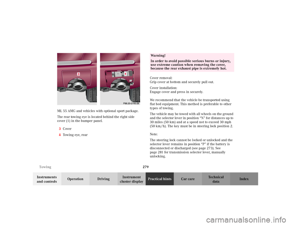
cluster displayPractical hintsCar care Index ML 55 AMG and vehicles with optional sport package.
The rear towing eye is located behind the right side
cover (1) in the bumper panel.
3Cover
4Tow i n g eye , r e a rCover removal:
Grip cover at bottom and securely pull out.
Cover installation:
Engage cover and press in securely.
We recommend that the vehicle be transported using
flat bed equipment. This method is preferable to other
types of towing.
The vehicle may be towed with all wheels on the ground
and the selector lever in position “N” for distances up to
30 miles (50 km) and at a speed not to exceed 30 mph
(50 km / h). The key must be in steering lock position 2.
Note:
The steering lock cannot be locked or unlocked and the
selector lever remains in position “P” if the battery is
disconnected or discharged (see page 273). See
page 281 for transmission selector lever, manually
unlocking.
Wa r n i n g !
In order to avoid possible serious burns or injury,
use extreme caution when removing the cover,
because the rear exhaust pipe is extremely hot.
Page 295 of 342
292 Remote control
Te ch n i c a l
data Instruments
and controlsOperation DrivingInstrument
cluster displayPractical hintsCar care Index
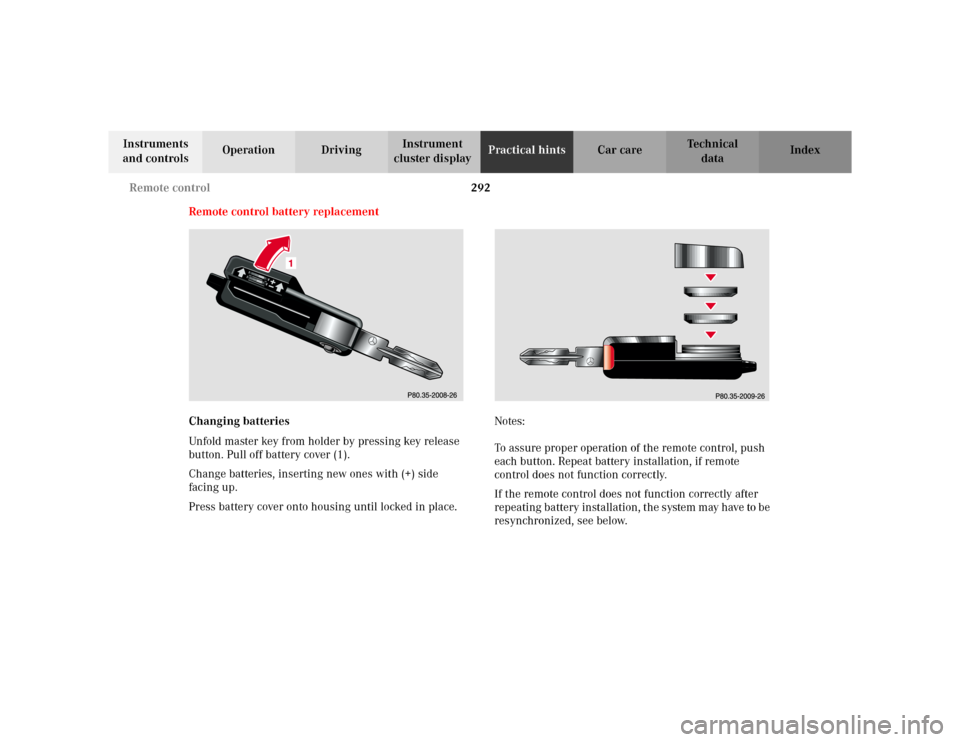
Remote control battery replacement
Changing batteries
Unfold master key from holder by pressing key release
button. Pull off battery cover (1).
Change batteries, inserting new ones with (+) side
facing up.
Press battery cover onto housing until locked in place.Notes:
To assure proper operation of the remote control, push
each button. Repeat battery installation, if remote
control does not function correctly.
If the remote control does not function correctly after
repeating battery installation, the system may have to be
resynchronized, see below.
Page 296 of 342
293 Remote control
Te ch n i c a l
data Instruments
and controlsOperation DrivingInstrument
cluster displayPractical hintsCar care Index Synchronizing remote control
If the remote control does not function correctly and the
batteries are in order, the system may have to be
resynchronized.
Turn key in steering lock to position 2, then to
position 0 and remove.
Within 10 seconds, push and hold button‹ while
pushing buttonΠfive times.
Release the button, and press‹, Œ orŠ once.
Check all functions. The remote control should once
again be operational.
Note:
If it is not possible to resynchronize the remote control,
have the system checked at your authorized Mercedes-
Benz Light Truck Center.Important!
Batteries contain materials that can harm the
environment if disposed of improperly. Recycling of
batteries is the preferred method of disposal. For
disposal, please follow manufacturer’s recommendation
on battery package.
Replacement Battery:
Lithium, type CR 2025 or equivalent.
Page 326 of 342
323 Index
Te ch n i c a l
data Instruments
and controlsOperation DrivingInstrument
cluster displayPractical hints Car careIndex Automatic transmission ............................................... 183
Emergency Operation .............................................. 190
Fluid level ...................................................................256
Selector lever position .............................................. 186
Transmission selector lever,
manually unlocking ............................................. 281
BBabySmart
TM airbag deactivation system ..................... 55
Self-test ......................................................................... 55
BAS (Brake assist system) ............................................ 217
Malfunction indicator lamp ..................................... 243
Battery .............................................................................273
Battery recycling ....................................................... 274
Charge indicator lamp ..............................................245
Battery, remote control ................................................. 292
Block heater .................................................................... 201
Blocking of rear door windows .................................... 124
Brake assist system (BAS) ............................................ 217
Malfunction indicator lamp ..................................... 243
Brake fluid .............................................................. 193, 316
Brake warning lamp ................................................. 241
Capacity ...................................................................... 315
Brake pad wear indicator ............................................. 247Brake warning lamp ...................................................... 241
Brake fluid low .......................................................... 241
Brakes ......................................................191, 193, 315, 316
Bulbs
See Replacing bulbs ................................................. 282
CCapacities
Fuels, coolants, lubricants etc. ............................... 314
Cargo area ....................................................................... 149
Hooks .......................................................................... 151
Loading instructions ................................................. 154
Cargo area cover blind .................................................. 155
Cargo compartment lamp ............................................. 129
Cargo floor plates
Removable .................................................................. 147
Storage ........................................................................ 148
Cargo tie-down rings ..................................................... 150
Catalytic converter ......................................................... 178
Cellular telephone .......................................................... 157
Center console .................................................................. 20
Central locking switch .................................................... 32
Page 334 of 342
331 Index
Te ch n i c a l
data Instruments
and controlsOperation DrivingInstrument
cluster displayPractical hints Car careIndex Rear seat head restraints .............................................. 143
Adjusting .................................................................... 143
Removal ...................................................................... 143
Rear view mirrors
Exterior ......................................................................... 77
Inside ............................................................................ 75
Rear window defroster .................................................. 121
Rear window wiper/washer ......................................... 106
Remote control ................................................................. 24
Battery replacement ................................................. 292
Changing batteries ................................................... 292
Operation ..................................................................... 26
Synchronizing remote control ................................ 293
Removable cargo floor plates ....................................... 147
Replacement keys ............................................................ 25
Replacing bulbs .............................................................. 282
Replacing wiper blade insert .......................................295
Reporting safety defects ................................................. 16
Residual engine heat utilization (REST) .....................117
Roadside assistance ......................................................... 10
Roadside assistance call
See Tele Aid ............................................................... 166
Roof rack .........................................................................296
SSafety guidelines for the seat belt, emergency
tensioning retractor and airbag ................................66
Screwdriver .................................................................... 259
Seat belt warning lamp ................................................ 245
Seat belts ...........................................................................48
Fastening ......................................................................50
Seat belt nonusage warning system .........................49
Unfastening .................................................................. 52
Warning lamp ........................................................... 245
Seat belts and integrated restraint system ..................48
Seat bench ....................................................................... 139
Seats, folding (Third row seats) ................................... 144
Seats, front ........................................................................ 38
Heated seats ................................................................. 46
Manual seats ................................................................40
Memory function .........................................................43
Power seats .................................................................. 41
Service indicator
See Flexible service system (FSS) ............................ 94
Side marker lamp .......................................................... 285
Sliding/pop-up roof ........................................................126
Emergency operation .............................................. 294
Express opening ........................................................127
Synchronizing .......................................................... 294