2002 MERCEDES-BENZ ML320 turn signal
[x] Cancel search: turn signalPage 101 of 342
98 Exterior lamp switch
Te ch n i c a l
data Instruments
and controlsOperationDrivingInstrument
cluster displayPractical hints Car care Index
Turn signal failure
If one of the turn signals fails, the turn signal indicator
system flashes and sounds at a faster than normal rate.Standing lamps
When the vehicle is parked on the street the standing
lamps (right or left side parking lamps) can be turned
on, making the vehicle more visible to passing vehicles.
The standing lamps cannot be operated with the key in
steering lock position 1 or 2.
Note:
With the key removed and a front door open, a warning
sounds if the vehicle’s exterior lamps (except standing
lamps) are not switched off.
Page 107 of 342
104 Hazard warning flasher
Te ch n i c a l
data Instruments
and controlsOperationDrivingInstrument
cluster displayPractical hints Car care Index
Hazard warning flasher switch
The hazard warning flasher switch is located on top of
the steering column.
The hazard warning flasher can be activated either
manually via the switch located in the dashboard, or it
is activated automatically at the time an airbag is
deployed.
To activate hazard warning flasher, press switch once.
To deactivate, press switch again.
Note:
To signal turns while being towed with hazard warning
flasher in use, turn key in steering lock to position 2
and activate combination switch for left or right turn
signal in usual manner. Now deactivate the hazard
warning flasher, only the selected turn signal will
operate. Upon canceling the turn signal, the hazard
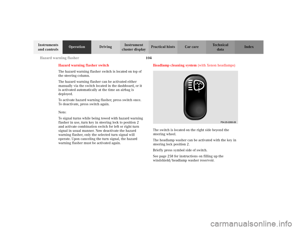
warning flasher must be activated again.Headlamp cleaning system (with Xenon headlamps)
The switch is located on the right side beyond the
steering wheel.
The headlamp washer can be activated with the key in
steering lock position 2.
Briefly press symbol side of switch.
See page 258 for instructions on filling up the
windshield / headlamp washer reservoir.
Page 162 of 342
159 Garage door opener
Te ch n i c a l
data Instruments
and controlsOperationDrivingInstrument
cluster displayPractical hints Car care Index For operation in the USA only: This device complies
with Part 15 of the FCC Rules. Operation is subject to
the following two conditions:
(1) This device may not cause harmful interference, and
(2) this device must accept any interference received,
including interference that may cause undesired
operation.
Any unauthorized modification to this device could void
to the user’s authority to operate the equipment.
Programming or reprogramming the integrated
remote control:
1. Turn key in steering lock to position 1 or 2.
2. Hold the end of the hand-held transmitter of the
device you wish to train approximately 2 to 5 inches
(5 cm to 12 cm) away from the surface of the
integrated remote control located on the overhead
console, keeping the indicator lamp in view.3. Using both hands, simultaneously push the hand-
held transmitter button and the desired integrated
remote control button. Do not release the buttons
until completing step 4.
4. The indicator lamp on the integrated remote control
will flash, first slowly and then rapidly. When the
indicator lamp flashes rapidly, both buttons may be
released (the rapid flashing lamp indicates
successful programming of the new frequency
signal). To program the remaining two buttons,
follow steps 1 through 4.
Note:
If after repeated attempts, you do not successfully
program the integrated remote control device to learn
the signal of the hand-held transmitter, the garage door
opener could be equipped with the “rolling code
feature”.
Page 164 of 342
161 Garage door opener
Te ch n i c a l
data Instruments
and controlsOperationDrivingInstrument
cluster displayPractical hints Car care Index Operation of remote control:
1. Turn key in steering lock to position 1 or 2.
2. Select and press the appropriate button to activate
the remote controlled device. The integrated remote
control transmitter continues to send the signal as
long as the button is pressed – up to 20 seconds.Erasing the remote control memory:
1. Turn key in steering lock to position 1 or 2.
2. Simultaneously holding down the left and right side
buttons for approximately 20 seconds, or until the
control lamp blinks rapidly, will erase the codes of
all three channels.
Page 174 of 342
171 Tele Aid
Te ch n i c a l
data Instruments
and controlsOperationDrivingInstrument
cluster displayPractical hints Car care Index When the connection is established, the message
“ROADSIDE ASSISTANCE – CALL CONNECTED”
appears in the MCS display. The Tele Aid system will
transmit data generating the vehicle identification
number, model, color and location (subject to
availability of cellular and GPS signals).
While the call is connected, you can change to
navigation menu by pressing NAVI button on the MCS.
A voice connection between the Roadside Assistance
dispatcher and the occupants of the vehicle will be
established. When a voice connection is established the
audio system mutes and the message “TELE AID –
ROADSIDE ASSISTANCE CALL ACTIVE” appears in the
MCS display. The nature of the need for assistance can
then be described. The Mercedes-Benz Roadside
assistance dispatcher will either dispatch a qualified
Mercedes-Benz technician or arrange to tow your
vehicle to the nearest Mercedes-Benz Center. For
services such as labor and/or towing charges may apply.
Refer to the Roadside Assistance manual for more
information.These programs are only available in the USA:
•Sign and Drive services: Services such as jump start,
a few gallons of fuel or the replacement of a flat tire
with the vehicle spare tire are obtainable,
•Remote Vehicle Diagnostics: This function permits
the Mercedes-Benz Roadside Assistance dispatcher
to download malfunction codes and actual vehicle
data.
Notes:
The indicator lamp in the Roadside Assistance
button• remains illuminated in red for
approximately 10 seconds during the system self-check
after turning key in steering lock to position 2 (together
with the “SOS” button and the Information
button¡).
See system self-check on page 166 when the indicator
lamp does not light up in red or stay on longer than
approximately 10 seconds.
Page 176 of 342
173 Tele Aid
Te ch n i c a l
data Instruments
and controlsOperationDrivingInstrument
cluster displayPractical hints Car care Index The Tele Aid system will transmit data generating the
vehicle identification number, model, color and location
(subject to availability of cellular and GPS signals).
While the call is connected, you can change to
navigation menu by pressing NAVI button on the MCS.
A voice connection between the Customer Assistance
Center representative and the occupants of the vehicle
will be established. When a voice connection is
established, the audio system mutes and the message
“TELE AID – INFO CALL ACTIVE” appears in the MCS
display. Information regarding the operation of your
vehicle, the nearest Mercedes-Benz Light Truck Center
or Mercedes-Benz USA products and services is
available to you.
For more details concerning Tele Aid, please visit
www.mbusa.com and use your ID and password, sent to
you separately, to learn more (USA only).Notes:
The indicator lamp in the Information button¡
remains illuminated in red for approximately
10 seconds during the system self-check after turning
key in steering lock to position 2 (together with the
“SOS” button and the Roadside Assistance button•).
See system self-check on page 166 when the indicator
lamps do not light up in red or stay on longer than
approximately 10 seconds.
If the indicator lamp in the Information button¡ is
illuminated continuously and there was no voice
connection to the Response Center established, then the
Tele Aid system could not initiate an Roadside
Assistance call (e.g. the relevant cellular phone network
is not available). The message “Info – CALL FAILED”
appears in the MCS display.
Should this occur, information must be summoned by
other means.
Information calls can be terminated using the END
button on the MCS unit.
Page 214 of 342
211 Driving instructions
Te ch n i c a l
data Instruments
and controlsOperationDrivingInstrument
cluster displayPractical hints Car care Index Checking weights of vehicle and trailer
To assure that the tow vehicle and trailer are in
compliance with the maximum permissible weight
limits, and to know the actual weights, have the loaded
rig (tow vehicle including driver, passengers and cargo,
trailer fully loaded) weighed on a commercial scale.
Check the vehicle’s front and rear Gross Axle Weight
(GAW), the GTW and TW. The values as measured must
not be exceeded, according to the weight listed under
“Vehicle and trailer weight and ratings”.
Attaching a trailer
Please observe maximum permitted trailer dimensions
(width and length).
Most states and all Canadian provinces require safety
chains between your tow vehicle and the trailer. The
chains should be crisscrossed under the trailer tongue.
They must be attached to the hitch receiver, and not to
the vehicle’s bumper or axle. Be sure to leave enough
slack in the chains to permit turning corners.
Most states and all Canadian provinces require a
separate brake system at various trailer weights.Caution!
Do not connect a trailer brake system (if trailer is so
equipped) directly to the vehicle’s hydraulic brake
system, as your vehicle is equipped with antilock
brakes. If you do, neither the vehicle’s brakes nor the
trailer’s brakes will function properly.
The provided vehicle electrical wiring harness for trailer
towing has a brake signal wire (color orange) for
hook-up to a brake controller.
Most states and all Canadian provinces require a
break-away switch on trailers with a separate brake
system. The switch activates the trailer brakes in the
possible event that the trailer might separate from the
tow vehicle.
You should consider using a trailer sway control system.
For further information see your authorized
Mercedes-Benz Light Truck Center.
Page 237 of 342

234 Parking system
Te ch n i c a l
data Instruments
and controlsOperationDrivingInstrument
cluster displayPractical hints Car care Index
All yellow and one or both red segments light up.
Additionally, there is an acoustic warning lasting
approximately 3 seconds.
The obstacle may not be recognized if outside the
shaded sensor field, and no longer be indicated when
approaching it any closer (warning indicators go out).
Parktronic malfunction
All red segments of the warning indicators light up, and
a warning sounds for 3 seconds, if Parktronic does not
function properly.
A dirty sensor or other ultrasonic signals could be the
reason. See page 301 for instructions on cleaning the
sensors in the bumpers.
After cleaning the sensors, turn electronic key in
steering lock to position 2. If a malfunction continues to
be displayed, have the system checked at your
authorized Mercedes-Benz Center.Parktronic switch
The switch is located on the center console.
1Parktronic switched off
2Parktronic switched on
3Indicator lamp – comes on when Parktronic is
switched off
The parktronic system is switched on again when
turning the electronic key in steering lock position 2.3