Page 273 of 342
270 Tires, Wheels
Te ch n i c a l
data Instruments
and controlsOperation DrivingInstrument
cluster displayPractical hintsCar care Index
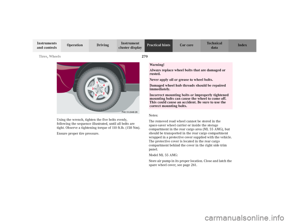
Using the wrench, tighten the five bolts evenly,
following the sequence illustrated, until all bolts are
tight. Observe a tightening torque of 110 ft.lb. (150 Nm).
Ensure proper tire pressure.Notes:
The removed road wheel cannot be stored in the
space-saver wheel carrier or inside the storage
compartment in the rear cargo area (ML 55 AMG), but
should be transported in the rear cargo compartment
wrapped in a protective cover supplied with the vehicle.
The protective cover is located in the rear cargo
compartment behind the cover in the right side trim
panel.
Model ML 55 AMG:
Store air pump in its proper location. Close and latch the
spare wheel cover, see page 261.
1
2
3
4
5
P40.10-2446-26
Wa r n i n g !
Always replace wheel bolts that are damaged or
rusted.Never apply oil or grease to wheel bolts.Damaged wheel hub threads should be repaired
immediately.Incorrect mounting bolts or improperly tightened
mounting bolts can cause the wheel to come off.
This could cause an accident. Be sure to use the
correct mounting bolts.
Page 277 of 342
274 Battery
Te ch n i c a l
data Instruments
and controlsOperation DrivingInstrument
cluster displayPractical hintsCar care Index
Therefore, we strongly recommend that you have the
battery charge checked frequently, and corrected if
necessary, especially if you use the vehicle less than
approximately 200 miles (300 km) per month,
mostly for short distance trips, or if it is not used for
long periods of time.
Only charge a battery with a battery charger after the
battery has been disconnected from the vehicle’s
electrical circuit.
Always disconnect the battery negative lead first and
connect last.
When removing and connecting the battery, always
make sure that all electrical consumers are off and the
key is in steering lock position 0. The battery must
always be securely installed when the vehicle is in
operation. During removal and installation always
protect the disconnected battery positive (+) terminal
with the cover attached to the battery.
While the engine is running the battery terminal clamps
must not be loosened or detached, otherwise the
generator and other electronic components would be
damaged.Note:
The gear selector lever will remain locked in
position “P” and the electronic key cannot be turned in
the steering lock if the vehicle battery is disconnected
or discharged.
After reconnecting the battery also set the clock in
instrument cluster (see page 87), set date in trip
computer (see page 89), resynchronize the sliding / pop-
up roof (see page 294) and the electronic stability
program (ESP) (see page 224).
Battery recycling
Batteries contain material that can harm the
environment with improper disposal.
Large 12 Volt storage batteries contain lead.
Recycling of batteries is the preferred method of
disposal.
Many states require sellers of batteries to accept old
batteries for recycling.
Page 280 of 342
277 Towing
Te ch n i c a l
data Instruments
and controlsOperation DrivingInstrument
cluster displayPractical hintsCar care Index Towing the vehicle
Important!
When towing the vehicle, please, note the following:
With the automatic central locking activated and the
engine running, the vehicle doors lock if the left front
wheel is turning at vehicle speeds of approximately
9 mph (15 km / h) or more.
To prevent the vehicle door locks from locking,
deactivate the automatic central locking, see page 33.The front towing eye is located on the passenger side
below the bumper.
1Towin g eye, fr on t
Wa r n i n g !
Prior to towing the vehicle with all wheels on the
ground, make certain that the key is in steering
lock position 2.
P88.20-2191-26
Page 282 of 342
279 Towing
Te ch n i c a l
data Instruments
and controlsOperation DrivingInstrument
cluster displayPractical hintsCar care Index ML 55 AMG and vehicles with optional sport package.
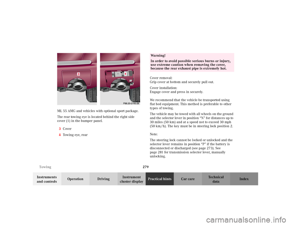
The rear towing eye is located behind the right side
cover (1) in the bumper panel.
3Cover
4Tow i n g eye , r e a rCover removal:
Grip cover at bottom and securely pull out.
Cover installation:
Engage cover and press in securely.
We recommend that the vehicle be transported using
flat bed equipment. This method is preferable to other
types of towing.
The vehicle may be towed with all wheels on the ground
and the selector lever in position “N” for distances up to
30 miles (50 km) and at a speed not to exceed 30 mph
(50 km / h). The key must be in steering lock position 2.
Note:
The steering lock cannot be locked or unlocked and the
selector lever remains in position “P” if the battery is
disconnected or discharged (see page 273). See
page 281 for transmission selector lever, manually
unlocking.
Wa r n i n g !
In order to avoid possible serious burns or injury,
use extreme caution when removing the cover,
because the rear exhaust pipe is extremely hot.
Page 283 of 342
280 Towing
Te ch n i c a l
data Instruments
and controlsOperation DrivingInstrument
cluster displayPractical hintsCar care Index
To be certain to avoid additional damage to the vehicle
powertrain, however you should do the following:
•With damage to front axle, raise front axle. Remove
flexible drive shaft between rear axle and transfer
case
•With damage to rear axle, raise rear axle and tow
vehicle with wheel lift or dolly placed under front
wheels.
•With damage to transfer case, remove flexible drive
shafts to the drive axles.
Note:
Always install new self-locking nuts when reinstalling
the flexible drive shaft.Caution!
If the vehicle is towed with the front axle raised, the
engine must be shut off (key in steering lock position 1).
Otherwise, the 4-ETS+ may become engaged which may
cause loss of towing control. Switch off the tow-away
alarm (see page 37) as well as the ESP (see page 225).
Note:
To signal turns while being towed with hazard warning
flasher in use, turn key in steering lock to position 2
and activate combination switch for left or right turn
signal in usual manner. Now deactivate the hazard
warning flasher, only the selected turn signal will
operate. Upon canceling the turn signal, the hazard
warning flasher must be activated again.
Wa r n i n g !
With the engine not running, there is no power
assistance for the braking and steering systems. In
this case, it is important to keep in mind that a
considerably higher degree of effort is necessary to
brake and steer the vehicle.
Page 285 of 342
282 Exterior lamps
Te ch n i c a l
data Instruments
and controlsOperation DrivingInstrument
cluster displayPractical hintsCar care Index
Exterior lamps
Headlamp adjustment
Correct headlamp adjustment is extremely important.
Check and readjust headlamps at regular intervals and
when a bulb has been replaced.
For adjusting headlamp aim see page 290.Replacing bulbs
To prevent a possible electrical short circuit, switch off
lamp prior to replacing a bulb.
When replacing bulbs, install only 12 volt bulbs with
the specified watt rating.
When replacing halogen bulbs do not touch glass
portion of bulb with bare hands. Use plain paper or a
clean cloth.
Wa r n i n g !
Bulbs and bulb holders can be very hot. Allow the
lamp to cool down before changing a bulb.
Halogen lamps contain pressurized gas. A bulb can
explode if you:
• touch or move it when hot,
•drop the bulb,
• scratch the bulb.Wear eye and hand protection.
Wa r n i n g !
Because of high voltage in BiXenon lamps, it is
dangerous to replace the bulb of repair the lamp
and its components. We recommend that you have
such work done by a qualified technician.
Page 294 of 342
291 Exterior lamps
Te ch n i c a l
data Instruments
and controlsOperation DrivingInstrument
cluster displayPractical hintsCar care Index 5. (High beams on):
Simultaneously turn adjusting screws (1 and 2 on
page 283 or 284) counterclockwise to adjust
headlamp downward, clockwise upward.
Graduations:
screw 1: 0.50
° pitch,
screw 2: 0.67° pitch.
6. Horizontal headlamp aim (High beams on):
Turn adjusting screw (2) (left headlamp:
counterclockwise to adjust to the left, clockwise to
the right [right headlamp in opposite direction])
until the headlamp (high beam pattern) is centered
about the vertical centerline (1) as shown.
The left and right headlamps must be adjusted
individually.
Graduations: 0.33
° pitch.Note:
If it is not possible to obtain a proper headlamp
adjustment, have the system checked at your authorized
Mercedes-Benz Light Truck Center.
Page 297 of 342

294 Emergency operation of sliding/pop-up roof
Te ch n i c a l
data Instruments
and controlsOperation DrivingInstrument
cluster displayPractical hintsCar care Index
Emergency operation of sliding/pop-up roof
The sliding / pop-up roof can be opened or closed
manually should an electrical malfunction occur.
The sliding / pop-up roof drive is located behind the
cover between the front interior lamps.
1. Open cover by using a flat blade screw driver at top
edge.
2. Obtain crank (supplied with vehicle) and insert in
hexagon drive hole, located at rear end of the open
cover.Note:
Push crank upward while turning it, to disengage the
electric motor.
To slide the roof closed or to raise the roof at the rear:
turn crank clockwise.
To slide the roof open or to lower the roof at the rear:
turn crank counterclockwise.
Synchronizing the sliding / pop-up roof
After manually operating the sliding / pop-up roof, a
timing synchronization is needed for future electrical
operation of the roof. To do so, remove fuse for sliding/
pop-up roof operation, located in fuse box, for one
second and reinstall. Now push and hold switch until
the sliding / pop-up roof is fully raised. Continue to hold
switch for another second.
For notes on fuses, see page 250.
RESETMODEMODE