2002 MERCEDES-BENZ G500 locking
[x] Cancel search: lockingPage 232 of 385
229 Driving instructions
Te ch n i c a l
data Instruments
and controlsOperationDrivingInstrument
cluster displayPractical hints Car care Index Traction in steep terrain:
Be easy on the accelerator and watch for continuous
wheel traction when driving in steep terrain.
When the differential locks are not engaged, 4-ETS
helps greatly when starting out on a steep incline. The
front wheels have then the tendency to slip due to the
weight reduction over the front axle. The ETS
recognizes the situation and limits the torque for the
front wheels by braking them. Simultaneously the
torque for the rear wheels is increased.
See page 241 for four wheel electronic traction system
(4-ETS).
Driving across a hilltop:
To prevent the vehicle from speeding up too much after
climbing a hill, decelerate just ahead of a hilltop (do not
select gear range “N”). Use the momentum of the
vehicle to drive across the hilltop. Driving in this
manner prevents the vehicle from jumping across the
hilltop and thus loosing its forward momentum.
Driving downhill:
Select gear range “1” on the automatic transmission,
see page 207.Drive downhill observing the same rules as driving
uphill.
Driving on embankments, slopes and other steep
inclines should only be done straight up or downhill, i.e.
in the line of gravity.
Do not drive along the side of a slope (danger of vehicle
rollover). If in doing so, the vehicle begins to show a
tendency to roll, immediately steer into a line of gravity
(straight up or downhill).
Utilize the engine’s braking power when descending a
slope, observe the engine speed (do not overrev the
engine). Apply the service brake as needed.
The special LOW range ABS setting allows for precise
and brief (cyclical) blocking of the front wheels,
permitting them to dig into loose ground. Remember
that the front wheels when stopped, slide across a
surface, thus loose their ability to steer the vehicle.
Check the brakes after a lengthy downgrade drive.
Important!
Only apply the service brake if the vehicle travels
straight downhill, i.e. in the line of gravity.
J_G463.book Seite 229 Mittwoch, 19. September 2001 8:06 08
Page 242 of 385
239 Driving systems
Te ch n i c a l
data Instruments
and controlsOperationDrivingInstrument
cluster displayPractical hints Car care Index Antilock brake system (ABS)
Important!
The ABS improves steering control of the vehicle during
hard braking maneuvers.
The ABS prevents the wheels from locking up above a
vehicle speed of approximately 5 mph (8 km / h)
independent of road surface conditions.
At the instant one of the wheels is about to lock up, a
slight pulsation can be felt in the brake pedal,
indicating that the ABS is in the regulating mode. Keep
firm and steady pressure on the brake pedal while
experiencing the pulsation.
Continuous steady brake pedal pressure results in
applying the advantages of the ABS, namely braking
power and ability to steer the vehicle.In the case of an emergency brake maneuver keep
continuous full pressure on the brake pedal. In this
manner only can the ABS be most effective.
On slippery road surfaces, the ABS will respond even
with light brake pedal pressure because of the
increased likelihood of locking wheels. The pulsating
brake pedal can be an indication of hazardous road
conditions and functions as a reminder to take extra
care while driving.
ABS control
The ABS malfunction indicator lamp- in the
instrument cluster comes on with the electronic key in
starter switch position 2 and should go out with the
engine running.
When the ABS malfunction indicator lamp- in the
instrument cluster comes on while the engine is
running, it indicates that the ABS has detected a
malf un ction an d has s witched of f . In t his c ase, t he brake
system functions in the usual manner, but without
antilock assistance.
With the ABS malfunctioning, the BAS, ESP and 4-ETS
are also switched off. The malfunction indicator lamps
come on with the engine running.
Wa r n i n g !
Do not pump the brake pedal, rather use firm,
steady brake pedal pressure. Pumping the brake
pedal defeats the purpose for ABS and significantly
reduces braking effectiveness.
J_G463.book Seite 239 Mittwoch, 19. September 2001 8:06 08
Page 298 of 385
295 Contents - Practical hints
Te ch n i c a l
data Instruments
and controlsOperation DrivingInstrument
cluster displayPractical hintsCar care Index
Practical hintsFirst aid kit, vehicle tools
and jack ......................................296
CD-changer .....................................296
Fuses ................................................297
Electrical outlet .............................. 301
Stowing items in the vehicle ........ 301
Hood .................................................302
Checking engine oil level .............304
Automatic transmission
fluid level ...................................305
Engine oil consumption ................305
Coolant level ...................................306
Adding coolant ...........................306
Windshield washer/headlamp
cleaning system .........................307
Windshield and headlamp
washer fluid mixing ratio .........307Vehicle jack .................................... 308
Wheels ............................................. 310
Tire replacement ........................ 310
Rotating wheels .......................... 311
Spare wheel cover ..........................312
Spare wheel ..................................... 313
Changing wheels ............................ 314
Tire inflation pressure .................. 318
Battery .............................................. 319
Jump starting ................................. 321
Towing the vehicle ........................ 324
Transmission selector lever,
manually unlocking .................. 327
Stranded vehicle ............................ 327
Exterior lamps ............................... 328
Headlamp assembly .................. 329
Fog lamp, front ........................... 332
Turn signal lamp, front ............ 334Turn signal lamp, side ...............335
Front and rear
side marker lamps .....................337
Taillamp assemblies ..................339
License plate lamp .....................340
Rear fog lamp / Backup lamp ... 341
Changing batteries in
the electronic key .....................343
Synchronizing
remote control ............................345
Emergency operation of
sliding/pop-up roof ...................346
Manual release for
fuel filler flap .............................347
Replacing wiper blades .................348
J_G463.book Seite 295 Mittwoch, 19. September 2001 8:06 08
Page 318 of 385
315 Tires, Wheels
Te ch n i c a l
data Instruments
and controlsOperation DrivingInstrument
cluster displayPractical hintsCar care Index Move vehicle to a level area which is a safe distance
from the roadway.
Important!
The vehic le door s lock if t he lef t f ron t wheel r otate s with
the engine running. Do not leave the engine running
while changing a wheel.
1. Set parking brake and turn on hazard warning
flasher.
2. Move selector lever to position “P” and turn off
engine, and remove key from the starter switch.
Lock steering wheel with wheels in straight ahead
position.
3. Prevent vehicle from rolling away by blocking
wheels with wheel chocks (not supplied with
vehicle) or sizable wood block or stone. When
changing a wheel on a hill, place chocks on the
downhill side blocking both wheels of the other
axle. On a level road, place one chock in front of and
one behind the wheel that is diagonally opposite to
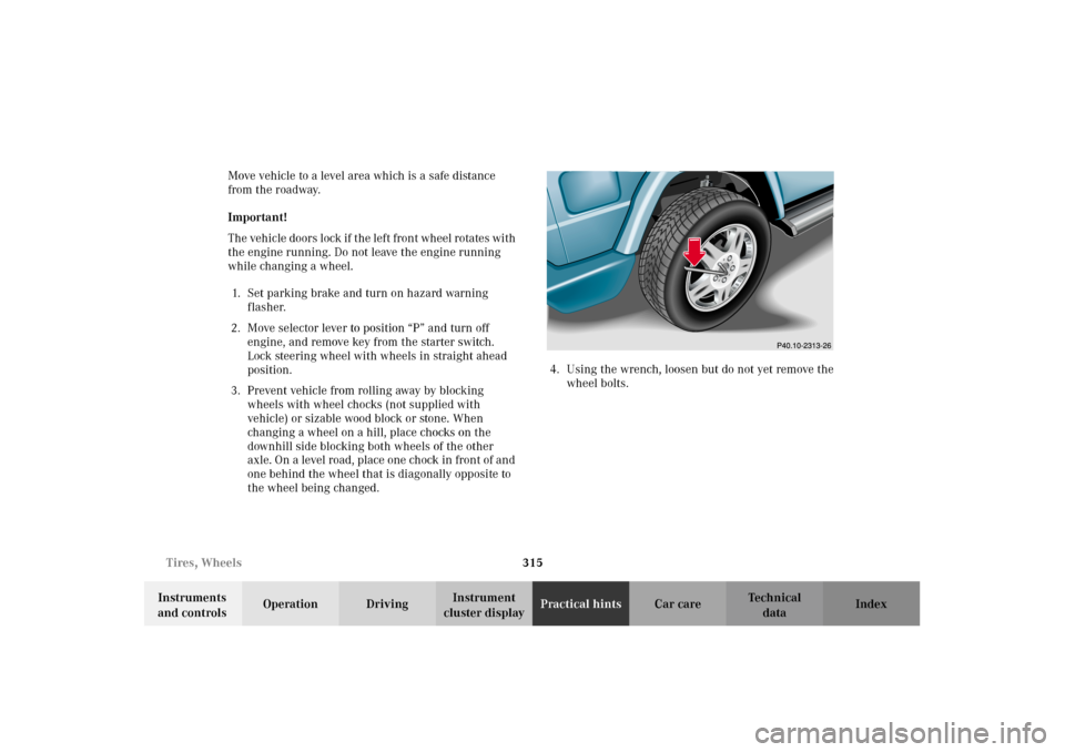
the wheel being changed.4. Using the wrench, loosen but do not yet remove the
wheel bolts.
J_G463.book Seite 315 Mittwoch, 19. September 2001 8:06 08
Page 327 of 385
324 Towing
Te ch n i c a l
data Instruments
and controlsOperation DrivingInstrument
cluster displayPractical hintsCar care Index
Towing the vehicle
Notes:
The selector lever will remain locked in position “P” and
the electronic key cannot be turned in the starter switch
if the battery is disconnected or discharged. See battery
on page 319 or jump starting on page 321.
In order to move the vehicle, shift automatic
transmission to position “N”.
Transmission selector lever, manually unlocking, see
page 327.Important!
When towing the vehicle, please, note the following:
Towing of the vehicle should only be done using the
properly installed towing eye bolt. Never attach tow
cable, tow rope or tow rod to vehicle chassis, frame
or suspension parts.
The vehicle may be towed with all wheels on the
ground and the selector lever in position “N” for
distances up to 30 miles (50 km) and at a speed not
to exceed 30 mph (50 km / h). The key must be in
starter switch position 2.
With the automatic central locking activated and the
engine running, the vehicle doors lock if the left front
wheel is turning at vehicle speeds of approximately
9 mph (15 km / h) or more.
To prevent the vehicle door locks from locking,
deactivate the automatic central locking. See the
individual setting menu “VEHICLE” – “AUTOMATIC
DOOR LOCK” on page 118.
We recommend that the vehicle be transported using
flat bed equipment. This method is preferable to other
types of towing.
To prevent damage during transport, do not tie down
vehicle by its chassis or suspension parts.
Prior to towing the vehicle with all wheels on the
ground, make certain that the electronic key is in
starter switch position 2.If the electronic key is left in the starter switch
position 0 for an extended period of time, it can no
longer be turned in the switch. In this case, the
steering is locked. To unlock, remove electronic key
from starter switch and reinsert.
With the engine not running, there is no power
assistance for the braking and steering systems. In
this case, it is important to keep in mind that a
considerably higher degree of effort is necessary to
brake and steer the vehicle.
J_G463.book Seite 324 Mittwoch, 19. September 2001 8:06 08
Page 329 of 385
326 Towing
Te ch n i c a l
data Instruments
and controlsOperation DrivingInstrument
cluster displayPractical hintsCar care Index
Engine damage /Transmission damage,
Electrical malfunction
To be certain to avoid additional damage to the vehicle
powertrain, however you should do the following:
Shift automatic transmission to position “N”.
Important!
Vehicle may be towed for distances up to 30 miles
(50 km) and at a speed not to exceed 30 mph
(50 km/h).
For towing vehicle for distances exceeding 30 miles
(50 km) or if the vehicle has a damaged transfer
case, remove drive shafts to the drive axles.
When towing vehicle with one axle raised, the
electronic key in starter switch must be in
position 1.
With damage to front axle, raise front axle. Remove
drive shaft between rear axle and transfer case.
With damage to rear axle, raise rear axle and tow
vehicle with wheel lift or dolly placed under front
wheels.Notes:
When removing drive shaft, place M10 nuts on bolts as
distance sleeves and tighten using M8 nuts.
Always install new self-locking nuts when reinstalling
the drive shaft.
Caution!
If the vehicle is towed with the front axle raised, the
engine must be shut off (electronic key in starter switch
position 1). Otherwise, the 4-ETS may become engaged
which may cause loss of towing control. Switch off the
tow-away alarm (see page 43) as well as the ESP (see
page 245).
Note:
To signal turns while being towed with hazard warning
flasher in use, turn electronic key in starter switch to
position 1 and activate combination switch for left or
right turn signal in usual manner. Now deactivate the
hazard warning flasher, only the selected turn signal
will operate. Upon canceling the turn signal, the hazard
warning flasher must be activated again.
J_G463.book Seite 326 Mittwoch, 19. September 2001 8:06 08
Page 330 of 385
327 Towing
Te ch n i c a l
data Instruments
and controlsOperation DrivingInstrument
cluster displayPractical hintsCar care Index Transmission selector lever, manually unlocking
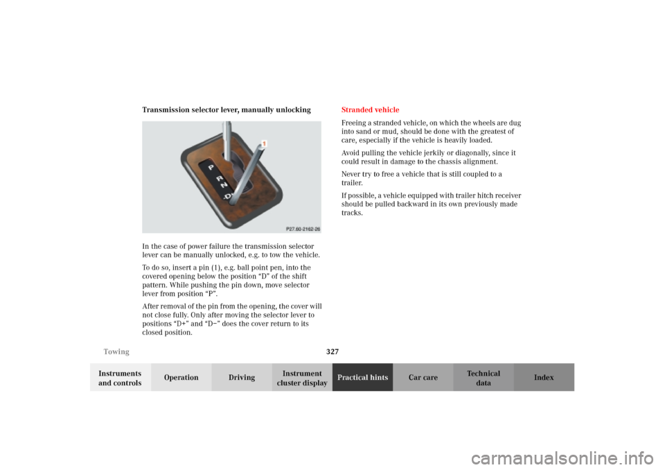
In the case of power failure the transmission selector
lever can be manually unlocked, e.g. to tow the vehicle.
To do so, insert a pin (1), e.g. ball point pen, into the
covered opening below the position “D” of the shift
pattern. While pushing the pin down, move selector
lever from position “P”.
After removal of the pin from the opening, the cover will
not close fully. Only after moving the selector lever to
positions “D+” and “D–” does the cover return to its
closed position.Stranded vehicle
Freeing a stranded vehicle, on which the wheels are dug
into sand or mud, should be done with the greatest of
care, especially if the vehicle is heavily loaded.
Avoid pulling the vehicle jerkily or diagonally, since it
could result in damage to the chassis alignment.
Never try to free a vehicle that is still coupled to a
trailer.
If possible, a vehicle equipped with trailer hitch receiver
should be pulled backward in its own previously made
tracks.
J_G463.book Seite 327 Mittwoch, 19. September 2001 8:06 08
Page 346 of 385
343 Electronic main key
Te ch n i c a l
data Instruments
and controlsOperation DrivingInstrument
cluster displayPractical hintsCar care Index Changing batteries in the electronic key
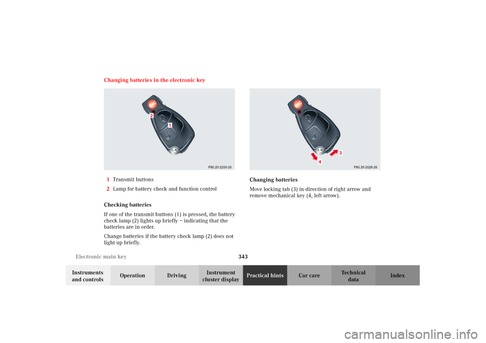
1Transmit buttons
2Lamp for battery check and function control
Checking batteries
If one of the transmit buttons (1) is pressed, the battery
check lamp (2) lights up briefly – indicating that the
batteries are in order.
Change batteries if the battery check lamp (2) does not
light up briefly.Changing batteries
Move locking tab (3) in direction of right arrow and
remove mechanical key (4, left arrow).
P80.20-2200-26
1
2
P80.35-2028-26
4
3
J_G463.book Seite 343 Mittwoch, 19. September 2001 8:06 08