2002 MERCEDES-BENZ G500 power steering
[x] Cancel search: power steeringPage 247 of 385
244 Driving systems
Te ch n i c a l
data Instruments
and controlsOperationDrivingInstrument
cluster displayPractical hints Car care Index
If the ESP warning lampv comes on continuously
and warning messages appears in the multifunction
display with the engine running, a malfunction has
been detected in either system. Only partial engine
output will be available.
If the BAS malfunctions, the brake system functions in
the usual manner, but without BAS, ESP and 4-ETS.
If the ESP warning lampv and the
Émalfunction indicator lamp come on and warning
messages appears in the multifunction display, have the
BAS or ESP checked at your authorized Mercedes-Benz
Light Truck Center as soon as possible.
With the ABS malfunctioning, the BAS, ESP and 4-ETS
are also switched off.
For warn in g m ess ages and malfun ction in d icator lamps ,
see page 264 and page 272.
Driving the vehicle with varied size tires will cause the
wheels to rotate at different speeds, therefore the ESP
may activate (yellow ESP warning lampv in
speedometer dial comes on). For this reason, all wheels,
including the spare wheel, must have the same tire
outside diameter.When testing the parking brake on a brake test
dynamometer, the engine must be shut off. Otherwise,
the ESP will immediately be engaged and will apply the
rear wheel brakes.
In winter operation, the maximum effectiveness of the
ESP is on ly achieved wit h Me rced es -B enz re comm end ed
M+S rated radial-ply tires and / or snow chains.
Synchronizing ESP
If the power supply was interrupted (battery
disconnected or empty), the ESP warning lampv
and warning messages appears in the multifunction
display with the engine running.
Turn steering wheel completely to the left and then to
the right. The ESP warning lampv and the warning
messages in the multifunction display should go out.
J_G463.book Seite 244 Mittwoch, 19. September 2001 8:06 08
Page 254 of 385
251 Driving systems
Te ch n i c a l
data Instruments
and controlsOperationDrivingInstrument
cluster displayPractical hints Car care Index A few words about differentials and differential
locks
When a vehicle negotiates a turn, wheels on the outside
of the curve must travel farther and rotate faster than
the inside wheels. The differential, the operation of a set
of gears that allow the powered wheels in a vehicle to
turn a different speeds, provides for this essential
function.
The drawback is that the differential also sends most of
the engine's power to the wheel with the least load or
strain on it. For example, if one of a vehicle's powered
wheels sits on a patch of snow and spins because there
is no traction, all of the engine's power will go to that
wheel because the power will take the path of least
resistance. Meanwhile, the opposite wheel, sitting on
dry pavement where it could get enough grip to start the
vehicle moving, sits idle because it gets no power.
The Electronic Traction System (ETS) addresses this
problem and provides for good control and steering
ability by automatically slowing the slipping wheel and
thus increasing the power to the other non-slipping
d rive whee ls to get t he ve hicle m ovin g. The ESP and ETS
in this vehicle feature such intelligent limited-slip
differential technology, ideally suited for on-road and light off-road driving. The position “LOW” of the
transfer case (see pages 247and 226) also enhances
off-road driving capabilities.
More extreme off-road conditions may call for another
cure which is to engage a differential lock, preventing
the differential from operating altogether. This vehicle
offers as standard equipment three differential locks:
front, transfer case (center), and rear. Each can be
engaged simply by pushing a dashboard-mounted
button (see pages 253 and 254 for engaging differential
locks). When the transfer case (center) differential is
locked, half of the engine's power is automatically
distributed to the front wheels and half to the rear
wheels. When the rear differential is locked, power
going to the rear wheels is equally distributed, so that
both rear wheels turn at the same speed and torque.
When the front differential is locked, all four wheels
now turn with equal power and torque. Please be aware
that engaging the differential locks will significantly
reduce steering ability of the vehicle.
J_G463.book Seite 251 Mittwoch, 19. September 2001 8:06 08
Page 327 of 385
324 Towing
Te ch n i c a l
data Instruments
and controlsOperation DrivingInstrument
cluster displayPractical hintsCar care Index
Towing the vehicle
Notes:
The selector lever will remain locked in position “P” and
the electronic key cannot be turned in the starter switch
if the battery is disconnected or discharged. See battery
on page 319 or jump starting on page 321.
In order to move the vehicle, shift automatic
transmission to position “N”.
Transmission selector lever, manually unlocking, see
page 327.Important!
When towing the vehicle, please, note the following:
Towing of the vehicle should only be done using the
properly installed towing eye bolt. Never attach tow
cable, tow rope or tow rod to vehicle chassis, frame
or suspension parts.
The vehicle may be towed with all wheels on the
ground and the selector lever in position “N” for
distances up to 30 miles (50 km) and at a speed not
to exceed 30 mph (50 km / h). The key must be in
starter switch position 2.
With the automatic central locking activated and the
engine running, the vehicle doors lock if the left front
wheel is turning at vehicle speeds of approximately
9 mph (15 km / h) or more.
To prevent the vehicle door locks from locking,
deactivate the automatic central locking. See the
individual setting menu “VEHICLE” – “AUTOMATIC
DOOR LOCK” on page 118.
We recommend that the vehicle be transported using
flat bed equipment. This method is preferable to other
types of towing.
To prevent damage during transport, do not tie down
vehicle by its chassis or suspension parts.
Prior to towing the vehicle with all wheels on the
ground, make certain that the electronic key is in
starter switch position 2.If the electronic key is left in the starter switch
position 0 for an extended period of time, it can no
longer be turned in the switch. In this case, the
steering is locked. To unlock, remove electronic key
from starter switch and reinsert.
With the engine not running, there is no power
assistance for the braking and steering systems. In
this case, it is important to keep in mind that a
considerably higher degree of effort is necessary to
brake and steer the vehicle.
J_G463.book Seite 324 Mittwoch, 19. September 2001 8:06 08
Page 352 of 385
349 Contents - Car care
Te ch n i c a l
data Instruments
and controlsOperation DrivingInstrument
cluster displayPractical hintsCar careIndex
Vehicle careCleaning and care
of the vehicle .............................350
Power washer .............................. 351
Tar stains ..................................... 351
Paintwork, painted body
components ................................. 351
Engine cleaning ..........................352
Vehicle washing .........................352
Ornamental moldings ................352
Headlamps, taillamps,
turn signal lenses ......................352Window cleaning ....................... 353
Wiper blades .............................. 353
Light alloy wheels ..................... 353
Instrument cluster ..................... 353
Steering wheel and
gear selector lever ..................... 353
Cup holder .................................. 354
Seat belts ..................................... 354
Headliner .................................... 354
Upholstery .................................. 354
Hard plastic trim items ............. 354
Plastic and rubber parts ........... 354
J_G463.book Seite 349 Mittwoch, 19. September 2001 8:06 08
Page 361 of 385

358 Technical data
Te ch n i c a l
data Instruments
and controlsOperation DrivingInstrument
cluster displayPractical hints Car care Index
Layout of poly-V-belt drive 1Automatic belt tensioner
2Crankshaft
3Air conditioner compressor
4Coolant pump
5Generator (alternator)
6Idler pulley
7Power steering pump
For dimensions of the poly-V-belt, see technical data.
J_G463.book Seite 358 Mittwoch, 19. September 2001 8:06 08
Page 380 of 385
377 Index
Te ch n i c a l
data Instruments
and controlsOperation DrivingInstrument
cluster displayPractical hints Car careIndex
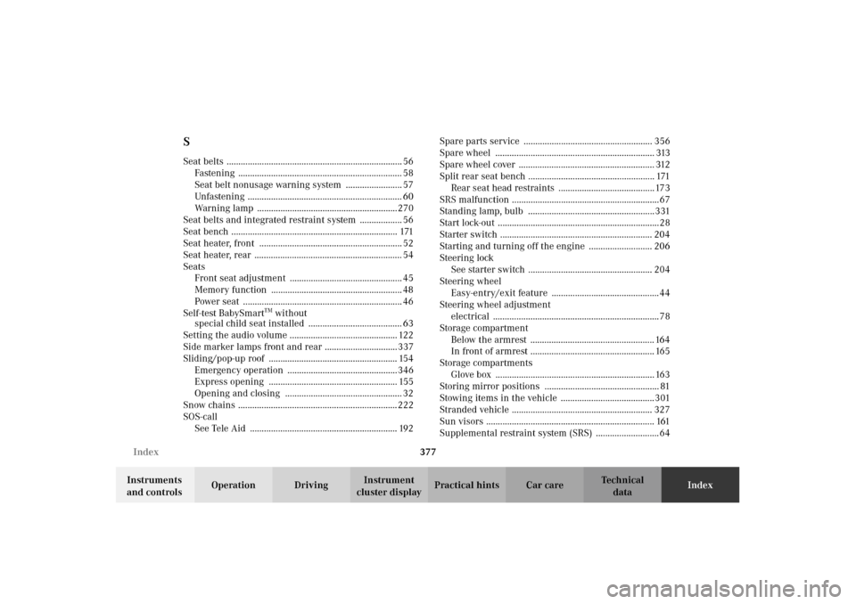
SSeat belts ........................................................................... 56
Fastening ...................................................................... 58
Seat belt nonusage warning system ........................ 57
Unfastening .................................................................. 60
Warning lamp ............................................................270
Seat belts and integrated restraint system .................. 56
Seat bench ....................................................................... 171
Seat heater, front ............................................................. 52
Seat heater, rear ............................................................... 54
Seats
Front seat adjustment ................................................ 45
Memory function ........................................................ 48
Power seat .................................................................... 46
Self-test BabySmart
TM without
special child seat installed ........................................ 63
Setting the audio volume .............................................. 122
Side marker lamps front and rear ............................... 337
Sliding/pop-up roof ....................................................... 154
Emergency operation ...............................................346
Express opening ....................................................... 155
Opening and closing .................................................. 32
Snow chains .................................................................... 222
SOS-call
See Tele Aid ............................................................... 192Spare parts service ....................................................... 356
Spare wheel .................................................................... 313
Spare wheel cover .......................................................... 312
Split rear seat bench ...................................................... 171
Rear seat head restraints ......................................... 173
SRS malfunction ...............................................................67
Standing lamp, bulb ......................................................331
Start lock-out .....................................................................28
Starter switch ................................................................. 204
Starting and turning off the engine ........................... 206
Steering lock
See starter switch ..................................................... 204
Steering wheel
Easy-entry/exit feature .............................................. 44
Steering wheel adjustment
electrical ....................................................................... 78
Storage compartment
Below the armrest ..................................................... 164
In front of armrest ..................................................... 165
Storage compartments
Glove box .................................................................... 163
Storing mirror positions ................................................. 81
Stowing items in the vehicle ........................................301
Stranded vehicle ............................................................ 327
Sun visors ........................................................................ 161
Supplemental restraint system (SRS) ........................... 64
J_G463.book Seite 377 Mittwoch, 19. September 2001 8:06 08