2002 MERCEDES-BENZ G500 spare tire
[x] Cancel search: spare tirePage 8 of 385

5 Contents
Practical hintsFirst aid kit, vehicle tools
and jack ......................................296
CD-changer .....................................296
Fuses ................................................297
Electrical outlet .............................. 301
Stowing items in the vehicle ........ 301
Hood .................................................302
Checking engine oil level .............304
Automatic transmission
fluid level ...................................305
Engine oil consumption ................305
Coolant level ...................................306
Adding coolant ...........................306
Windshield washer/headlamp
cleaning system .........................307
Windshield and headlamp
washer fluid mixing ratio .........307Vehicle jack .................................... 308
Wheels ............................................. 310
Tire replacement ........................ 310
Rotating wheels .......................... 311
Spare wheel cover ..........................312
Spare wheel ..................................... 313
Changing wheels ............................ 314
Tire inflation pressure .................. 318
Battery .............................................. 319
Jump starting ................................. 321
Towing the vehicle ........................ 324
Transmission selector lever,
manually unlocking .................. 327
Stranded vehicle ............................ 327
Exterior lamps ............................... 328
Headlamp assembly .................. 329
Fog lamp, front ........................... 332
Turn signal lamp, front ............ 334Turn signal lamp, side ...............335
Front and rear
side marker lamps .....................337
Taillamp assemblies ..................339
License plate lamp .....................340
Rear fog lamp / Backup lamp ... 341
Changing batteries in
the electronic key .....................343
Synchronizing
remote control ............................345
Emergency operation of
sliding/pop-up roof ...................346
Manual release for
fuel filler flap .............................347
Replacing wiper blades .................348
J_G463.book Seite 5 Mittwoch, 19. September 2001 8:06 08
Page 199 of 385
196 Tele Aid
Te ch n i c a l
data Instruments
and controlsOperationDrivingInstrument
cluster displayPractical hints Car care Index
Roadside Assistance button
Located below the center armrest cover is the Roadside
Assistance button. Pressing and holding the
button (for longer than 2 seconds) will initiate a call to a
Mercedes-Benz Roadside Assistance dispatcher. The
button will flash while the call is in progress. The
message “ROADSIDE ASSISTANCE – CONNECTING
CALL” will appear in the multifunction display. When
the connection is established, the message “ROADSIDE
ASSISTANCE – CALL CONNECTED” appears in the
multifunction display. The Tele Aid system will transmit
data generating the vehicle identification number,
model, color and location (subject to availability of
cellular and GPS signals).A voice connection between the Roadside Assistance
dispatcher and the occupants of the vehicle will be
established. When a voice connection is established the
audio system mutes and the message “TELE AID -
ROADSIDE ASSISTANCE CALL ACTIVE” appears in the
multifunction display. The nature of the need for
assistance can then be described. The Mercedes-Benz
Roadside assistance dispatcher will either dispatch a
qualified Mercedes-Benz technician or arrange to tow
your vehicle to the nearest Mercedes-Benz Center. For
ser vic es s uch as labor an d / or towing charges m ay ap ply.
Refer to the Roadside Assistance manual for more
information.
These programs are only available in the USA:
•S ign an d Drive s erv ices : Ser vices such as jump start,
a few gallons of fuel or the replacement of a flat tire
with the vehicle spare tire are obtainable,
•Remote Vehicle Diagnostics: This function permits
the Mercedes-Benz Roadside Assistance dispatcher
to download malfunction codes and actual vehicle
data.
Wa r n i n g !
If you feel at any way in jeopardy when in the
vehicle (e.g. smoke or fire in the vehicle, vehicle in
a dangerous road location), please do not wait for
voice contact after you have pressed the emergency
button. Carefully leave the vehicle and move to a
safe location. The Response Center will
automatically contact local emergency officials
with the vehicle’s approximate location if they
rec eive a n a utom at ic “SO S” si gna l a nd ca nn ot ma ke
voice contact with the vehicle occupants.
J_G463.book Seite 196 Mittwoch, 19. September 2001 8:06 08
Page 247 of 385
244 Driving systems
Te ch n i c a l
data Instruments
and controlsOperationDrivingInstrument
cluster displayPractical hints Car care Index
If the ESP warning lampv comes on continuously
and warning messages appears in the multifunction
display with the engine running, a malfunction has
been detected in either system. Only partial engine
output will be available.
If the BAS malfunctions, the brake system functions in
the usual manner, but without BAS, ESP and 4-ETS.
If the ESP warning lampv and the
Émalfunction indicator lamp come on and warning
messages appears in the multifunction display, have the
BAS or ESP checked at your authorized Mercedes-Benz
Light Truck Center as soon as possible.
With the ABS malfunctioning, the BAS, ESP and 4-ETS
are also switched off.
For warn in g m ess ages and malfun ction in d icator lamps ,
see page 264 and page 272.
Driving the vehicle with varied size tires will cause the
wheels to rotate at different speeds, therefore the ESP
may activate (yellow ESP warning lampv in
speedometer dial comes on). For this reason, all wheels,
including the spare wheel, must have the same tire
outside diameter.When testing the parking brake on a brake test
dynamometer, the engine must be shut off. Otherwise,
the ESP will immediately be engaged and will apply the
rear wheel brakes.
In winter operation, the maximum effectiveness of the
ESP is on ly achieved wit h Me rced es -B enz re comm end ed
M+S rated radial-ply tires and / or snow chains.
Synchronizing ESP
If the power supply was interrupted (battery
disconnected or empty), the ESP warning lampv
and warning messages appears in the multifunction
display with the engine running.
Turn steering wheel completely to the left and then to
the right. The ESP warning lampv and the warning
messages in the multifunction display should go out.
J_G463.book Seite 244 Mittwoch, 19. September 2001 8:06 08
Page 298 of 385
295 Contents - Practical hints
Te ch n i c a l
data Instruments
and controlsOperation DrivingInstrument
cluster displayPractical hintsCar care Index
Practical hintsFirst aid kit, vehicle tools
and jack ......................................296
CD-changer .....................................296
Fuses ................................................297
Electrical outlet .............................. 301
Stowing items in the vehicle ........ 301
Hood .................................................302
Checking engine oil level .............304
Automatic transmission
fluid level ...................................305
Engine oil consumption ................305
Coolant level ...................................306
Adding coolant ...........................306
Windshield washer/headlamp
cleaning system .........................307
Windshield and headlamp
washer fluid mixing ratio .........307Vehicle jack .................................... 308
Wheels ............................................. 310
Tire replacement ........................ 310
Rotating wheels .......................... 311
Spare wheel cover ..........................312
Spare wheel ..................................... 313
Changing wheels ............................ 314
Tire inflation pressure .................. 318
Battery .............................................. 319
Jump starting ................................. 321
Towing the vehicle ........................ 324
Transmission selector lever,
manually unlocking .................. 327
Stranded vehicle ............................ 327
Exterior lamps ............................... 328
Headlamp assembly .................. 329
Fog lamp, front ........................... 332
Turn signal lamp, front ............ 334Turn signal lamp, side ...............335
Front and rear
side marker lamps .....................337
Taillamp assemblies ..................339
License plate lamp .....................340
Rear fog lamp / Backup lamp ... 341
Changing batteries in
the electronic key .....................343
Synchronizing
remote control ............................345
Emergency operation of
sliding/pop-up roof ...................346
Manual release for
fuel filler flap .............................347
Replacing wiper blades .................348
J_G463.book Seite 295 Mittwoch, 19. September 2001 8:06 08
Page 315 of 385
312 Tires, Wheels
Te ch n i c a l
data Instruments
and controlsOperation DrivingInstrument
cluster displayPractical hintsCar care Index
Spare wheel cover
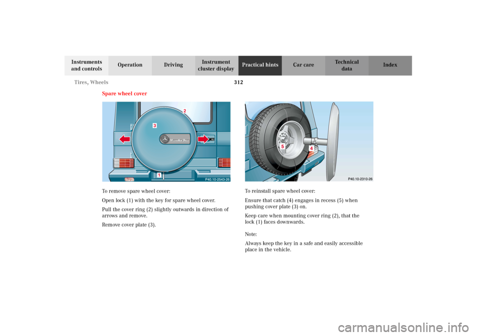
To remove spare wheel cover:
Open lock (1) with the key for spare wheel cover.
Pull the cover ring (2) slightly outwards in direction of
arrows and remove.
Remove cover plate (3).To reinstall spare wheel cover:
Ensure that catch (4) engages in recess (5) when
pushing cover plate (3) on.
Keep care when mounting cover ring (2), that the
lock (1) faces downwards.
Note:
Always keep the key in a safe and easily accessible
place in the vehicle.
3
2
1
J_G463.book Seite 312 Mittwoch, 19. September 2001 8:06 08
Page 316 of 385
313 Tires, Wheels
Te ch n i c a l
data Instruments
and controlsOperation DrivingInstrument
cluster displayPractical hintsCar care Index Spare wheel
Important!
The spare wheel rim is mounted with a full size tire of
the same type as on the vehicle, and is fully functional.
In the case of a flat tire, you may use the spare wheel.
For rim and tire specifications, refer to “Technical data”
on page 359.
Note:
Repair or replace damaged tire at your earliest
convenience.
To gain access to spare wheel, remove spare wheel
cover, see page 312.
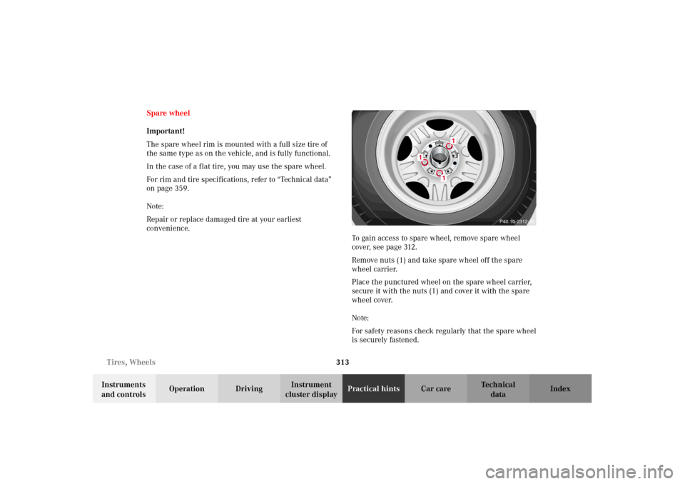
Remove nuts (1) and take spare wheel off the spare
wheel carrier.
Place the punctured wheel on the spare wheel carrier,
secure it with the nuts (1) and cover it with the spare
wheel cover.
Note:
For safety reasons check regularly that the spare wheel
is securely fastened.
P40.10-2312-26
1
1
1
J_G463.book Seite 313 Mittwoch, 19. September 2001 8:06 08
Page 319 of 385
316 Tires, Wheels
Te ch n i c a l
data Instruments
and controlsOperation DrivingInstrument
cluster displayPractical hintsCar care Index
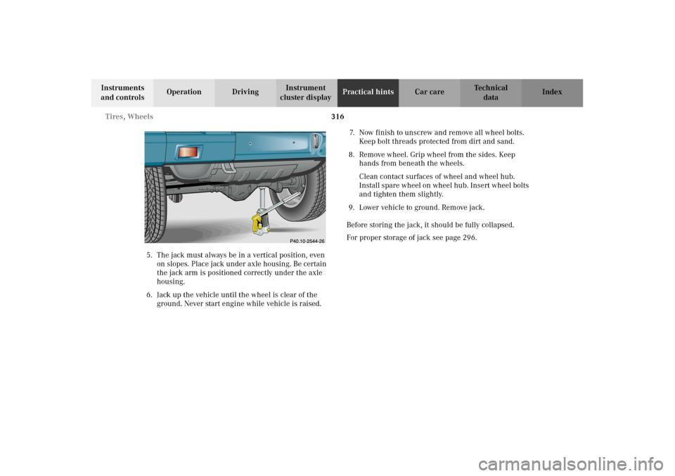
5. The jack must always be in a vertical position, even
on slopes. Place jack under axle housing. Be certain
the jack arm is positioned correctly under the axle
housing.
6. Jack up the vehicle until the wheel is clear of the
ground. Never start engine while vehicle is raised.7. Now finish to unscrew and remove all wheel bolts.
Keep bolt threads protected from dirt and sand.
8. Remove wheel. Grip wheel from the sides. Keep
hands from beneath the wheels.
Clean contact surfaces of wheel and wheel hub.
Install spare wheel on wheel hub. Insert wheel bolts
and tighten them slightly.
9. Lower vehicle to ground. Remove jack.
Before storing the jack, it should be fully collapsed.
For proper storage of jack see page 296.
J_G463.book Seite 316 Mittwoch, 19. September 2001 8:06 08
Page 321 of 385
318 Tires, Wheels
Te ch n i c a l
data Instruments
and controlsOperation DrivingInstrument
cluster displayPractical hintsCar care Index
Tire inflation pressure
A table (see fuel filler flap) lists the tire inflation
pressures specified for Mercedes-Benz recommended
tires as well as for the varying operating conditions.
Important!
Tire pressure changes by approximately 1.5 psi (0.1 bar)
per 18
°F (10
°C) of air temperature change. Keep this in
mind when checking tire pressure inside a garage –
especially in the winter.
Example:
If garage temperature = approximately +68
°F (+20
°C)
and ambient temperature = approximately +32
°F (0
°C)
then the adjusted air pressure = specified air pressure
+3 psi (+0.2 bar).Tire pressures listed for light loads are minimum values
offering high driving comfort. Increased inflation
pressures for heavy loads produce favorable handling
characteristics with lighter loads and are perfectly
permissible. The ride of the vehicle, however, will
become somewhat harder.
Tire temperature and pressure increase with the vehicle
speed. Tire pressure should therefore only be checked
and corrected on cold tires. Correct tire pressure in
warm tires only if pressure has dropped below the
pressure listed in the table and the respective operating
conditions are taken into consideration.
An underinflated tire due to a slow leak (e.g. due to a
nail in the tire) may cause damage such as tread
separation, bulging etc.. Regular tire pressure checks
(including the spare tire) at intervals of no more than
14 days are therefore essential.
J_G463.book Seite 318 Mittwoch, 19. September 2001 8:06 08