Page 227 of 350

224 Parking system
Technical
data Instruments
and controlsOperationDrivingInstrument
cluster displayPractical hints Car care Index
Parking assist (Parktronic)
(optional)
The Parktronic system assists the driver during parking
maneuvers. It visually and audibly indicates the
distance between the vehicle and an obstacle.
The front area of the vehicle is monitored when driving
forward. When reversing, the front as well as the rear
areas are monitored.
With the electronic key in steering lock position 2,
Parktronic engages automatically at speeds up to
approximately 10 mph (15 km / h) and deactivates
during higher speeds.
Parktronic can be switched off by a control switch
located in the center console. It engages automatically
again when starting the engine.
See page 228 for parktronic switch.
Wa r n i n g !
Parktronic is a supplemental system. It is not
intended to nor does it replace the need for extreme
care. The responsibility during parking and other
critical maneuvers rests always with the driver.Special attention must be paid to objects having
smooth surfaces or low silhouettes (e.g. trailer
couplings, painted posts, or street curbs). Such
objects may not be detected by the system and can
damage the vehicle.The operational function of the Parktronic can be
affected by dirty sensors, especially at times of
snow and ice. See page 307 for notes on cleaning
the parktronic system sensors.Interference caused by other ultrasonic signals
(e.g. working jackhammers or the air brakes of
trucks) can cause the system to send erratic
indications, and should be taken into
consideration.
W210.book Seite 224 Mittwoch, 30. Mai 2001 11:45 11
Page 236 of 350

233 Contents – Instrument cluster display
Technical
data Instruments
and controlsOperation DrivingInstrument
cluster displayPractical hints Car care Index
Instrument cluster displayMalfunction and indicator lamps
in the instrument cluster .........234
On-board diagnostic system .....234
Check engine malfunction
indicator lamp .............................234
Brake warning lamp ..................235
Supplemental restraint system
(SRS) indicator lamp ..................236
Fuel reserve and fuel cap
placement warning ....................236
Electronic stability program
(ESP) — warning lamp ...............237
BAS / ESP malfunction
indicator lamp .............................237ABS malfunction
indicator lamp ............................ 238
Seat belt warning lamp ............. 238
Malfunction and indicator lamp
in the center console ............... 239
AIRBAG OFF
indicator lamp ............................ 239
Malfunction and warning
messages in the
multifunction display .............. 240
DISPLAY DEFECTIVE ................ 241
BATTERY / ALTERNATOR ........ 242
ABS-SYSTEM .............................. 243
BRAKE ASSIST ........................... 243
BRAKE LINING WEAR .............. 244BRAKE FLUID .............................244
PARKING BRAKE .......................245
ENGINE FAN ...............................245
COOLANT (coolant level) ..........246
COOLANT TEMP. ........................247
LIGHTING SYSTEM ....................248
LIGHT SENSOR ...........................249
REMOVE KEY .............................249
STEERING GEAR OIL .................250
ENGINE OIL LEVEL ................... 251
WASHER FLUID .........................252
ELEC. STABIL. PROG.
(Electronic stability program) ..253
TELE AID .....................................253
W210.book Seite 233 Mittwoch, 30. Mai 2001 11:45 11
Page 238 of 350

235 Malfunction and indicator lamps
Technical
data Instruments
and controlsOperation DrivingInstrument
cluster displayPractical hints Car care Index An on-board diagnostic connector is located in the
passenger compartment near to the parking brake
pedal, allowing the accurate identification of system
malfunctions through the readout of diagnostic trouble
codes.
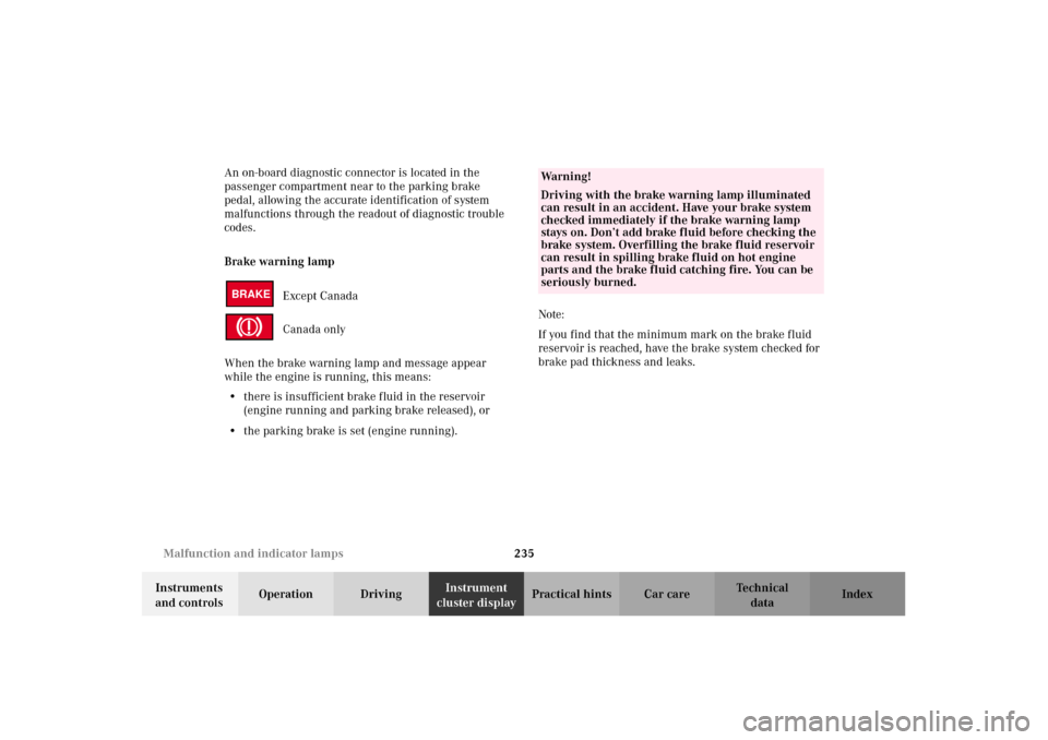
Brake warning lamp
Except Canada
Canada only
When the brake warning lamp and message appear
while the engine is running, this means:
•there is insufficient brake fluid in the reservoir
(engine running and parking brake released), or
•the parking brake is set (engine running).Note:
If you find that the minimum mark on the brake fluid
reservoir is reached, have the brake system checked for
brake pad thickness and leaks.
BRAKE
Wa r n i n g !
Driving with the brake warning lamp illuminated
can result in an accident. Have your brake system
checked immediately if the brake warning lamp
stays on. Don’t add brake fluid before checking the
brake system. Overfilling the brake fluid reservoir
can result in spilling brake fluid on hot engine
parts and the brake fluid catching fire. You can be
seriously burned.
W210.book Seite 235 Mittwoch, 30. Mai 2001 11:45 11
Page 248 of 350
245 Malfunction and warning messages
Technical
data Instruments
and controlsOperation DrivingInstrument
cluster displayPractical hints Car care Index PA R K I N G B R A K E
Parking brake, see page 202.ENGINE FAN
1 The cooling fan for the coolant is faulty.
Observe the coolant temperature gauge while driving, see page 90. Line 1 Line 2
PARKING BRAKE RELEASE BRAKE!Line 1 Line 2
ENGINE FAN VISIT WORKSHOP!
1
W210.book Seite 245 Mittwoch, 30. Mai 2001 11:45 11
Page 251 of 350
248 Malfunction and warning messages
Technical
data Instruments
and controlsOperation DrivingInstrument
cluster displayPractical hints Car care Index
LIGHTING SYSTEMWhen the message appears after starting the engine, or
if it come on while driving, this indicates a failure in the
parking lamp, taillamp, stop lamp, or low beam
headlamp. See page 288 for instructions on replacing
bulbs.
If an exterior lamp fails, the message will appear only
when that lamp is switched on.
If a brake lamp fails, the message will appear when
applying the brake and stays on until the engine is
turned off.
Note:
If additional lighting is installed (e.g. auxiliary
headlamps etc.) be certain to connect into the fuse
before the failure indicator monitoring unit order to
avoid damaging the system.
Line 1 Line 2
LAMP DEFECTIVE CHECK LAMPS!
DISPLAY DEFECTIVE VISIT WORKSHOP!
W210.book Seite 248 Mittwoch, 30. Mai 2001 11:45 11
Page 270 of 350

267 Vehicle jack
Technical
data Instruments
and controlsOperation DrivingInstrument
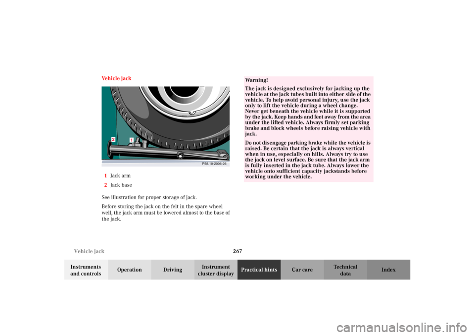
cluster displayPractical hintsCar care Index Ve h i c l e j a c k
1Jack arm
2Jack base
See illustration for proper storage of jack.
Before storing the jack on the felt in the spare wheel
well, the jack arm must be lowered almost to the base of
the jack.
P58.10-2006-26
2
1
Wa r n i n g !
The jack is designed exclusively for jacking up the
vehicle at the jack tubes built into either side of the
vehicle. To help avoid personal injury, use the jack
only to lift the vehicle during a wheel change.
Never get beneath the vehicle while it is supported
by the ja ck. Keep ha nd s an d feet away from the area
under the lifted vehicle. Always firmly set parking
brake and block wheels before raising vehicle with
jack.Do not d i sen ga ge park in g b ra ke whi l e the vehic l e is
raised. Be certain that the jack is always vertical
when in use, especially on hills. Always try to use
the jack on level surface. Be sure that the jack arm
is fully inserted in the jack tube. Always lower the
vehicle onto sufficient capacity jackstands before
working under the vehicle.
W210.book Seite 267 Mittwoch, 30. Mai 2001 11:45 11
Page 276 of 350

273 Tires, Wheels
Technical
data Instruments
and controlsOperation DrivingInstrument
cluster displayPractical hintsCar care Index Changing wheelsMove vehicle to a level area which is a safe distance
from the roadway.
1. Set parking brake and turn on hazard warning
flasher.
2. Move selector lever to position “P” and turn off
engine.
3. Prevent vehicle from rolling away by blocking
wheels with wheel chocks (not supplied with
vehicle) or sizable wood block or stone. When
changing a wheel on a hill, place chocks on the
downhill side blocking both wheels of the other
axle. On a level road, place one chock in front of and
one behind the wheel that is diagonally opposite to
the wheel being changed.
Wa r n i n g !
The jack is designed exclusively for jacking up the
vehicle at the jack tubes built into either side of the
vehicle. To help avoid personal injury, use the jack
only to lift the vehicle during a wheel change.
Never get beneath the vehicle while it is supported
by t he j ack . Keep han ds a nd feet away from t he a rea
under the lifted vehicle. Always firmly set parking
brake and block wheels before raising vehicle with
jack.Do n ot d is engage parki n g brake w hil e t he vehi c le i s
raised. Be certain that the jack is always vertical
when in use, especially on hills. Always try to use
the jack on level surface. Be sure that the jack arm
is fully inserted in the jack tube. Always lower the
vehicle onto sufficient capacity jackstands before
working under the vehicle.
W210.book Seite 273 Mittwoch, 30. Mai 2001 11:45 11
Page 286 of 350

283 Jump starting
Technical
data Instruments
and controlsOperation DrivingInstrument
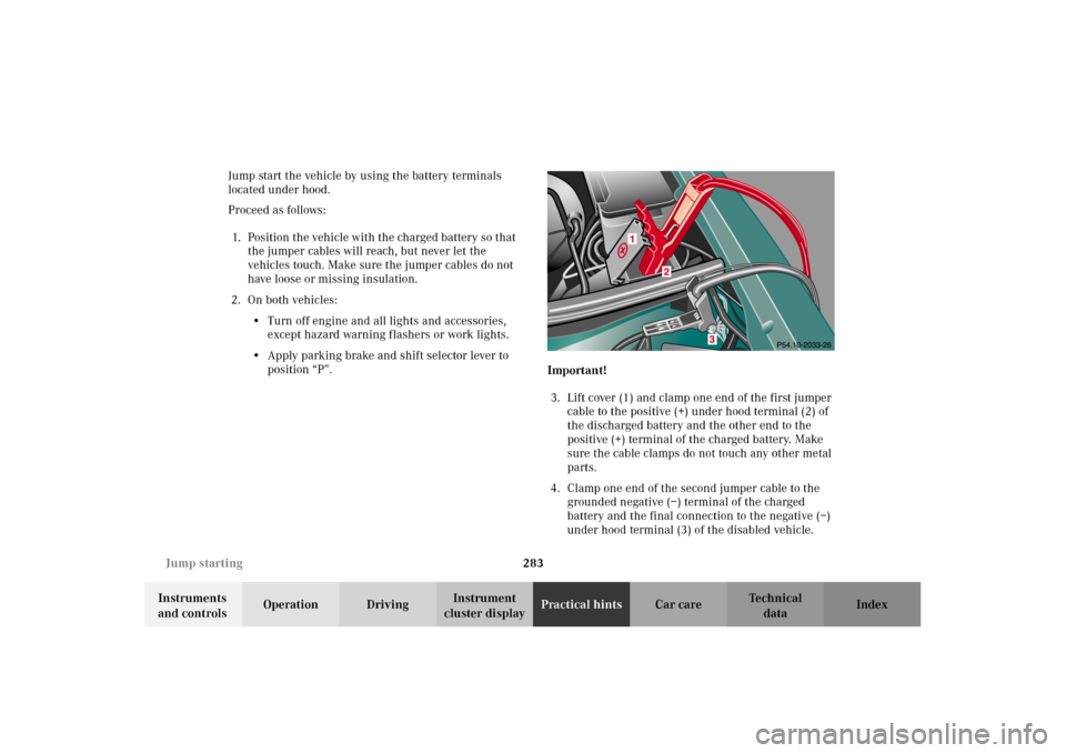
cluster displayPractical hintsCar care Index Jump start the vehicle by using the battery terminals
located under hood.
Proceed as follows:
1. Position the vehicle with the charged battery so that
the jumper cables will reach, but never let the
vehicles touch. Make sure the jumper cables do not
have loose or missing insulation.
2. On both vehicles:
•Turn off engine and all lights and accessories,
except hazard warning flashers or work lights.
•Apply parking brake and shift selector lever to
position “P”.
Important!
3. Lift cover (1) and clamp one end of the first jumper
cable to the positive (+) under hood terminal (2) of
the discharged battery and the other end to the
positive (+) terminal of the charged battery. Make
sure the cable clamps do not touch any other metal
parts.
4. Clamp one end of the second jumper cable to the
grounded negative (–) terminal of the charged
battery and the final connection to the negative (–)
under hood terminal (3) of the disabled vehicle.
W210.book Seite 283 Mittwoch, 30. Mai 2001 11:45 11