Page 241 of 350

238 Malfunction and indicator lamps
Technical
data Instruments
and controlsOperation DrivingInstrument
cluster displayPractical hints Car care Index
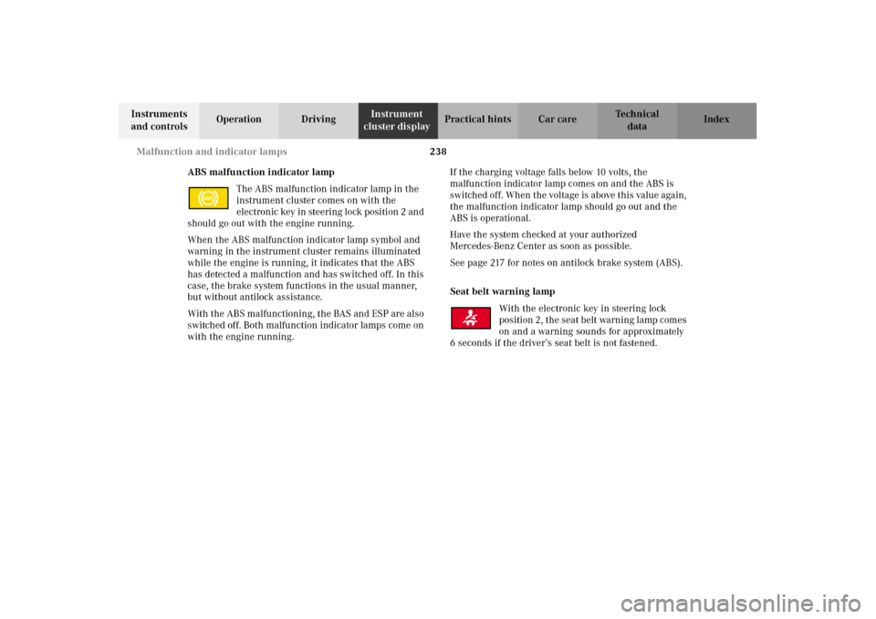
ABS malfunction indicator lamp
The ABS malfunction indicator lamp in the
instrument cluster comes on with the
electron ic key in ste eri ng lock posi ti on 2 an d
should go out with the engine running.
When the ABS malfunction indicator lamp symbol and
warning in the instrument cluster remains illuminated
while the engine is running, it indicates that the ABS
has detected a malfunction and has switched off. In this
case, the brake system functions in the usual manner,
but without antilock assistance.
With the ABS malfunctioning, the BAS and ESP are also
switched off. Both malfunction indicator lamps come on
with the engine running.If the charging voltage falls below 10 volts, the
malfunction indicator lamp comes on and the ABS is
switched of f. When the voltage is above this value again,
the malfunction indicator lamp should go out and the
ABS is operational.
Have the system checked at your authorized
Mercedes-Benz Center as soon as possible.
See page 217 for notes on antilock brake system (ABS).
Seat belt warning lamp
With the electronic key in steering lock
position 2, the seat belt warning lamp comes
on and a warning sounds for approximately
6 seconds if the driver’s seat belt is not fastened.
ABS
W210.book Seite 238 Mittwoch, 30. Mai 2001 11:45 11
Page 242 of 350

239 Malfunction and indicator lamps
Technical
data Instruments
and controlsOperation DrivingInstrument
cluster displayPractical hints Car care Index Malfunction and indicator lamp in the center
console
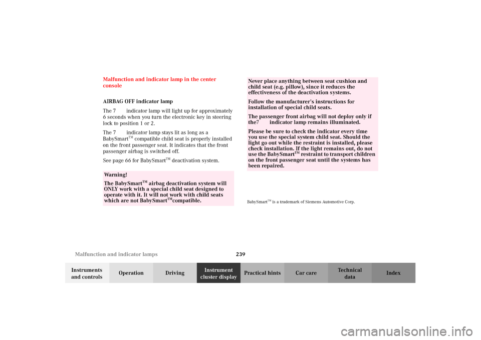
AIRBAG OFF indicator lamp
The 7 indicator lamp will light up for approximately
6 seconds when you turn the electronic key in steering
lock to position 1 or 2.
The 7 indicator lamp stays lit as long as a
BabySmart
TM compatible child seat is properly installed
on the front passenger seat. It indicates that the front
passenger airbag is switched off.
See page 66 for BabySmart
TM deactivation system.
BabySmart
TM is a trademark of Siemens Automotive Corp.
Wa r n i n g !
The BabySmart
TM airbag deactivation system will
ONLY work with a special child seat designed to
operate with it. It will not work with child seats
which are not BabySmart
TMcompatible.
Never place anything between seat cushion and
child seat (e.g. pillow), since it reduces the
effectiveness of the deactivation systems.Follow the manufacturer’s instructions for
installation of special child seats.The passenger front airbag will not deploy only if
the7 indicator lamp remains illuminated.Please be sure to check the indicator every time
you use the special system child seat. Should the
light go out while the restraint is installed, please
check installation. If the light remains out, do not
use the BabySmart
TM restraint to transport children
on the front passenger seat until the systems has
been repaired.
W210.book Seite 239 Mittwoch, 30. Mai 2001 11:45 11
Page 258 of 350

255 Contents – Practical hints
Technical
data Instruments
and controlsOperation DrivingInstrument
cluster displayPractical hintsCar care Index
Practical hintsFirst aid kit .....................................256
Stowing things in the vehicle ......256
Fuses ................................................257
Hood .................................................259
Checking engine oil level .............262
Automatic transmission
fluid level ...................................263
Coolant level ...................................263
Adding coolant ...........................264
Windshield and headlamp
washer system ...........................265
Windshield and headlamp
washer fluid mixing ratio .........265
Spare wheel, vehicle tools,
storage compartment ................266Vehicle jack .................................... 267
Wheels ............................................ 268
Tire replacement ....................... 268
Rotating wheels ......................... 269
Spare wheel .................................... 270
Spare wheel bolts ...................... 270
Spare wheel .....................................271
Changing wheels ........................... 273
Tire inflation pressure ................. 278
Battery ............................................. 280
Jump starting ................................. 282
Towing the vehicle ........................ 285
Transmission selector lever,
manually unlocking ................. 287Exterior lamps ................................288
Headlamp assembly ...................289
Taillamp assemblies ..................292
Changing batteries
in the electronic main key ......294
Synchronizing
remote control ............................296
Emergency engine shut-down .....296
Rear seat cushion ..........................297
Emergency operation of
sliding / pop-up roof .................298
Manual release for
fuel filler flap .............................299
Replacing wiper blade insert .......300
Roof rack .........................................302
W210.book Seite 255 Mittwoch, 30. Mai 2001 11:45 11
Page 259 of 350
256 First aid kit
Technical
data Instruments
and controlsOperation DrivingInstrument
cluster displayPractical hintsCar care Index
First aid kit
The first aid kit is located in the rear bench armrest.
To o pen :
Press button (1) and pull drawer out to its final stop.
Remove the first aid kit.Stowing things in the vehicle
1
P91.27-2004-26
Wa r n i n g !
To help avoid personal injury during a collision or
sudden maneuver, exercise care when stowing
things. Put luggage or cargo in the trunk if
possible. Do not pile luggage or cargo higher than
the seat backs. Do not place anything on the shelf
below the rear window.
W210.book Seite 256 Mittwoch, 30. Mai 2001 11:45 11
Page 261 of 350
258 Fuses
Technical
data Instruments
and controlsOperation DrivingInstrument
cluster displayPractical hintsCar care Index
2Auxiliary fuse box below rear seat bench
To gain access, remove rear seat bench.
See page 297.3Auxiliary fuse box to left of exterior lamp switch
To again access, open door, pry off cover and
remove.
W210.book Seite 258 Mittwoch, 30. Mai 2001 11:45 11
Page 283 of 350

280 Battery
Technical
data Instruments
and controlsOperation DrivingInstrument
cluster displayPractical hintsCar care Index
Battery
Important!
Battery replacement information:
The maintenance-free battery is located under the rear
seat cushion. To minimize the chance for acid leakage
which could cause severe burns during a crash or
rollover, a special acid leakage resistant battery was
factory installed. A replacement battery for the vehicle must not leak acid when upside down for at least 15
minutes. Your authorized Mercedes-Benz Center can
provide such a special battery.
The service life of the battery is dependent on its
condition of charge. The battery should always be kept
sufficiently charged, in order to last an optimum length
of time.
Therefore, we strongly recommend that you have the
battery charge checked frequently, and corrected if
necessary, especially if you use the vehicle less than
approximately 200 miles (300 km) per month,
mostly for short distance trips, or if it is not used for
long periods of time.
Only charge a battery with a battery charger after the
battery has been disconnected from the vehicle’s
electrical circuit.
Always disconnect the battery negative lead first and
connect last.
When removing and connecting the battery, always
make sure that all electrical consumers are off and the
electronic key is in steering lock position 0. The battery,
its filler caps, the vent tube and the opposite plug must
always be securely installed when the vehicle in
Wa r n i n g !
Failure to follow these instructions can result in
severe injury or death.Never lean over batteries while connecting, you
might get injured.Battery fluid contains sulfuric acid. Do not allow
this fluid to come in contact with eyes, skin or
clothing. In case it does, immediately flush affected
area with water and seek medical help if necessary.A battery will also produce hydrogen gas, which is
flammable and explosive. Keep flames or sparks
away from battery, avoid improper connection of
jumper cables, smoking etc..
W210.book Seite 280 Mittwoch, 30. Mai 2001 11:45 11
Page 284 of 350

281 Battery
Technical
data Instruments
and controlsOperation DrivingInstrument
cluster displayPractical hintsCar care Index operation. During removal and installation always
protect the disconnected battery positive (+) terminal
with the cover attached to the battery.
While the engine is running the battery terminal clamps
must not be loosened or detached, otherwise the
generator and other electronic components would be
damaged.
Note:
The selector lever will remain locked in position “P” and
the electronic key cannot be turned in the steering lock,
if the vehicle battery is disconnected or discharged.
After reconnecting the battery also resynchronize the
front seat head restraints, the express feature of the
power windows, and the electronic stability program
(ESP), see pages 47, 156 and 221.Battery recycling
Batteries contain material that can harm the
environment with improper disposal.
Large 12 Volt storage batteries contain lead.
Recycling of batteries is the preferred method of
disposal.
Many states require sellers of batteries to accept old
batteries for recycling.
W210.book Seite 281 Mittwoch, 30. Mai 2001 11:45 11
Page 293 of 350

290 Exterior lamps
Technical
data Instruments
and controlsOperation DrivingInstrument
cluster displayPractical hintsCar care Index
Bulbs for high and low beam
H7 (55 W)
Open hood.
Twist cover (1 or 2) counterclockwise and remove.
Pull off electrical connector (4) or (5).
Twist bulb holder counterclockwise and remove bulb
from it.
Insert the new bulb so that its base fits in recess of the
holder.
Install bulb holder and twist clockwise to its stop, and
reinstall electrical connector.
Reinstall cover (1 or 2), twist it clockwise until seated
securely.
Xenon (optional)
Bulb for low beamBulbs for high beam
H7 (55 W)
Open hood.
Twist cover (2) counterclockwise and remove.
Pull off electrical connector.
Twist bulb holder counterclockwise and remove bulb
from it.
Insert the new bulb so that its base fits in recess of the
holder.
Install bulb holder and twist clockwise to its stop, and
reinstall electrical connector.Ensure that base is
secured on both sides (arrows)
Reinstall cover (2), twist it clockwise until seated
securely.
Wa r n i n g !
Because of high voltage in Xenon lamps, it is
dangerous to replace the bulb or repair the lamp
and its components. We recommend that you have
such work done by a qualified technician.
W210.book Seite 290 Mittwoch, 30. Mai 2001 11:45 11