Page 227 of 350

224 Parking system
Technical
data Instruments
and controlsOperationDrivingInstrument
cluster displayPractical hints Car care Index
Parking assist (Parktronic)
(optional)
The Parktronic system assists the driver during parking
maneuvers. It visually and audibly indicates the
distance between the vehicle and an obstacle.
The front area of the vehicle is monitored when driving
forward. When reversing, the front as well as the rear
areas are monitored.
With the electronic key in steering lock position 2,
Parktronic engages automatically at speeds up to
approximately 10 mph (15 km / h) and deactivates
during higher speeds.
Parktronic can be switched off by a control switch
located in the center console. It engages automatically
again when starting the engine.
See page 228 for parktronic switch.
Wa r n i n g !
Parktronic is a supplemental system. It is not
intended to nor does it replace the need for extreme
care. The responsibility during parking and other
critical maneuvers rests always with the driver.Special attention must be paid to objects having
smooth surfaces or low silhouettes (e.g. trailer
couplings, painted posts, or street curbs). Such
objects may not be detected by the system and can
damage the vehicle.The operational function of the Parktronic can be
affected by dirty sensors, especially at times of
snow and ice. See page 307 for notes on cleaning
the parktronic system sensors.Interference caused by other ultrasonic signals
(e.g. working jackhammers or the air brakes of
trucks) can cause the system to send erratic
indications, and should be taken into
consideration.
W210.book Seite 224 Mittwoch, 30. Mai 2001 11:45 11
Page 228 of 350
225 Parking system
Technical
data Instruments
and controlsOperationDrivingInstrument
cluster displayPractical hints Car care Index Sensors
1Sensors located in bumper
(front bumper shown)A total of 10 sensors (1) monitor the vehicle’s front and
rear areas. Six sensors are located in the front bumper,
four sensors in the rear bumper.
For proper operation of the Parktronic always keep the
sensors clean, especially at times of snow and ice.
See page 307 for instructions on cleaning the sensors in
the bumpers.
P88.20-2049-261
1
1
W210.book Seite 225 Mittwoch, 30. Mai 2001 11:45 11
Page 236 of 350

233 Contents – Instrument cluster display
Technical
data Instruments
and controlsOperation DrivingInstrument
cluster displayPractical hints Car care Index
Instrument cluster displayMalfunction and indicator lamps
in the instrument cluster .........234
On-board diagnostic system .....234
Check engine malfunction
indicator lamp .............................234
Brake warning lamp ..................235
Supplemental restraint system
(SRS) indicator lamp ..................236
Fuel reserve and fuel cap
placement warning ....................236
Electronic stability program
(ESP) — warning lamp ...............237
BAS / ESP malfunction
indicator lamp .............................237ABS malfunction
indicator lamp ............................ 238
Seat belt warning lamp ............. 238
Malfunction and indicator lamp
in the center console ............... 239
AIRBAG OFF
indicator lamp ............................ 239
Malfunction and warning
messages in the
multifunction display .............. 240
DISPLAY DEFECTIVE ................ 241
BATTERY / ALTERNATOR ........ 242
ABS-SYSTEM .............................. 243
BRAKE ASSIST ........................... 243
BRAKE LINING WEAR .............. 244BRAKE FLUID .............................244
PARKING BRAKE .......................245
ENGINE FAN ...............................245
COOLANT (coolant level) ..........246
COOLANT TEMP. ........................247
LIGHTING SYSTEM ....................248
LIGHT SENSOR ...........................249
REMOVE KEY .............................249
STEERING GEAR OIL .................250
ENGINE OIL LEVEL ................... 251
WASHER FLUID .........................252
ELEC. STABIL. PROG.
(Electronic stability program) ..253
TELE AID .....................................253
W210.book Seite 233 Mittwoch, 30. Mai 2001 11:45 11
Page 240 of 350

237 Malfunction and indicator lamps
Technical
data Instruments
and controlsOperation DrivingInstrument
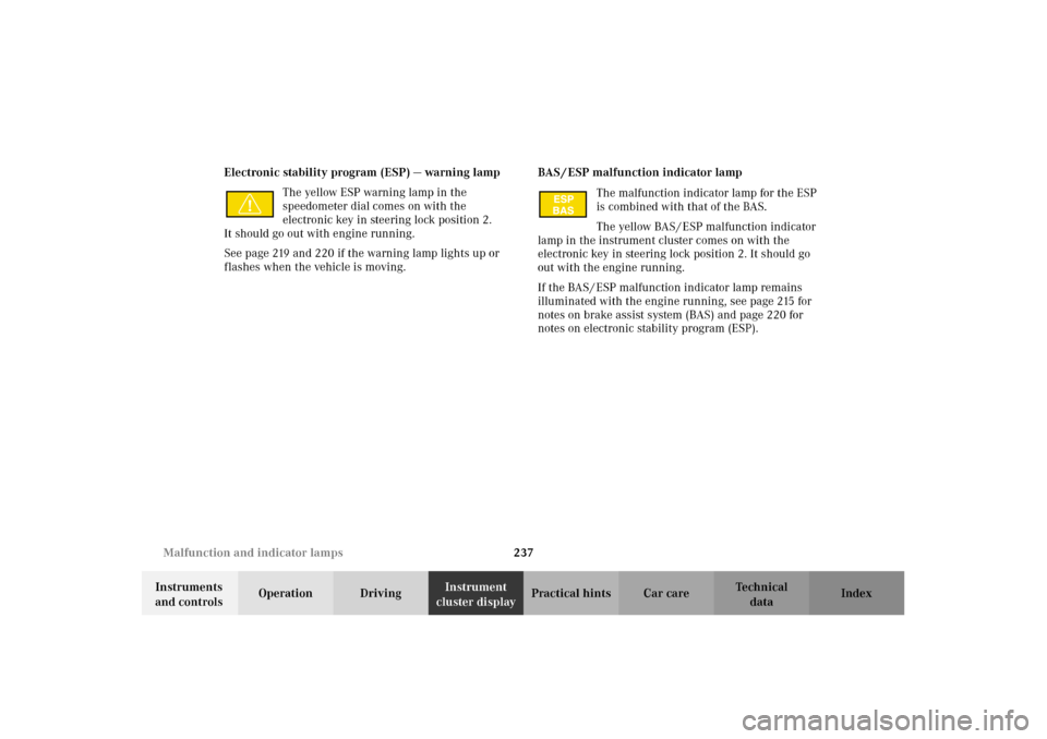
cluster displayPractical hints Car care Index Electronic stability program (ESP) — warning lamp
The yellow ESP warning lamp in the
speedometer dial comes on with the
electronic key in steering lock position 2.
It should go out with engine running.
See page 219 and 220 if the warning lamp lights up or
flashes when the vehicle is moving.BAS / ESP malfunction indicator lamp
The malfunction indicator lamp for the ESP
is combined with that of the BAS.
The yellow BAS / ESP malfunction indicator
lamp in the instrument cluster comes on with the
electronic key in steering lock position 2. It should go
out with the engine running.
If the BAS / ESP malfunction indicator lamp remains
illuminated with the engine running, see page 215 for
notes on brake assist system (BAS) and page 220 for
notes on electronic stability program (ESP).
W210.book Seite 237 Mittwoch, 30. Mai 2001 11:45 11
Page 241 of 350

238 Malfunction and indicator lamps
Technical
data Instruments
and controlsOperation DrivingInstrument
cluster displayPractical hints Car care Index
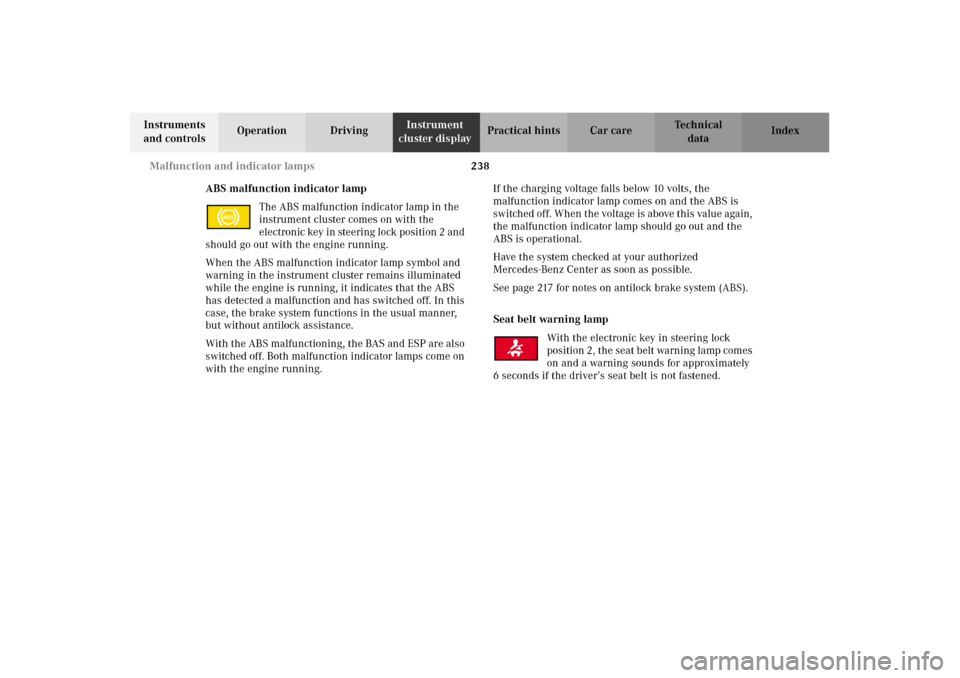
ABS malfunction indicator lamp
The ABS malfunction indicator lamp in the
instrument cluster comes on with the
electron ic key in ste eri ng lock posi ti on 2 an d
should go out with the engine running.
When the ABS malfunction indicator lamp symbol and
warning in the instrument cluster remains illuminated
while the engine is running, it indicates that the ABS
has detected a malfunction and has switched off. In this
case, the brake system functions in the usual manner,
but without antilock assistance.
With the ABS malfunctioning, the BAS and ESP are also
switched off. Both malfunction indicator lamps come on
with the engine running.If the charging voltage falls below 10 volts, the
malfunction indicator lamp comes on and the ABS is
switched of f. When the voltage is above this value again,
the malfunction indicator lamp should go out and the
ABS is operational.
Have the system checked at your authorized
Mercedes-Benz Center as soon as possible.
See page 217 for notes on antilock brake system (ABS).
Seat belt warning lamp
With the electronic key in steering lock
position 2, the seat belt warning lamp comes
on and a warning sounds for approximately
6 seconds if the driver’s seat belt is not fastened.
ABS
W210.book Seite 238 Mittwoch, 30. Mai 2001 11:45 11
Page 246 of 350
243 Malfunction and warning messages
Technical
data Instruments
and controlsOperation DrivingInstrument
cluster displayPractical hints Car care Index ABS-SYSTEM
A malfunction has been detected in the system. The
brake system functions in the usual manner, but
without antilock assistance.
With the ABS malfunctioning, the BAS and ESP are also
switched off.
Have the system checked at your authorized
Mercedes-Benz Center as soon as possible.BRAKE ASSIST
A malfunction has been detected in the system. The
brake system functions in the usual manner, but
without BAS.
Line 1 Line 2
ABS-SYSTEM VISIT WORKSHOP!
P54.30-2938-21
Line 1 Line 2
BRAKE ASSIST VISIT WORKSHOP!
DISPLAY DEFECTIVE VISIT WORKSHOP!
W210.book Seite 243 Mittwoch, 30. Mai 2001 11:45 11
Page 256 of 350

253 Malfunction and warning messages
Technical
data Instruments
and controlsOperation DrivingInstrument
cluster displayPractical hints Car care Index ELEC. STABIL. PROG.
(Electronic stability program)
1 A malfunction has been detected in the system. Pressing the
accelerator pedal will require greater effort. Only partial engine
output will be available.
2 This message may be displayed if the power supply was
interrupted (battery disconnected or empty).
3 Synchronize ESP. See page 221.
TELE AID1 The Tele Aid system consists of three types of response; automatic
and manual emergency, roadside assistance and information. With
this message displayed, one or more functions may not be
avai lable.
See page 178 for notes on the Tele Aid.If a malfunction is indicated as outlined above, have the
system checked at the nearest Mercedes-Benz Center as
soon as possible.
Line 1 Line 2
DISPLAY DEFECTIVE VISIT WORKSHOP!
ELEC. STABIL. PROG. VISIT WORKSHOP!
1, 2, 3
Line 1 Line 2
TELE AID VISIT WORKSHOP!
W210.book Seite 253 Mittwoch, 30. Mai 2001 11:45 11
Page 260 of 350
257 Fuses
Technical
data Instruments
and controlsOperation DrivingInstrument
cluster displayPractical hintsCar care Index Fuses
Before replacing a blown fuse, determine the cause of
the short circuit.
Spare fuses are supplied inside the main fuse box.
Observe amperage and color of fuse.
A special fuse puller is supplied with the vehicle tools.
Always use a new fuse for replacement. Never attempt to
repair or bridge a blown fuse.
A fuse chart can be found inside the corresponding fuse
box cover.
1Main fuses box in engine compartment
To gain access to the main fuse box (1), release
clamp (arrow), lift the fuse box cover up and remove it.
To close the main fuse box, engage right end of cover
and secure with clamp.
P54.15-2068-26
1
W210.book Seite 257 Mittwoch, 30. Mai 2001 11:45 11