2002 MERCEDES-BENZ CLK430 torque
[x] Cancel search: torquePage 201 of 330

198 Automatic transmission
Technical
data Instruments
and controlsOperationDrivingInstrument
cluster displayPractical hints Car care Index
Press and hold selector lever in the æ direction:
The transmission will shift from the current gear
directly to gear range “D”.
Important!
With transmission in gear range “D”, “4” or “3”,
upshifting from 1st to 2nd to 3rd gear is delayed
depending on vehicle speed and engine temperature.
This allows the catalytic converter to heat up more
quickly to operating temperatures.During the brief warm-up period this delayed upshift
and increased engine noise might be perceived as a
malfunction. However, neither the engine nor
transmission are negatively affected by this mode of
operation.
The delayed upshift is effective with vehicle speeds
below 31 mph (50 km/h) at partial throttle and engine
temperatures below 95
°F (35
°C).
To avoid overrevving the engine when the selector lever
is m ove d to a lower gear range , t he tran smi ss ion will n ot
shift to a lower gear, if the engine’s revolutions per
minute limit would be exceeded. In this case there will
be no downshift, even when the vehicle speed reaches
the engine’s RPM limit of that gear, e.g. by applying the
service brakes.
To prevent the engine from laboring at low RPM when
driving uphill gradients or with your vehicle heavily
loaded, the automatic transmission will downshift when
necessary to maintain engine RPM within the best
torque range.
Wa r n i n g !
O n s l i p p e ry ro a d s u rfa c es , n eve r d ow n s h i f t i n o rd e r
to obtain braking action. This could result in drive
wheel slip and reduced vehicle control. Your
vehicle’s ABS will not prevent this type of loss of
control.
J_C208_II.book Seite 198 Donnerstag, 31. Mai 2001 10:13 10
Page 221 of 330

218 Driving systems
Technical
data Instruments
and controlsOperationDrivingInstrument
cluster displayPractical hints Car care Index
Electronic stability program (ESP)
The ESP enhances directional control and reduces
driving wheel spin of the vehicle under various driving
conditions.
Over/understeering of the vehicle is counteracted by
applying brakes to the appropriate wheel to create a
countervailing vehicle movement. Engine torque is also
limited. The ESP warning lamp, located in the
speedometer dial, starts to flash when ESP is in
operation.Important!
If the ESP warning lampv flashes:
•During take-off apply as little throttle as possible.
•While driving ease up on the accelerator.
•Adapt your speed and driving to the prevailing road
conditions.
•Do not switch off the ESP.
Caution!
If the vehicle is towed with the front axle raised (see
towing the vehicle on page 272), the engine must be
shut off (electronic key in steering lock position 0 or 1).
Otherwise, the ESP will immediately be engaged and
will apply the rear wheel brakes.
Wa r n i n g !
ESP cannot prevent the natural laws of physics
from acting on the vehicle, nor can it increase the
traction afforded. The ESP cannot prevent
ac c id ent s, i nc l udi ng t hose resul tin g from exc es si ve
speed in turns, or aquaplaning. Only a safe,
attentive, and skillful driver can prevent accidents.
The capabilities of an ESP equipped vehicle must
never be exploited in a reckless or dangerous
manner which could jeopardize the user’s safety or
the safety of others.
J_C208_II.book Seite 218 Donnerstag, 31. Mai 2001 10:13 10
Page 223 of 330

220 Driving systems
Technical
data Instruments
and controlsOperationDrivingInstrument
cluster displayPractical hints Car care Index
ESP control switch
ESP control switch located on center console.
To switch ESP off, press upper half of the switch.
ESP warning lampv, located in speedometer dial,
comes on.
To switch ESP on again, press lower half of the switch.
ESP warning lampv, located in speedometer dial,
goes out.To improve the vehicle’s traction when driving with
sn ow chain s, or startin g of f in d eep sn ow, san d o r grave l,
switch off ESP by pressing the upper half of the ESP
switch. The ESP warning lampv, located in the
speedometer dial, is continuously illuminated.
With the ESP system switched off, the engine torque
reduction feature is cancelled. Therefore, the enhanced
vehicle stability offered by ESP is unavailable.
Adapt your speed and driving to the prevailing road
conditions.
A portion of the ESP system remains active, even with
the switch in the OFF position.
If one drive wheel loses traction and begins to spin, the
brake is applied until the wheel regains sufficient
traction. The traction control engages at vehicle speeds
up to ap pr oxim ately 2 4 mph (40 km /h), an d swi tche s of f
at 50 mph (80 km/h).
P54.25-2037-26
Wa r n i n g !
When the ESP warning lamp is illuminated
continuously, the ESP is switched off. Ad apt your s peed an d d ri vi n g to the prevai li ng road
conditions.
J_C208_II.book Seite 220 Donnerstag, 31. Mai 2001 10:13 10
Page 262 of 330

259 Tires, Wheels
Technical
data Instruments
and controlsOperation DrivingInstrument
cluster displayPractical hintsCar care Index Wheels
Replace rims or tires with the same designation,
manufacturer and type as shown on the original part.
See your authorized Mercedes-Benz Center for further
information.
See your authorized Mercedes-Benz Center for
information on tested and recommended rims and tires
for summer and winter operation. They can also offer
advice concerning tire service and purchase.
Tire replacement
Front tires should be replaced in sets. Rims and tires
must be of the correct size and type. For dimensions,
see “Technical Data”.
We recommend that you break in new tires for approx.
60 miles (100 km) at moderate speed.It is imperative that the wheel mounting bolts be
fastened to a tightening torque of 80 ft.lb. (110 Nm)
whenever wheels are mounted.
For rim and tire specifications, refer to “Technical Data”.
Wa r n i n g !
Worn, old tires can cause accidents. If the tire tread
is badly worn, or if the tires have sustained
damage, replace them.When replacing rims, use only genuine
Mercedes-Benz wheel bolts specified for the
particular rim type. Failure to do so can result in
the bolts loosening and possibly an accident.
J_C208_II.book Seite 259 Donnerstag, 31. Mai 2001 10:13 10
Page 268 of 330

265 Tires, Wheels
Technical
data Instruments
and controlsOperation DrivingInstrument
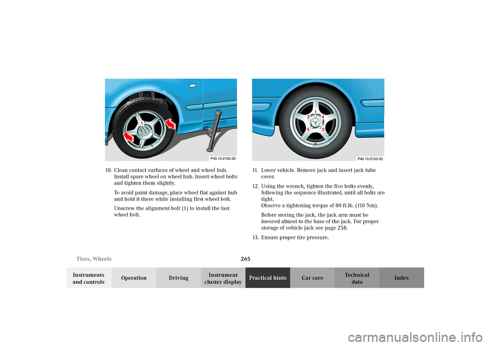
cluster displayPractical hintsCar care Index 10. Clean contact surfaces of wheel and wheel hub.
Install spare wheel on wheel hub. Insert wheel bolts
and tighten them slightly.
To avoid paint damage, place wheel flat against hub
and hold it there while installing first wheel bolt.
Unscrew the alignment bolt (1) to install the last
wheel bolt.11. Lower vehicle. Remove jack and insert jack tube
cover.
12. Using the wrench, tighten the five bolts evenly,
following the sequence illustrated, until all bolts are
tight.
Observe a tightening torque of 80 ft.lb. (110 Nm).
Before storing the jack, the jack arm must be
lowered almost to the base of the jack. For proper
storage of vehicle jack see page 258.
13. Ensure proper tire pressure.
1
1
J_C208_II.book Seite 265 Donnerstag, 31. Mai 2001 10:13 10
Page 304 of 330

301 Technical data
Technical
data Instruments
and controlsOperation DrivingInstrument
cluster displayPractical hints Car care Index Technical data
Model CLK 430 (208.370)
1
CLK 55 AMG (208.374)
1
Engine113 113
Mode of operation 4-stroke engine,
gasoline injection4-stroke engine,
gasoline injection
No. of cylinders 8 8
Bore 3.54 in (89.90 mm) 3.82 in (97.00 mm)
Stroke 3.30 in (84.00 mm) 3.60 in (92.00 mm)
Total piston displacement 260.3 cu.in. (4265 cm
3) 322.0 cu.in. (5439 cm
3)
Compression ratio 10:1 10.5:1
Output acc. to SAE J 1349 275 hp/5750 rpm
(205 kW/5750 rpm)342 hp/5500 rpm
(255 kW/5500 rpm)
Maximum torque acc. to SAE J 1349 295 ft.lb/3200 rpm
(400 Nm/3200 rpm)376 ft.lb/3000 rpm
(510 Nm/3000 rpm)
Maximum engine speed 6000 rpm 6000 rpm
Firing order 1-5-4-2-6-3-7-8 1-5-4-2-6-3-7-8
Poly-V-belt 2390 mm 2390 mm
1 The quoted data apply only to the standard vehicle. See an authorized Mercedes-Benz
Center for the corresponding data of all special bodies and special equipment.
J_C208_II.book Seite 301 Donnerstag, 31. Mai 2001 10:13 10
Page 306 of 330

303 Technical data
Technical
data Instruments
and controlsOperation DrivingInstrument
cluster displayPractical hints Car care Index Rims – Winter tires
Electrical system Model CLK 430 CLK 55 AMG
Rim (light alloy)
Wheel offset7 J x 16 H 2
1.46 in (37 mm)7
1/2 J x 17 H 2
1.46 in (37 mm)
Winter tires:
Radial-ply tires 205/55 R 16 91 H M+S 225/45 R 17 91 W M+S
Model CLK 430 CLK 55 AMG
Generator (alternator) 14 V/150 A 14 V/150 A
Starter motor 12V/1.7 kW 12V/1.7 kW
B a t t e r y 12 V / 10 0 A h12 V / 10 0 A h
Spark plugs
Electrode gap
Tightening torqueBosch F 8 DPER
Beru 14 FGH 8 DPUR X 2
0.039 in (1.0 mm)
15–22ft.lb (20–30Nm)NGK PFR 5-11
0.039 in (1.0 mm)
15–22ft.lb (20–30Nm)
J_C208_II.book Seite 303 Donnerstag, 31. Mai 2001 10:13 10