2002 MERCEDES-BENZ CLK430 CABRIOLET warning lights
[x] Cancel search: warning lightsPage 118 of 346

115 Exterior lamp switch
Technical
data Instruments
and controlsOperationDrivingInstrument
cluster displayPractical hints Car care Index Notes:
With the electronic key removed and the driver’s door
open, a warning sounds and the message “SWITCH OFF
LIGHTS” in the multifunction indicator appears if the
vehicle’s exterior lamps (except standing lamps) are not
switched off.
Fog lamps will operate with the parking lamps and/or
the low beam headlamps on. Fog lamps should only be
used in conjunction with low beam headlamps. Consult
your State or Province Motor Vehicle Regulations
regarding allowable lamp operation.
Fog lamps are automatically switched off when the
exterior lamp switch is turned to position D.Daytime running lamps (Canada only)
When the engine is running and the selector lever is in
a driving position, the low beam headlamps (includes
parking lamps, side marker lamps, taillamps and
license plate lamps) are automatically switched on.
When shifting from a driving position to position “N”
or “P”, the low beam switches off (2 seconds delay).
For nighttime driving the exterior lamp switch should
be turned to position B to permit activation of the
high beam headlamps.
Night security illumination
When exiting the vehicle after driving with the exterior
lamps on, they switch on again for added illumination
for approximately 30 seconds after closing the last door.
The lamp-on time period can be changed at your
Mercedes-Benz Center.
J_A208.book Seite 115 Donnerstag, 31. Mai 2001 9:35 09
Page 234 of 346

231 Malfunction and indicator lamps
Technical
data Instruments
and controlsOperation DrivingInstrument
cluster displayPractical hints Car care Index Electronic stability program (ESP) — warning lamp
The yellow ESP warning lamp in the
speedometer dial comes on with the
electronic key in steering lock position 2.
It should go out with engine running.
See page 220 if the warning lamp lights up or flashes
when the vehicle is moving.
BAS / ESP malfunction indicator lamp
The malfunction indicator lamp for the ESP
is combined with that of the BAS.
The yellow BAS/ESP malfunction indicator
lamp in the instrument cluster comes on with the
electronic key in steering lock position 2. It should go
out with the engine running.
If the BAS/ESP malfunction indicator lamp remains
illuminated with the engine running, see page 216 for
notes on the brake assist (BAS) and page 220 for notes
on the electronic stability program (ESP).ABS malfunction indicator lamp
The ABS malfunction indicator lamp in the
instrument cluster comes on with the
electronic key in steering lock position 2 and
should go out with the engine running.
When the ABS malfunction indicator lamp and the
malfunction message in the instrument cluster remains
illuminated while the engine is running, it indicates
that the ABS has detected a malfunction and has
switched off. In this case, the brake system functions in
the usual manner, but without antilock assistance.
With the ABS malfunctioning, the BAS and ESP are also
switched off. Both malfunction indicator lamps and the
ABS malfunction message in the multifunction display
come on with the engine running.
If the charging voltage falls below 10 volts, the
malfunction indicator lamp comes on and the ABS is
switched off. When the voltage is above this value again,
the malfunction indicator lamp should go out and the
ABS is operational.
Have the system checked at your authorized
Mercedes-Benz Center as soon as possible.
See page 218 for notes on the antilock brake system
(ABS).
BAS
ESP
ABS
J_A208.book Seite 231 Donnerstag, 31. Mai 2001 9:35 09
Page 237 of 346

234 Malfunction and warning messages
Technical
data Instruments
and controlsOperation DrivingInstrument
cluster displayPractical hints Car care Index
Malfunction and warning messages in the
multifunction display
Malfunction and warning messages for the following
systems will be displayed immediately in the
multifunction display.
These messages can be cleared from the instrument
cluster by:
•using the J button on the instrument cluster, or
•pressing buttonj, k, è or ÿ on the
multifunction steering wheel.
They are then stored in the malfunction message
memory. See page 104.Notes:
Certain malfunction and warning messages are
accompanied by an audible signal.
Malfunction and warning messages in red are always
accompanied by an audible signal.
Temporary messages such as “SWITCH OFF LIGHTS”
will not be stored in the malfunction message memory.
Wa r n i n g !
All messages contain important information which
should be taken note of and, where malfunction
indicated, addressed as soon as possible at an
authorized Mercedes-Benz Center.Failure to repair condition noted may cause
damage not covered by the Mercedes-Benz Limited
Warranty, or result in property damage or personal
injury.
J_A208.book Seite 234 Donnerstag, 31. Mai 2001 9:35 09
Page 246 of 346

243 Malfunction and warning messages
Technical
data Instruments
and controlsOperation DrivingInstrument
cluster displayPractical hints Car care Index LIGHT SENSOR
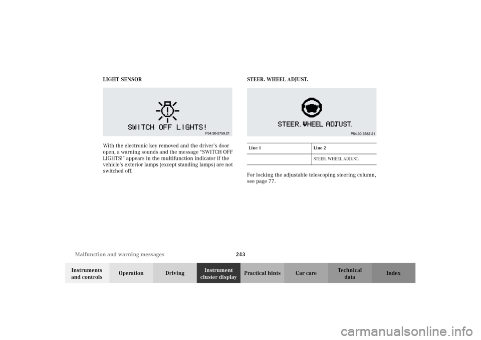
With the electronic key removed and the driver’s door
open, a warning sounds and the message “SWITCH OFF
LIGHTS!” appears in the multifunction indicator if the
vehicle’s exterior lamps (except standing lamps) are not
switched off.STEER. WHEEL ADJUST.
For locking the adjustable telescoping steering column,
see page 77.
Line 1 Line 2
STEER. WHEEL ADJUST.
J_A208.book Seite 243 Donnerstag, 31. Mai 2001 9:35 09
Page 278 of 346

275 Jump starting
Technical
data Instruments
and controlsOperation DrivingInstrument
cluster displayPractical hintsCar care Index Proceed as follows:
1. Position the vehicle with the charged battery so that
the jumper cables will reach, but never let the
vehicles touch. Make sure the jumper cables do not
have loose or missing insulation.
2. On both vehicles:
•Turn off engine and all lights and accessories,
except hazard warning flashers or work lights.
•Apply parking brake and shift selector lever to
position “P”.
Important!
3. Clamp one end of the first jumper cable to the
positive (+) under hood terminal of the discharged
battery and the other end to the positive (+) terminal
of the charged battery. Make sure the cable clamps
do not touch any other metal parts.
4. Clamp one end of the second jumper cable to the
grounded negative (–) terminal of the charged
battery and the final connection to the negative (–)
terminal (2) of the discharged battery.Important!
5. Start engine of the vehicle with the charged battery
and run at high idle. Make sure the cables are not
on or near pulleys, fans, or other parts that move
when the engine is started. Allow the discharged
battery to charge for a few minutes. Start engine of
the disabled vehicle in the usual manner.
6. After the engine has started, remove jumper cables
by exactly reversing the above installation
sequence, starting with the last connection made
first. When removing each clamp, make sure that it
does not touch any other metal while the other end
is still attached.
Notes:
If engine does not run after several unsuccessful
starting attempts, have it checked at the nearest
authorized Mercedes-Benz Center.
Excessive unburned fuel may damage the catalytic
converter.
J_A208.book Seite 275 Donnerstag, 31. Mai 2001 9:35 09
Page 334 of 346

331 Index
Technical
data Instruments
and controlsOperation DrivingInstrument
cluster displayPractical hints Car careIndex
HHazard warning flasher switch ....................................119
Head restraints
Front ............................................................................. 51
Rear ............................................................................... 52
Removal ........................................................................ 51
Headlamp cleaning system ...........................................116
Headlights ........................................................................114
Heated seats ..................................................................... 56
High beams
See Combination switch ...........................................117
Hood ................................................................................. 254IIdentification labels ........................................................311
Illuminated vanity mirrors ........................................... 150
Indicator lamps in the instrument cluster ................... 84
Individual settings ......................................................... 106
Infant and child restraint systems ................................ 75
Information call
See Tele Aid ............................................................... 187
Instrument cluster ........................................................... 82
Activating display ....................................................... 85Indicator lamps ............................................................ 84
Instrument lamps ............................................................. 85
Instruments and controls ............................................... 18
Interior
General notes ............................................................. 151
Interior lighting .............................................................. 149
JJump starting .................................................................. 274KKeys, changing battery ................................................. 288
Keys, vehicle .....................................................................24LLamps, exterior
Fog lamps ................................................................... 114
Headlamp, adjusting ................................................ 285
Headlamps ...................... 114, 242, 243, 281, 285, 305
Low and high beam ........................................... 117, 282
Parking lamps ................................................... 114, 282
J_A208.book Seite 331 Donnerstag, 31. Mai 2001 9:35 09