Page 241 of 346
238 Malfunction and warning messages
Technical
data Instruments
and controlsOperation DrivingInstrument
cluster displayPractical hints Car care Index
BRAKE LINING WEAR
When this message appears during braking, it indicates
that the brake pads are worn down.
Have the brake system checked at your authorized
Mercedes-Benz Center as soon as possible.BRAKE FLUID
Line 1 Line 2
BRAKE LINING WEAR VISIT WORKSHOP!
Line 1 Line 2
BRAKE FLUID VISIT WORKSHOP!Wa r n i n g !
Driving with this message displayed can result in
an accident. Have your brake system checked
immediately. Don’t add brake f luid before checking
the brake system. Overfilling the brake fluid
reservoir can result in spilling brake fluid on hot
engine parts and the brake fluid catching fire. You
can be seriously burned.
J_A208.book Seite 238 Donnerstag, 31. Mai 2001 9:35 09
Page 242 of 346
239 Malfunction and warning messages
Technical
data Instruments
and controlsOperation DrivingInstrument
cluster displayPractical hints Car care Index PA R K I N G B R A K E
Parking brake, see page 204.ENGINE FAN
1 The cooling fan for the coolant is faulty. Observe coolant
temperature gauge while driving, see page 86. Line 1 Line 2
PARKING BRAKE RELEASE BRAKE!Line 1 Line 2
ENGINE FAN VISIT WORKSHOP!
1
J_A208.book Seite 239 Donnerstag, 31. Mai 2001 9:35 09
Page 245 of 346
242 Malfunction and warning messages
Technical
data Instruments
and controlsOperation DrivingInstrument
cluster displayPractical hints Car care Index
LIGHTING SYSTEMWhen the message appears after starting the engine, or
if it comes on while driving, this indicates a failure in
the parking lamp, taillamp, stop lamp, or low beam
headlamp. See page 280 for instructions on replacing
bulbs.
If an exterior lamp fails, the message will appear only
when that lamp is switched on.
If a brake lamp fails, the message will appear when
applying the brake and stays on until the engine is
turned off.
Note:
If additional lighting is installed (e.g. auxiliary
headlamps etc.) be certain to connect into the fuse
before the failure indicator monitoring unit order to
avoid damaging the system.
Line 1 Line 2
LAMP DEFECTIVE CHECK LAMPS!
DISPLAY DEFECTIVE VISIT WORKSHOP!
J_A208.book Seite 242 Donnerstag, 31. Mai 2001 9:35 09
Page 264 of 346

261 Spare wheel, vehicle jack
Technical
data Instruments
and controlsOperation DrivingInstrument
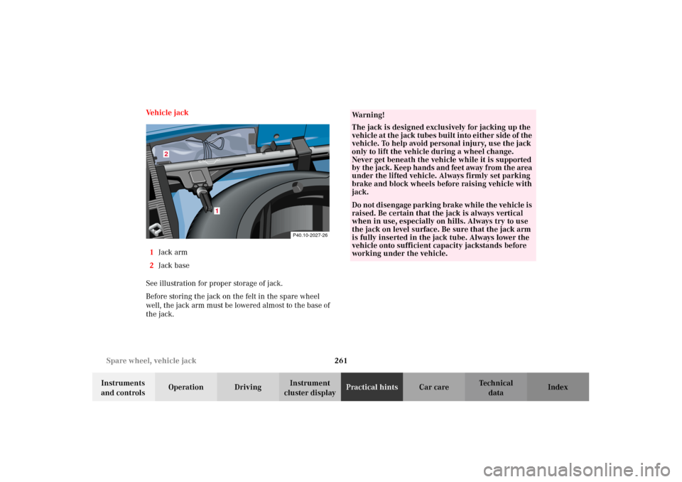
cluster displayPractical hintsCar care Index Ve h i c l e j a c k
1Jack arm
2Jack base
See illustration for proper storage of jack.
Before storing the jack on the felt in the spare wheel
well, the jack arm must be lowered almost to the base of
the jack.
1
2
P40.10-2027-26
Wa r n i n g !
The jack is designed exclusively for jacking up the
vehicle at the jack tubes built into either side of the
vehicle. To help avoid personal injury, use the jack
only to lift the vehicle during a wheel change.
Never get beneath the vehicle while it is supported
by the ja ck. Keep ha nd s an d feet away from the area
under the lifted vehicle. Always firmly set parking
brake and block wheels before raising vehicle with
jack.Do not d i sen ga ge park in g b ra ke whi l e the vehic l e is
raised. Be certain that the jack is always vertical
when in use, especially on hills. Always try to use
the jack on level surface. Be sure that the jack arm
is fully inserted in the jack tube. Always lower the
vehicle onto sufficient capacity jackstands before
working under the vehicle.
J_A208.book Seite 261 Donnerstag, 31. Mai 2001 9:35 09
Page 269 of 346

266 Tires, Wheels
Technical
data Instruments
and controlsOperation DrivingInstrument
cluster displayPractical hintsCar care Index
Changing wheelsMove vehicle to a level area which is a safe distance
from the roadway.
1. Set parking brake and turn on hazard warning
flasher.
2. Move selector lever to position “P” and turn off
engine.
3. Prevent vehicle from rolling away by blocking
wheels with wheel chocks (not supplied with
vehicle) or sizable wood block or stone. When
changing a wheel on a hill, place chocks on the
downhill side blocking both wheels of the other
axle. On a level road, place one chock in front of and
one behind the wheel that is diagonally opposite to
the wheel being changed.
Wa r n i n g !
The jack is designed exclusively for jacking up the
vehicle at the jack tubes built into either side of the
vehicle. To help avoid personal injury, use the jack
only to lift the vehicle during a wheel change.
Never get beneath the vehicle while it is supported
by t he j ack . Keep han ds a nd feet away from t he a rea
under the lifted vehicle. Always firmly set parking
brake and block wheels before raising vehicle with
jack.Do n ot d is engage parki n g brake w hil e t he vehi c le i s
raised. Be certain that the jack is always vertical
when in use, especially on hills. Always try to use
the jack on level surface. Be sure that the jack arm
is fully inserted in the jack tube. Always lower the
vehicle onto sufficient capacity jackstands before
working under the vehicle.
Wa r n i n g !
Before working on the vehicle, e.g. when changing
wheels, the roll bar should be raised with the
switch, and the electronic key be removed from the
steering lock, to prevent possible injury.
J_A208.book Seite 266 Donnerstag, 31. Mai 2001 9:35 09
Page 278 of 346

275 Jump starting
Technical
data Instruments
and controlsOperation DrivingInstrument
cluster displayPractical hintsCar care Index Proceed as follows:
1. Position the vehicle with the charged battery so that
the jumper cables will reach, but never let the
vehicles touch. Make sure the jumper cables do not
have loose or missing insulation.
2. On both vehicles:
•Turn off engine and all lights and accessories,
except hazard warning flashers or work lights.
•Apply parking brake and shift selector lever to
position “P”.
Important!
3. Clamp one end of the first jumper cable to the
positive (+) under hood terminal of the discharged
battery and the other end to the positive (+) terminal
of the charged battery. Make sure the cable clamps
do not touch any other metal parts.
4. Clamp one end of the second jumper cable to the
grounded negative (–) terminal of the charged
battery and the final connection to the negative (–)
terminal (2) of the discharged battery.Important!
5. Start engine of the vehicle with the charged battery
and run at high idle. Make sure the cables are not
on or near pulleys, fans, or other parts that move
when the engine is started. Allow the discharged
battery to charge for a few minutes. Start engine of
the disabled vehicle in the usual manner.
6. After the engine has started, remove jumper cables
by exactly reversing the above installation
sequence, starting with the last connection made
first. When removing each clamp, make sure that it
does not touch any other metal while the other end
is still attached.
Notes:
If engine does not run after several unsuccessful
starting attempts, have it checked at the nearest
authorized Mercedes-Benz Center.
Excessive unburned fuel may damage the catalytic
converter.
J_A208.book Seite 275 Donnerstag, 31. Mai 2001 9:35 09
Page 281 of 346

278 Towing
Technical
data Instruments
and controlsOperation DrivingInstrument
cluster displayPractical hintsCar care Index
We recommend that the vehicle be transported using
flat bed equipment. This method is preferable to other
types of towing.
The vehicle may be towed with all wheels on the ground
and the selector lever in position “N” for distances up to
30 miles (50 km) and at a speed not to exceed 30 mph
(50 km/h). The electronic key must be in steering lock
position 2.
To be certain to avoid a possibility of damage to the
transmission, however, we recommend the drive shaft
be disconnected at the rear axle drive flange for any
towing beyond a short tow to a nearby garage.
Do not tow with sling-type equipment. Towing with
sling-type equipment over bumpy roads will damage
radiator and supports.
Use wheel lift, dolly, or flat bed equipment, with
electronic key in steering lock turned to position 0.Note:
To signal turns while being towed with hazard warning
flasher in use, turn electronic key in steering lock to
position 2 and activate combination switch for left or
right turn signal in usual manner – only the selected
turn signal will operate.
Upon canceling the turn signal, the hazard warning
flasher will operate again.
Caution!
If the vehicle is towed with the front axle raised, the
engine must be shut off (electronic key in steering lock
position 0 or 1). Otherwise, the ESP will immediately be
engaged and will apply the rear wheel brakes. Switch off
the tow-away alarm (see page 44) as well as the ESP (see
page 222).
Wa r n i n g !
With the engine not running, there is no power
assistance for the braking and steering systems. In
this case, it is important to keep in mind that a
considerably higher degree of effort is necessary to
brake and steer the vehicle.
J_A208.book Seite 278 Donnerstag, 31. Mai 2001 9:35 09
Page 288 of 346
285 Exterior lamps
Technical
data Instruments
and controlsOperation DrivingInstrument
cluster displayPractical hintsCar care Index High mounted stop lamp,
Additional turn signals on the exterior mirror
The high mounted stop lamp (3rd brake lamp), and the
additional turn signals on the exterior mirrors are
equipped with LEDs.
Have the system checked at an authorized
Mercedes-Benz Center if a fault or defect occurs.Adjusting headlamp aim
Correct headlamp adjustment is extremely important.
To check and readjust a headlamp, follow steps 1
through 5.
Please note:
•Low beam adjustments simultaneously aim the high
beam.
•Vehicle should have a normal trunk load.
1. Park vehicle on level surface approximately 25 ft.
(7.6 m) from a vertical test screen or wall. The
centerline of the vehicle must be at a 90
° angle to
the test screen.
J_A208.book Seite 285 Donnerstag, 31. Mai 2001 9:35 09