Page 262 of 346

259 Engine compartment
Technical
data Instruments
and controlsOperation DrivingInstrument
cluster displayPractical hintsCar care Index Windshield washer / headlamp cleaning system
1Windshield washer/headlamp cleaning system fluid
reservoir
Capacity approx. 7.4 US qt (7.0 l).
The reservoir should be refilled with MB Windshield
washer concentrate and water (or commercially
available premixed windshield washer solvent/
antifreeze, depending on ambient temperatures).Windshield and headlamp washer
fluid mixing ratio
For temperatures above freezing:
MB Windshield Washer Concentrate “S” and water.
1 part “S” to 100 parts water
(40 ml “S” to 1 gallon water).
For temperature below freezing:
MB Windshield Washer Concentrate “S” and
commercially available premixed windshield washer
solvent/antifreeze.
1 part “S” to 100 parts solvent
(40 ml “S” to 1 gallon solvent).
1
P82.35-2017-26
Wa r n i n g !
Washer solvent/antifreeze is highly flammable. Do
not spill washer solvent/antifreeze on hot engine
parts, because it may burn. You can be seriously
burned.
J_A208.book Seite 259 Donnerstag, 31. Mai 2001 9:35 09
Page 274 of 346

271 Tires, Wheels
Technical
data Instruments
and controlsOperation DrivingInstrument
cluster displayPractical hintsCar care Index Tire inflation pressure
A table (see fuel filler flap) lists the tire inflation
pressures specified for Mercedes-Benz recommended
tires as well as for the varying operating conditions.
Important!
Tire pressure changes by approx. 1.5 psi (0.1 bar) per
18
°F (10
°C) of air temperature change. Keep this in
mind when checking tire pressure inside a garage –
especially in the winter.
Example:
If garage temperature = approx. +68
°F (+20
°C) and
ambient temperature = approx. +32
°F (0
°C) then the
adjusted air pressure = specified air pressure +3 psi
(+0.2 bar).Tire pressures listed for light loads are minimum values
offering high driving comfort. Increased inflation
pressures for heavy loads produce favorable handling
characteristics with lighter loads and are perfectly
permissible. The ride of the vehicle, however, will
become somewhat harder.
Tire temperature and pressure increase with the vehicle
speed. Tire pressure should therefore only be checked
and corrected on cold tires. Correct tire pressure in
warm tires only if pressure has dropped below the
pressure listed in the table and the respective operating
conditions are taken into consideration.
An underinflated tire due to a slow leak (e.g. due to a
nail in the tire) may cause damage such as tread
separation, bulging etc.. Regular tire pressure checks
(including the spare tire) at intervals of no more than
14 days are therefore essential.
J_A208.book Seite 271 Donnerstag, 31. Mai 2001 9:35 09
Page 278 of 346
275 Jump starting
Technical
data Instruments
and controlsOperation DrivingInstrument
cluster displayPractical hintsCar care Index Proceed as follows:
1. Position the vehicle with the charged battery so that
the jumper cables will reach, but never let the
vehicles touch. Make sure the jumper cables do not
have loose or missing insulation.
2. On both vehicles:
•Turn off engine and all lights and accessories,
except hazard warning flashers or work lights.
•Apply parking brake and shift selector lever to
position “P”.
Important!
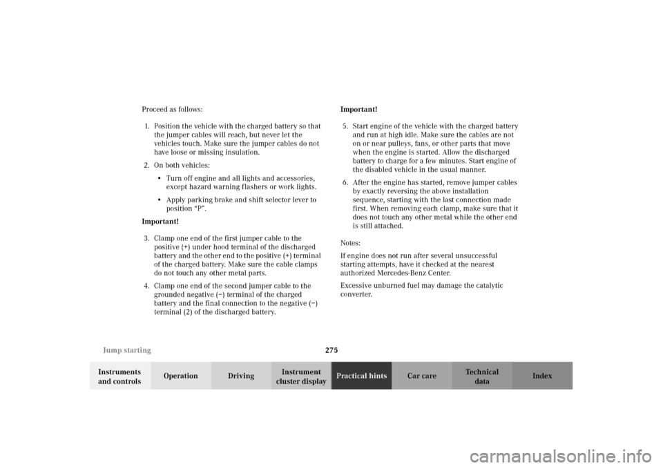
3. Clamp one end of the first jumper cable to the
positive (+) under hood terminal of the discharged
battery and the other end to the positive (+) terminal
of the charged battery. Make sure the cable clamps
do not touch any other metal parts.
4. Clamp one end of the second jumper cable to the
grounded negative (–) terminal of the charged
battery and the final connection to the negative (–)
terminal (2) of the discharged battery.Important!
5. Start engine of the vehicle with the charged battery
and run at high idle. Make sure the cables are not
on or near pulleys, fans, or other parts that move
when the engine is started. Allow the discharged
battery to charge for a few minutes. Start engine of
the disabled vehicle in the usual manner.
6. After the engine has started, remove jumper cables
by exactly reversing the above installation
sequence, starting with the last connection made
first. When removing each clamp, make sure that it
does not touch any other metal while the other end
is still attached.
Notes:
If engine does not run after several unsuccessful
starting attempts, have it checked at the nearest
authorized Mercedes-Benz Center.
Excessive unburned fuel may damage the catalytic
converter.
J_A208.book Seite 275 Donnerstag, 31. Mai 2001 9:35 09
Page 281 of 346
278 Towing
Technical
data Instruments
and controlsOperation DrivingInstrument
cluster displayPractical hintsCar care Index
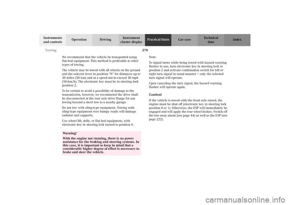
We recommend that the vehicle be transported using
flat bed equipment. This method is preferable to other
types of towing.
The vehicle may be towed with all wheels on the ground
and the selector lever in position “N” for distances up to
30 miles (50 km) and at a speed not to exceed 30 mph
(50 km/h). The electronic key must be in steering lock
position 2.
To be certain to avoid a possibility of damage to the
transmission, however, we recommend the drive shaft
be disconnected at the rear axle drive flange for any
towing beyond a short tow to a nearby garage.
Do not tow with sling-type equipment. Towing with
sling-type equipment over bumpy roads will damage
radiator and supports.
Use wheel lift, dolly, or flat bed equipment, with
electronic key in steering lock turned to position 0.Note:
To signal turns while being towed with hazard warning
flasher in use, turn electronic key in steering lock to
position 2 and activate combination switch for left or
right turn signal in usual manner – only the selected
turn signal will operate.
Upon canceling the turn signal, the hazard warning
flasher will operate again.
Caution!
If the vehicle is towed with the front axle raised, the
engine must be shut off (electronic key in steering lock
position 0 or 1). Otherwise, the ESP will immediately be
engaged and will apply the rear wheel brakes. Switch off
the tow-away alarm (see page 44) as well as the ESP (see
page 222).
Wa r n i n g !
With the engine not running, there is no power
assistance for the braking and steering systems. In
this case, it is important to keep in mind that a
considerably higher degree of effort is necessary to
brake and steer the vehicle.
J_A208.book Seite 278 Donnerstag, 31. Mai 2001 9:35 09
Page 283 of 346
280 Exterior lamps
Technical
data Instruments
and controlsOperation DrivingInstrument
cluster displayPractical hintsCar care Index
Exterior lamps
Headlamp adjustment
Correct headlamp adjustment is extremely important.
Check and readjust headlamps at regular intervals and
when a bulb has been replaced.
For adjusting headlamp aim see page 285.
Replacing bulbsNotes:
To prevent a possible electrical short circuit, switch off
lamp prior to replacing a bulb.
When replacing bulbs, install only 12 volt bulbs with
the specified watt rating.
When replacing halogen bulbs do not touch glass
portion of bulb with bare hands. Use plain paper or a
clean cloth.
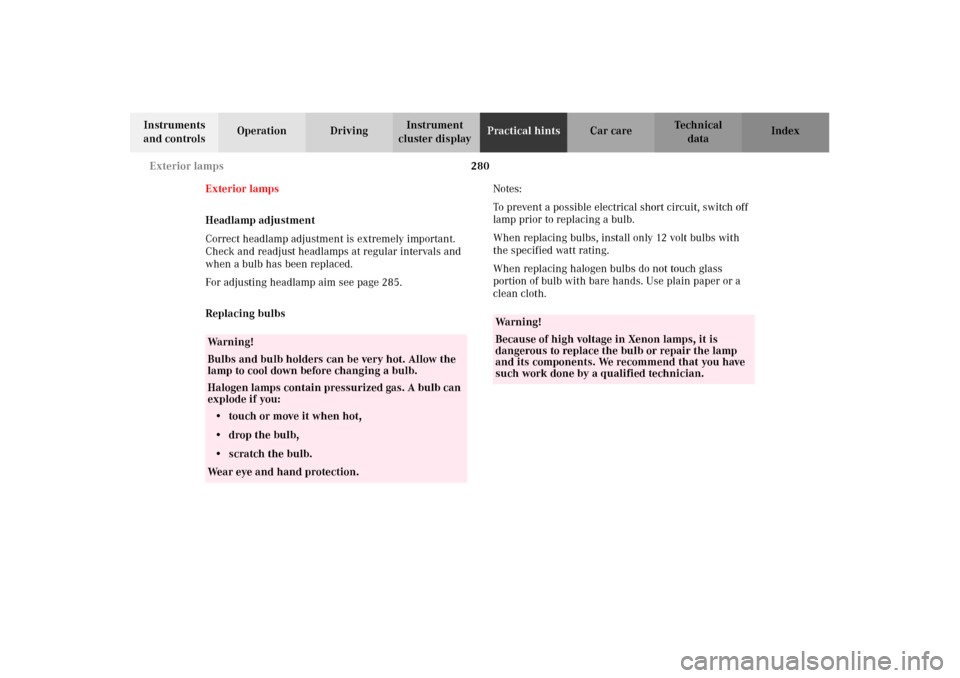
Wa r n i n g !
Bulbs and bulb holders can be very hot. Allow the
lamp to cool down before changing a bulb.
Halogen lamps contain pressurized gas. A bulb can
explode if you:
• touch or move it when hot,
•drop the bulb,
• scratch the bulb.Wear eye and hand protection.
Wa r n i n g !
Because of high voltage in Xenon lamps, it is
dangerous to replace the bulb or repair the lamp
and its components. We recommend that you have
such work done by a qualified technician.
J_A208.book Seite 280 Donnerstag, 31. Mai 2001 9:35 09
Page 284 of 346
281 Exterior lamps
Technical
data Instruments
and controlsOperation DrivingInstrument
cluster displayPractical hintsCar care Index Headlamp assembly (Halogen)
1Headlamp vertical adjustment screw
2Cover for low beam headlamp
3Cover for high beam headlamp, parking and
standing lampHeadlamp assembly (Xenon)
(optional, standard on model CLK 55 AMG)
4Bulb socket for turn signal lamp
5Electrical connector for low beam headlamp bulb
6Electrical connector for high beam headlamp bulb
7Bulb socket for parking and standing lamp
P82.10-2394-26
4
1
5
6
7
2
3
4
6
7
2
3P82.10-2395-26
5
1
J_A208.book Seite 281 Donnerstag, 31. Mai 2001 9:35 09
Page 285 of 346
282 Exterior lamps
Technical
data Instruments
and controlsOperation DrivingInstrument
cluster displayPractical hintsCar care Index
Bulbs for low or high beam
H7 (55 W)
Open hood.
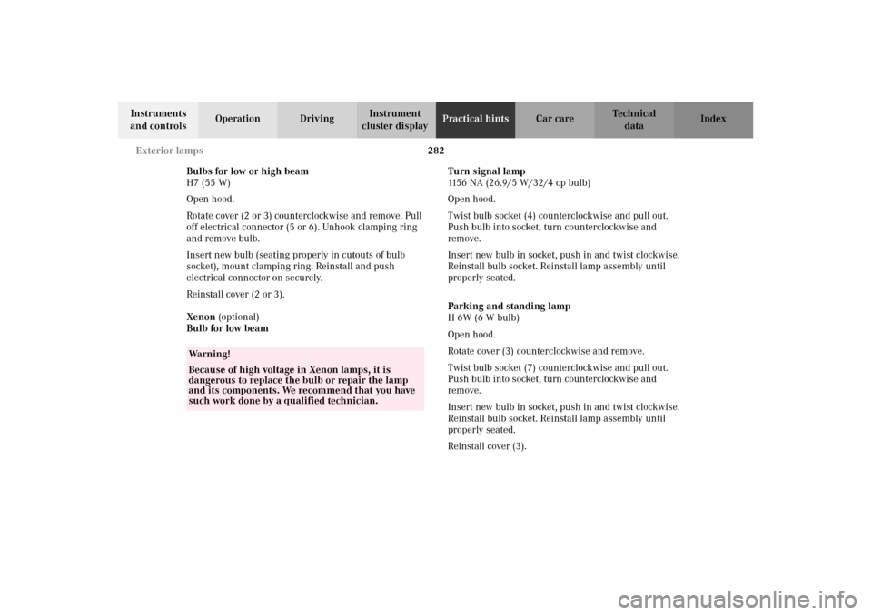
Rotate cover (2 or 3) counterclockwise and remove. Pull
off electrical connector (5 or 6). Unhook clamping ring
and remove bulb.
Insert new bulb (seating properly in cutouts of bulb
socket), mount clamping ring. Reinstall and push
electrical connector on securely.
Reinstall cover (2 or 3).
Xenon (optional)
Bulb for low beamTurn signal lamp
1156 NA (26.9/5 W/32/4 cp bulb)
Open hood.
Twist bulb socket (4) counterclockwise and pull out.
Push bulb into socket, turn counterclockwise and
remove.
Insert new bulb in socket, push in and twist clockwise.
Reinstall bulb socket. Reinstall lamp assembly until
properly seated.
Parking and standing lamp
H6W (6Wbulb)
Open hood.
Rotate cover (3) counterclockwise and remove.
Twist bulb socket (7) counterclockwise and pull out.
Push bulb into socket, turn counterclockwise and
remove.
Insert new bulb in socket, push in and twist clockwise.
Reinstall bulb socket. Reinstall lamp assembly until
properly seated.
Reinstall cover (3).
Wa r n i n g !
Because of high voltage in Xenon lamps, it is
dangerous to replace the bulb or repair the lamp
and its components. We recommend that you have
such work done by a qualified technician.
J_A208.book Seite 282 Donnerstag, 31. Mai 2001 9:35 09
Page 288 of 346
285 Exterior lamps
Technical
data Instruments
and controlsOperation DrivingInstrument
cluster displayPractical hintsCar care Index High mounted stop lamp,
Additional turn signals on the exterior mirror
The high mounted stop lamp (3rd brake lamp), and the
additional turn signals on the exterior mirrors are
equipped with LEDs.
Have the system checked at an authorized
Mercedes-Benz Center if a fault or defect occurs.Adjusting headlamp aim
Correct headlamp adjustment is extremely important.
To check and readjust a headlamp, follow steps 1
through 5.
Please note:
•Low beam adjustments simultaneously aim the high
beam.
•Vehicle should have a normal trunk load.
1. Park vehicle on level surface approximately 25 ft.
(7.6 m) from a vertical test screen or wall. The
centerline of the vehicle must be at a 90
° angle to
the test screen.
J_A208.book Seite 285 Donnerstag, 31. Mai 2001 9:35 09

