2002 MERCEDES-BENZ CLK-CLASS warning
[x] Cancel search: warningPage 244 of 341
241 Malfunction and warning messages
Te ch n i c a l
data Instruments
and controlsOperation DrivingInstrument
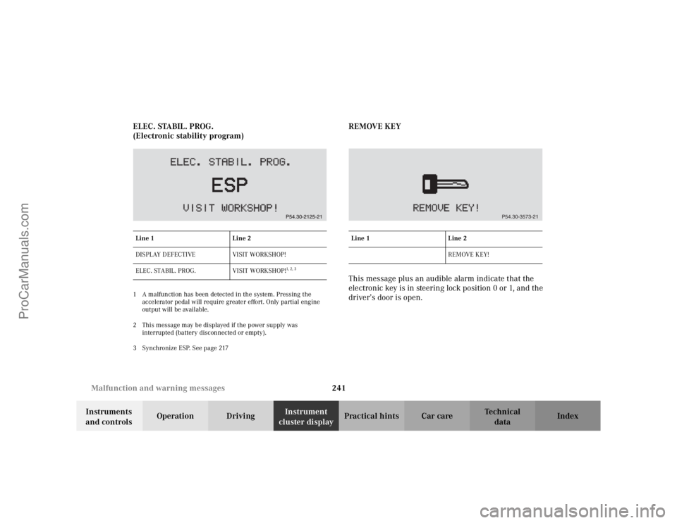
cluster displayPractical hints Car care Index ELEC. STABIL. PROG.
(Electronic stability program)
1 A malfunction has been detected in the system. Pressing the
accelerator pedal will require greater effort. Only partial engine
output will be available.
2 This message may be displayed if the power supply was
interrupted (battery disconnected or empty).
3 Synchronize ESP. See page 217
REMOVE KEY
This message plus an audible alarm indicate that the
electronic key is in steering lock position 0 or 1, and the
driver’s door is open.
Line 1 Line 2
DISPLAY DEFECTIVE VISIT WORKSHOP!
ELEC. STABIL. PROG. VISIT WORKSHOP!
1, 2 , 3
Line 1 Line 2
REMOVE KEY!
P54.30-3573-21
ProCarManuals.com
Page 245 of 341
242 Malfunction and warning messages
Te ch n i c a l
data Instruments
and controlsOperation DrivingInstrument
cluster displayPractical hints Car care Index
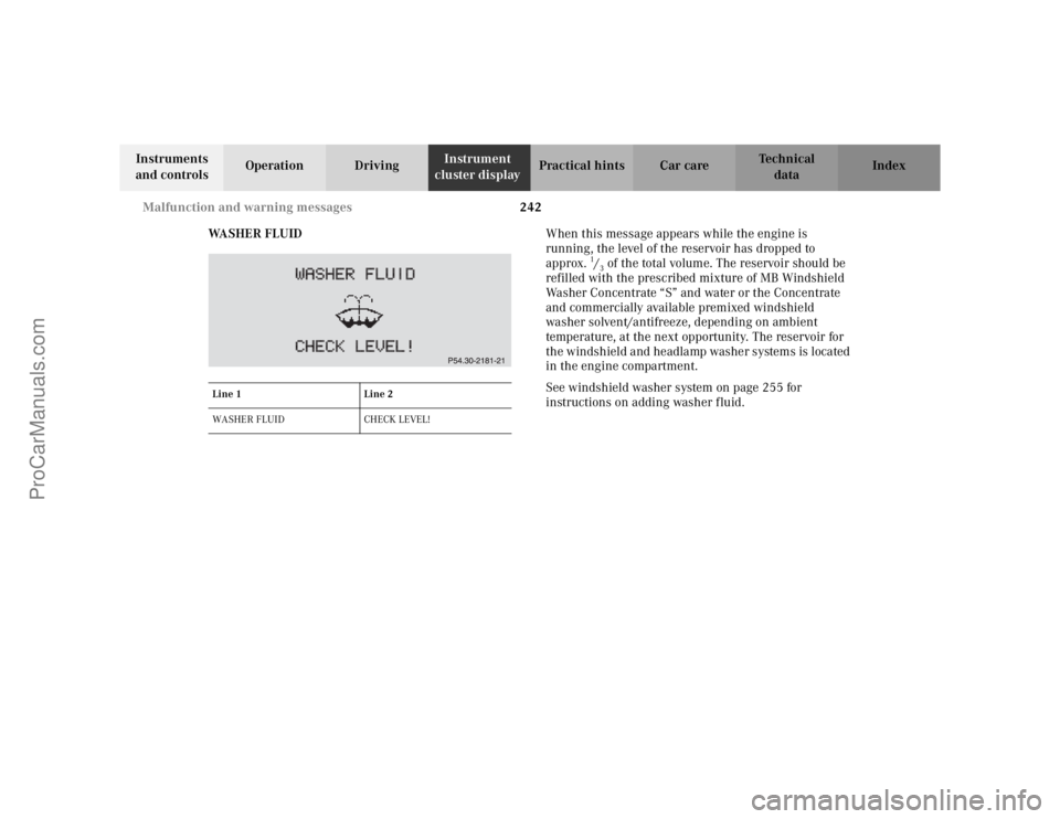
WA S H E R F L U I DWhen this message appears while the engine is
running, the level of the reservoir has dropped to
approx.
1/3 of the total volume. The reservoir should be
refilled with the prescribed mixture of MB Windshield
Washer Concentrate “S” and water or the Concentrate
and commercially available premixed windshield
washer solvent/antifreeze, depending on ambient
temperature, at the next opportunity. The reservoir for
the windshield and headlamp washer systems is located
in the engine compartment.
See windshield washer system on page 255 for
instructions on adding washer fluid.
Line 1 Line 2
WASHER FLUID CHECK LEVEL!
ProCarManuals.com
Page 246 of 341
243 Malfunction and warning messages
Te ch n i c a l
data Instruments
and controlsOperation DrivingInstrument
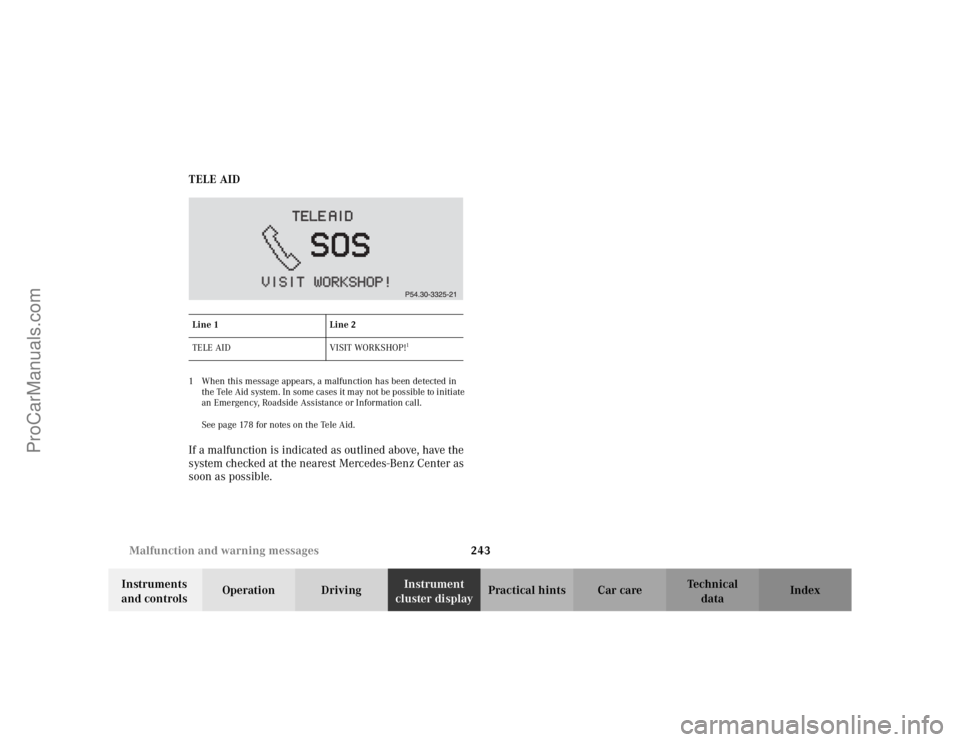
cluster displayPractical hints Car care Index TELE AID
1 When this message appears, a malfunction has been detected in
the Tele Aid system. In some cases it may not be possible to initiate
an Emergency, Roadside Assistance or Information call.
See page 178 for notes on the Tele Aid.If a malfunction is indicated as outlined above, have the
system checked at the nearest Mercedes-Benz Center as
soon as possible.Line 1 Line 2
TELE AID VISIT WORKSHOP!
1
ProCarManuals.com
Page 255 of 341
252 Engine compartment
Te ch n i c a l
data Instruments
and controlsOperation DrivingInstrument
cluster displayPractical hintsCar care Index
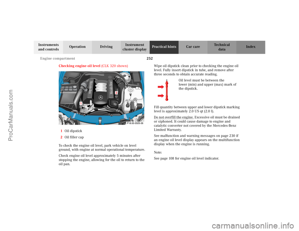
Checking engine oil level (CLK 320 shown)
1Oil dipstick
2Oil filler cap
To check the engine oil level, park vehicle on level
ground, with engine at normal operational temperature.
Check engine oil level approximately 5 minutes after
stopping the engine, allowing for the oil to return to the
oil pan.Wipe oil dipstick clean prior to checking the engine oil
level. Fully insert dipstick in tube, and remove after
three seconds to obtain accurate reading.
Oil level must be between the
lower (min) and upper (max) mark of
the dipstick.
Fill quantity between upper and lower dipstick marking
level is approximately 2.0 US qt (2.0 l).
Do not overfill the engine.
Excessive oil must be drained
or siphoned. It could cause damage to engine and
catalytic converter not covered by the Mercedes-Benz
Limited Warranty.
See malfunction and warning messages on page 230 if
an engine oil level display appears on the multifunction
display when the engine is running.
Note:
See page 108 for engine oil level indicator.
Mercedes-Benz
Mercedes-Benz
2
1
ProCarManuals.com
Page 266 of 341

263 Tires, Wheels
Te ch n i c a l
data Instruments
and controlsOperation DrivingInstrument
cluster displayPractical hintsCar care Index Changing wheelsMove vehicle to a level area which is a safe distance
from the roadway.
1. Set parking brake and turn on hazard warning
flasher.
2. Move selector lever to position “P” and turn off
engine.
3. Prevent vehicle from rolling away by blocking
wheels with wheel chocks (not supplied with
vehicle) or sizable wood block or stone. When
changing a wheel on a hill, place chocks on the
downhill side blocking both wheels of the other
axle. On a level road, place one chock in front of and
one behind the wheel that is diagonally opposite to
the wheel being changed.
Wa r n i n g !
The jack is designed exclusively for jacking up the
vehicle at the jack tubes built into either side of the
vehicle. To help avoid personal injury, use the jack
only to lift the vehicle during a wheel change.
Never get beneath the vehicle while it is supported
by the jack. Keep hands and feet away from the area
under the lifted vehicle. Always firmly set parking
brake and block wheels before raising vehicle with
jack.Do not disengage parking brake while the vehicle is
raised. Be certain that the jack is always vertical
when in use, especially on hills. Always try to use
the jack on level surface. Be sure that the jack arm
is fully inserted in the jack tube. Always lower the
vehicle onto sufficient capacity jackstands before
working under the vehicle.
Wa r n i n g !
Before working on the vehicle, e.g. when changing
wheels, the roll bar should be raised with the
switch, and the electronic key be removed from the
steering lock, to prevent possible injury.
ProCarManuals.com
Page 275 of 341

272 Jump starting
Te ch n i c a l
data Instruments
and controlsOperation DrivingInstrument
cluster displayPractical hintsCar care Index
Important!
A discharged battery can freeze at approx. +14
°F
(–10
°C). In that case, it must be thawed out before
jumper cables are used. Attempting to jump start a
frozen battery can result in it exploding, causing
personal injury.
Jumper cable specifications:
•Minimum cable cross-section of 25 mm
2 or approx.
2AWG
•Maximum length of 11.5 ft. (3.5 m).
If the battery is discharged, the engine should be started
with jumper cables and the (12 V) battery of another
vehicle.
Only use 12 V battery to jump start your vehicle. Jump
starting with more powerful battery could damage the
vehicle’s electrical systems, which will not be covered
by the Mercedes-Benz Limited Warranty.
The battery is located in the trunk under the trunk floor.Proceed as follows:
1. Position the vehicle with the charged battery so that
the jumper cables will reach, but never let the
vehicles touch. Make sure the jumper cables do not
have loose or missing insulation.
2. On both vehicles:
•Turn off engine and all lights and accessories,
except hazard warning flashers or work lights.
•Apply parking brake and shift selector lever to
position “P”.
Important!
3. Clamp one end of the first jumper cable to the
positive (+) terminal of the discharged battery and
the other end to the positive (+) terminal of the
charged battery. Make sure the cable clamps do not
touch any other metal parts.
4. Clamp one end of the second jumper cable to the
grounded negative (–) terminal of the charged
battery and the final connection to the negative (–)
terminal (2) of the discharged battery.
ProCarManuals.com
Page 278 of 341
275 Towing
Te ch n i c a l
data Instruments
and controlsOperation DrivingInstrument
cluster displayPractical hintsCar care Index With the automatic central locking activated and the
electronic key in steering lock position 2, the vehicle
doors lock if the left front wheel as well as the right rear
wheel are turning at vehicle speeds of approx. 9 mph
(15 km/h) or more. To prevent the vehicle doors from
locking, deactivate the automatic central locking, see
page 34.
Note:
To signal turns while being towed with hazard warning
flasher in use, turn electronic key in steering lock to
position 2 and activate combination switch for left or
right turn signal in usual manner – only the selected
turn signal will operate.
Upon canceling the turn signal, the hazard warning
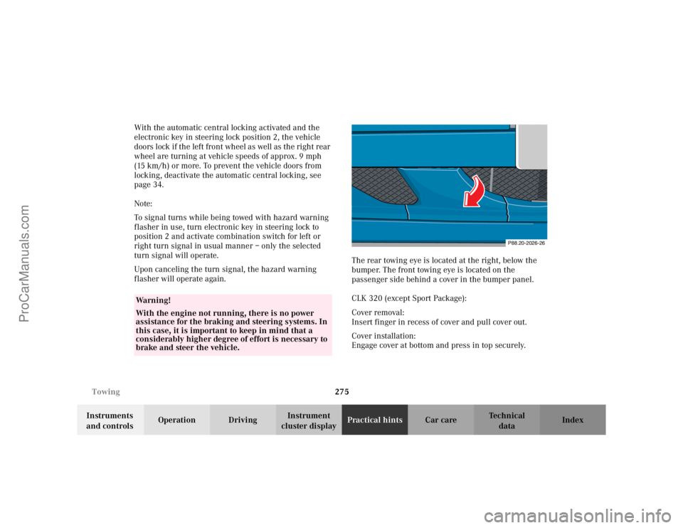
flasher will operate again.The rear towing eye is located at the right, below the
bumper. The front towing eye is located on the
passenger side behind a cover in the bumper panel.
CLK 320 (except Sport Package):
Cover removal:
Insert finger in recess of cover and pull cover out.
Cover installation:
Engage cover at bottom and press in top securely.
Wa r n i n g !
With the engine not running, there is no power
assistance for the braking and steering systems. In
this case, it is important to keep in mind that a
considerably higher degree of effort is necessary to
brake and steer the vehicle.
P88.20-2026-26
ProCarManuals.com
Page 327 of 341
324 Index
Te ch n i c a l
data Instruments
and controlsOperation DrivingInstrument
cluster displayPractical hints Car careIndex
Index
AABS (Antilock brake system) ....................................... 214
Malfunction indicator lamp..................................... 227
ABS-SYSTEM - malfunction and
warning messages ......................................................... 233
Adjusting headlamp aim............................................... 282
Adjusting telescoping steering column ........................ 73
Air conditioner refrigerant............................................ 318
Air distribution .............................................................. 120
Air volume ...................................................................... 120
Airbag deactivation system ............................................ 59
Airbag OFF indicator lamp ........................................... 228
Airbags .............................................................................. 61
Alarm system ............................................................. 39, 40
Antenna
Removal ...................................................................... 295
Anticorrosion/antifreeze .................... 208, 254, 316, 321
Antiglare night position.................................................. 74
Antilock brake system (ABS) ....................................... 214
Malfunction indicator lamp..................................... 227
Antitheft alarm system ................................................... 39
Aquaplaning ...................................................................205Armrest, rear bench ....................................................... 152
Ashtray
Center console, front ................................................ 150
Audio system ..................................................................123
Anti-theft system ....................................................... 125
Button and soft key operation ................................. 126
Cassette mode ............................................................ 131
CD changer ................................................................. 136
CD mode ..................................................................... 135
Operating and display elements .............................124
Operating safety ........................................................ 123
Operation ....................................................................127
Operation – audio and telephone ........................... 123
Radio mode ................................................................ 129
Telephone operation ................................................. 139
Audio systems ................................................................... 89
Cassette player ............................................................ 91
CD player ......................................................................90
Radio ............................................................................. 89
Automatic central locking .............................................. 34
Automatic climate control ............................................ 116
Air distribution .......................................................... 120
Air recirculation ........................................................ 121
Air volume.................................................................. 120
Basic setting............................................................... 118
Defogging windows ................................................... 119
ProCarManuals.com