2002 MERCEDES-BENZ CL55AMG warning lights
[x] Cancel search: warning lightsPage 273 of 430

270 Driving systems
Te ch n i c a l
data Instruments
and controlsOperationDrivingInstrument
cluster displayPractical hints Car care Index
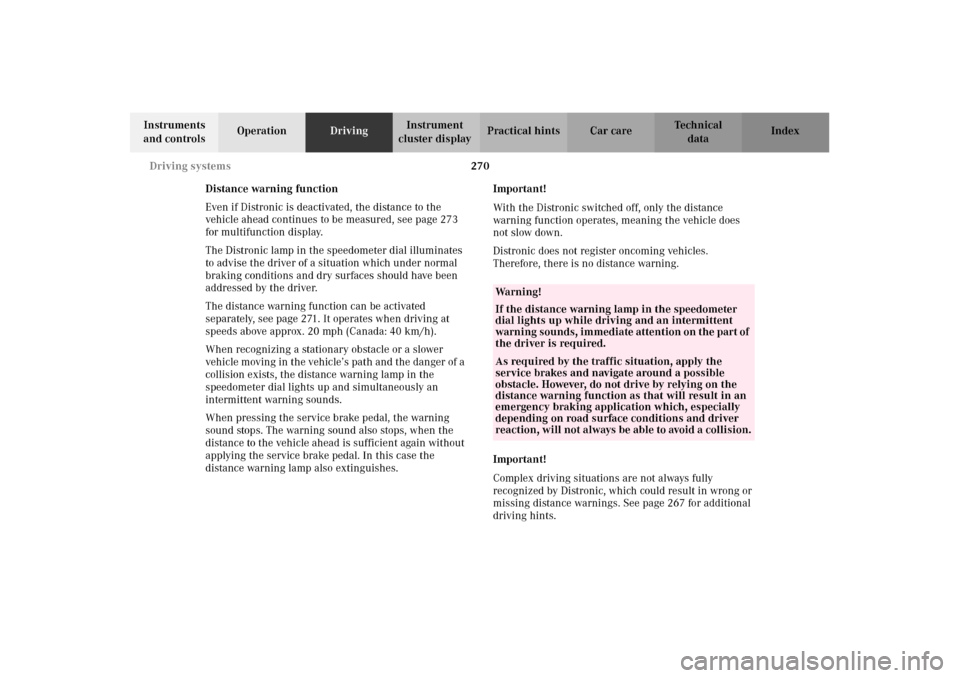
Distance warning function
Even if Distronic is deactivated, the distance to the
vehicle ahead continues to be measured, see page 273
for multifunction display.
The Distronic lamp in the speedometer dial illuminates
to advise the driver of a situation which under normal
braking conditions and dry surfaces should have been
addressed by the driver.
The distance warning function can be activated
separately, see page 271. It operates when driving at
speeds above approx. 20 mph (Canada: 40 km/h).
When recognizing a stationary obstacle or a slower
vehicle moving in the vehicle’s path and the danger of a
collision exists, the distance warning lamp in the
speedometer dial lights up and simultaneously an
intermittent warning sounds.
When pressing the service brake pedal, the warning
sound stops. The warning sound also stops, when the
distance to the vehicle ahead is sufficient again without
applying the service brake pedal. In this case the
distance warning lamp also extinguishes.Important!
With the Distronic switched off, only the distance
warning function operates, meaning the vehicle does
not slow down.
Distronic does not register oncoming vehicles.
Therefore, there is no distance warning.
Important!
Complex driving situations are not always fully
recognized by Distronic, which could result in wrong or
missing distance warnings. See page 267 for additional
driving hints.
Wa r n i n g !
If the distance warning lamp in the speedometer
dial lights up while driving and an intermittent
warning sounds, immediate attention on the part of
the driver is required.As required by the traffic situation, apply the
service brakes and navigate around a possible
obstacle. However, do not drive by relying on the
distance warning function as that will result in an
emergency braking application which, especially
depending on road surface conditions and driver
reaction, will not always be able to avoid a collision.
J_OM_215.book Seite 270 Mittwoch, 30. Mai 2001 2:01 14
Page 274 of 430

271 Driving systems
Te ch n i c a l
data Instruments
and controlsOperationDrivingInstrument
cluster displayPractical hints Car care Index Distronic settings
1Switch – for distance warning function
2Thumbwheel – for setting distance
Distronic provides a range of following distances to the
vehicle in front. The medium setting is noticeable by a
detent in the center position of the thumbwheel (2).
If you want to:
•Increase distance – turn thumbwheel (2)
towards¯.•Decrease distance – turn thumbwheel (2)
towards®.
To switch the distance warning function on or off:
To switch on – press upper half of switch (1).
The indicator lamp in the switch lights up. If the
Distronic menu is active in the multifunction display, a
loudspeaker symbol appears.
To switch off – press lower half of the switch (1).
The indicator lamp in the switch goes out. If the
Distronic menu is active in the multifunction display,
the loudspeaker symbol disappears.
See page 270 for distance warning function and
page 273 for multifunction displays.
Wa r n i n g !
It is up to the driver to exercise discretion to select
the appropriate setting given road conditions,
traffic, driver’s preferred driving style and
applicable laws and driving recommendations for
safe following distance.
J_OM_215.book Seite 271 Mittwoch, 30. Mai 2001 2:01 14
Page 291 of 430

288 Parking system
Te ch n i c a l
data Instruments
and controlsOperationDrivingInstrument
cluster displayPractical hints Car care Index
Warning indicators
1Frame
2SegmentsVisual and audible signals indicate to the driver the
relative distance between the vehicle and an obstacle.
Warning indicators for the front area are located above
the left and center air outlets in the dashboard.
Warning indicators for the rear area are integrated in
the rear headliner.
The frames (1) are illuminated when the Parktronic is
engaged.
Each warning indicator has 6 yellow and 2 red
segments (2).
As soon as the sensors detect an obstacle, one or more
segments light up, depending on the distance. An
intermittent acoustic warning will also sound as the
seventh segment lights up and a constant acoustic
warning lasting a maximum of 3 seconds will sound for
the eighth segment.
2
1
P54.65-2043-26
J_OM_215.book Seite 288 Mittwoch, 30. Mai 2001 2:01 14
Page 293 of 430

290 Parking system
Te ch n i c a l
data Instruments
and controlsOperationDrivingInstrument
cluster displayPractical hints Car care Index
The obstacle may not be recognized if outside the
shaded sensor field, and no longer be indicated when
approaching it any closer (warning indicators go out).
Parktronic malfunction
All red segments of the warning indicators light up, and
a warning sounds for 3 seconds, if Parktronic does not
function properly. The indicator lamp in the switch
lights up and the system switches off automatically!
A dirty sensor or other ultrasonic signals could be the
reason. See page 384 for instructions on cleaning the
sensors in the bumpers.
After cleaning the sensors, turn electronic key in starter
switch to position 2. If the defect continues to be
displayed, have the system checked at your authorized
Mercedes-Benz Center.Parktronic switch
The switch is located on the center console.
1Parktronic switched off
2Parktronic switched on
3Indicator lamp – comes on when Parktronic is
switched off
The parktronic system is switched on again when
turning the electronic key in starter switch position 2.3
J_OM_215.book Seite 290 Mittwoch, 30. Mai 2001 2:01 14
Page 304 of 430

301 Malfunction and indicator lamps
Te ch n i c a l
data Instruments
and controlsOperation DrivingInstrument
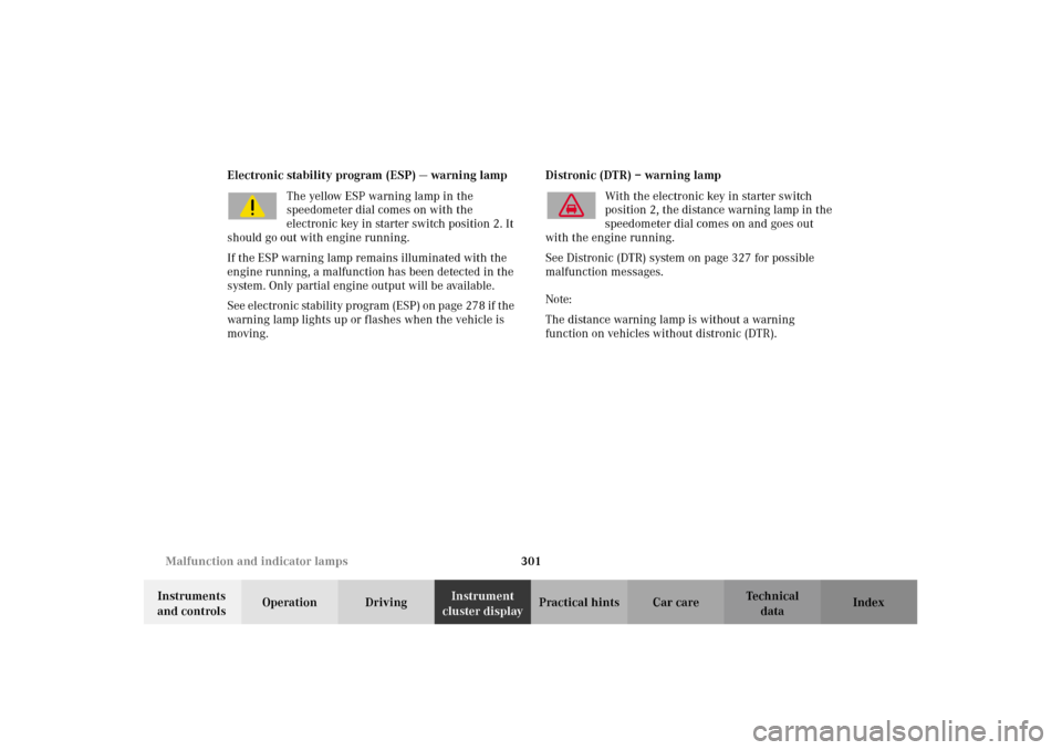
cluster displayPractical hints Car care Index Electronic stability program (ESP) — warning lamp
The yellow ESP warning lamp in the
speedometer dial comes on with the
electronic key in starter switch position 2. It
should go out with engine running.
If the ESP warning lamp remains illuminated with the
engine running, a malfunction has been detected in the
system. Only partial engine output will be available.
See elec tr on ic stability p rogram (ESP ) on p age 27 8 if t he
warning lamp lights up or flashes when the vehicle is
moving.Distronic (DTR) – warning lamp
With the electronic key in starter switch
position 2, the distance warning lamp in the
speedometer dial comes on and goes out
with the engine running.
See Distronic (DTR) system on page 327 for possible
malfunction messages.
Note:
The distance warning lamp is without a warning
function on vehicles without distronic (DTR).
J_OM_215.book Seite 301 Mittwoch, 30. Mai 2001 2:01 14
Page 359 of 430

356 Jump starting
Te ch n i c a l
data Instruments
and controlsOperation DrivingInstrument
cluster displayPractical hintsCar care Index
Proceed as follows:
1. Position the vehicle with the charged battery so that
the jumper cables will reach, but never let the
vehicles touch. Make sure the jumper cables do not
have loose or missing insulation.
2. On both vehicles:
•Turn off engine and all lights and accessories,
except hazard warning flashers or work lights.
•Apply parking brake and shift selector lever to
position “P”.
Important!
3. Clamp one end of the first jumper cable to the
positive (+) terminal of the discharged battery and
the other end to the positive (+) terminal of the
charged battery. Make sure the cable clamps do not
touch any other metal parts.
4. Clamp one end of the second jumper cable to the
grounded negative (–) terminal of the charged
battery and the final connection to the negative (–)
under hood terminal of the disabled vehicle.Important!
5. Start engine of the vehicle with the charged battery
and run at high idle. Make sure the cables are not
on or near pulleys, fans, or other parts that move
when the engine is started. Allow the discharged
battery to charge for a few minutes. Start engine of
the disabled vehicle in the usual manner.
6. After the engine has started, remove jumper cables
by exactly reversing the above installation
sequence, starting with the last connection made
first. When removing each clamp, make sure that it
does not touch any other metal while the other end
is still attached.
Notes:
If engine does not run after several unsuccessful
starting attempts, have it checked at the nearest
authorized Mercedes-Benz Center.
Excessive unburned fuel may damage the catalytic
converter.
J_OM_215.book Seite 356 Mittwoch, 30. Mai 2001 2:01 14
Page 415 of 430

412 Index
Te ch n i c a l
data Instruments
and controlsOperation DrivingInstrument
cluster displayPractical hints Car careIndex
FFastening seat belts ......................................................... 85
First aid kit ..................................................................... 330
Flat tire
See Changing wheels ...............................................346
Flexible service system (FSS) ...................................... 150
Footwell lighting ............................................................ 190
Front airbags .................................................................... 92
Front center console
storage compartment ventilation ........................... 180
Front seat adjustment ..................................................... 67
Fuel
Gasoline additives ....................................................403
Premium unleaded gasoline ................. 292, 400, 402
Fuel cap placement warning
See CHECK ENGINE
malfunction indicator lamp ................................ 296
Fuel filler flap, manual release ................................... 374
Fuel requirements ......................................................... 402
Fuel reserve warning ....................................................299
Fuels, coolants, lubricants etc. - capacities ...............399
Fuse box .......................................................................... 331
Fuses, electrical ............................................................. 331
GGarage door opener ...................................................... 208
Gasoline
Additives .................................................................... 403
Fuel requirements ................................................... 402
Premium unleaded .................................................. 402
General notes on the central locking system .............. 32
Global locking
See Central locking system ....................................... 33
Glove box ......................................................................... 194HHazard warning flasher switch ................................... 167
Head restraints
Power head restraints, rear ....................................... 81
Head restraints, front seats
Removal and installation ........................................... 71
Headlamp adjustment .................................................. 360
Headlamp cleaning system ........................................... 163
Headlamp mode .............................................................. 160
Headlights ....................................................................... 159
Heated seats ...................................................................... 76
High beams
See combination switch ........................................... 164
J_OM_215.book Seite 412 Mittwoch, 30. Mai 2001 2:01 14