2002 MERCEDES-BENZ CL55AMG ESP
[x] Cancel search: ESPPage 356 of 430
353 Battery
Te ch n i c a l
data Instruments
and controlsOperation DrivingInstrument
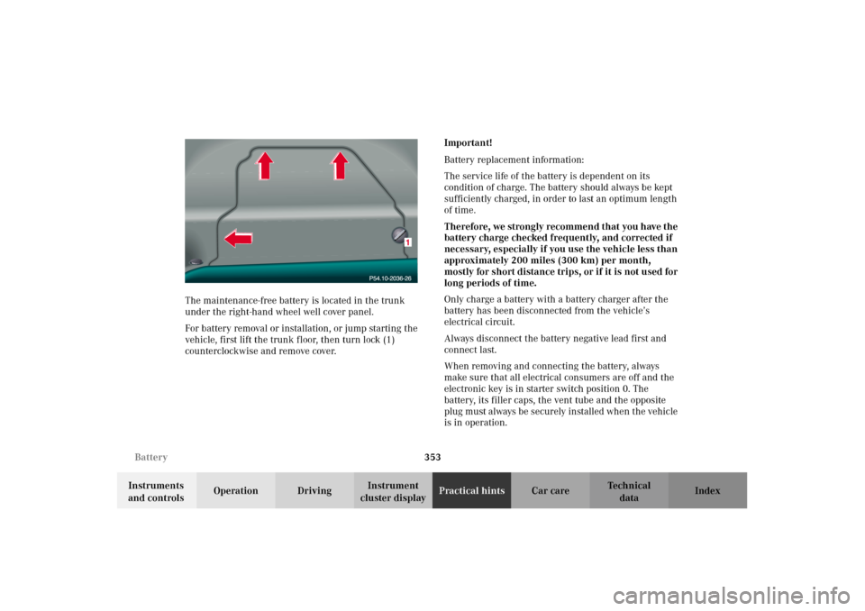
cluster displayPractical hintsCar care Index The maintenance-free battery is located in the trunk
under the right-hand wheel well cover panel.
For battery removal or installation, or jump starting the
vehicle, first lift the trunk floor, then turn lock (1)
counterclockwise and remove cover.Important!
Battery replacement information:
The service life of the battery is dependent on its
condition of charge. The battery should always be kept
sufficiently charged, in order to last an optimum length
of time.
Therefore, we strongly recommend that you have the
battery charge checked frequently, and corrected if
necessary, especially if you use the vehicle less than
approximately 200 miles (300 km) per month,
mostly for short distance trips, or if it is not used for
long periods of time.
Only charge a battery with a battery charger after the
battery has been disconnected from the vehicle’s
electrical circuit.
Always disconnect the battery negative lead first and
connect last.
When removing and connecting the battery, always
make sure that all electrical consumers are off and the
electronic key is in starter switch position 0. The
battery, its filler caps, the vent tube and the opposite
plug must always be securely installed when the vehicle
is in operation.
J_OM_215.book Seite 353 Mittwoch, 30. Mai 2001 2:01 14
Page 362 of 430
359 Towing the vehicle
Te ch n i c a l
data Instruments
and controlsOperation DrivingInstrument
cluster displayPractical hintsCar care Index We recommend that the vehicle be transported using
flat bed equipment. This method is preferable to other
types of towing.
Important!
To prevent damage during transport, do not tie down
vehicle by its chassis or suspension parts.
The vehicle may be towed with all wheels on the ground
and the selector lever in position “N” for distances up to
30 miles (50 km) and at a speed not to exceed 30 mph
(50 km/h). The electronic key must be in starter switch
position 2.
To be certain to avoid a possibility of damage to the
transmission, however, we recommend the drive shaft
be disconnected at the rear axle drive flange for any
towing beyond a short tow to a nearby garage.
Do not tow with sling-type equipment. Towing with
sling-type equipment over bumpy roads will damage
radiator and supports.
Use wheel lift, dolly, or flat bed equipment, with
electronic key in starter switch turned to position 0.Note:
To signal turns while being towed with hazard warning
flasher in use, turn electronic key in starter switch to
position 2 and activate combination switch for left or
right turn signal in usual manner – only the selected
turn signal will operate.
Upon canceling the turn signal, the hazard warning
flasher will operate again.
Caution!
If the vehicle is towed with the front axle raised, the
engine must be shut off (electronic key in starter switch
position 0 or 1). Otherwise, the ESP will immediately be
engaged and will apply the rear wheel brakes.
Switch off the tow-away alarm (see page 64) and the
automatic central locking, see individual setting menu
“VEHICLE” – “AUTOMATIC DOOR LOCK” on page 144.
Wa r n i n g !
With the engine not running, there is no power
assistance for the braking and steering systems. In
this case, it is important to keep in mind that a
considerably higher degree of effort is necessary to
brake and steer the vehicle.
J_OM_215.book Seite 359 Mittwoch, 30. Mai 2001 2:01 14
Page 371 of 430
368 Exterior lamps
Te ch n i c a l
data Instruments
and controlsOperation DrivingInstrument
cluster displayPractical hintsCar care Index
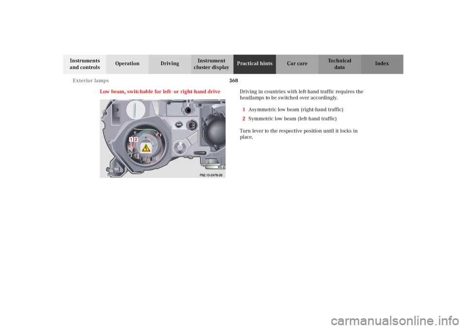
Low beam, switchable for left- or right-hand driveDriving in countries with left-hand traffic requires the
headlamps to be switched over accordingly.
1Asymmetric low beam (right-hand traffic)
2Symmetric low beam (left-hand traffic)
Turn lever to the respective position until it locks in
place.
J_OM_215.book Seite 368 Mittwoch, 30. Mai 2001 2:01 14
Page 397 of 430

394 Technical data
Te ch n i c a l
data Instruments
and controlsOperation DrivingInstrument
cluster displayPractical hints Car care Index
Te ch n i c a l d a t a
Model CL 500 (215.375
1)CL 55 AMG (215.373
1)CL 600 (215.378
1)
Engine 113 113 137
Mode of operation 4-stroke engine,
gasoline injection4-stroke engine,
gasoline injection4-stroke engine,
gasoline injection
No. of cylinders8812
Bore 3.82 in (97.00 mm) 3.82 in (97.00 mm) 3.31 in (84.00 mm)
Stroke 3.31 in (84.00 mm) 3.60 in (92.00 mm) 3.43 in (87.00 mm)
Total piston displacement 303.5 cu.in. (4966 cm
3) 332.0 cu.in. (5439 cm
3) 353.6 cu.in. (5786 cm
3)
Compression ratio 10:1 10.5:1 10:1
Output acc.
to SAE J 1349302 hp/5500 rpm
(225 kW/5500 rpm)355 hp/5500 rpm
(265 kW/5500 rpm)362 hp/5500 rpm
(270 kW/5500 rpm)
Maximum torque acc.
to SAE J 1349339 ft-lb/2700 rpm
(460 Nm/2700 rpm)390 ft.lb/3150 rpm
(530 Nm/3150 rpm)391 ft-lb/4100 rpm
(530 Nm/4100 rpm)
Maximum engine speed 6000 rpm 6000 rpm 6000 rpm
Firing order 1-5-4-2-6-3-7-8 1-5-4-2-6-3-7-8 1-12-5-8-3-10-6-7-2-11-4-9
Poly-V-belt 2390 mm 2390 mm 2335 mm
1 The quoted data apply only to the standard vehicle. See an authorized Mercedes-Benz Center for the
corresponding data of all special bodies and special equipment.
J_OM_215.book Seite 394 Mittwoch, 30. Mai 2001 2:01 14
Page 402 of 430

399 Fuels, coolants, lubricants etc. - capacities
Te ch n i c a l
data Instruments
and controlsOperation DrivingInstrument
cluster displayPractical hints Car care Index Fuels, coolants, lubricants etc. - capacities
Vehicle components and their respective lubricants must match. Therefore use only brands tested and recommended
by us. Please refer to the Factory Approved Service Products pamphlet, or inquire at your Mercedes-Benz Center.
Model Capacity Fuels, coolants, lubricants etc.
Engine with oil filter CL 500
CL 55 AMG
CL 6008.5 US qt (8.0 l)
8.0 US qt (7.5 l)
10.0 US qt (9.5 l)Recommended engine oils
Automatic transmission 9.6 US qt (9.1 l) Automatic transmission fluid
Rear axle 1.7 US qt (1.6 l) Hypoid gear oil SAE 85 W 90
Hydraulic system for
active body control (ABC)approx. 5.3 US qt (5.0 l) MB Hydraulic fluid
Power steering approx. 1.1 US qt (1.0 l) MB Power steering fluid
Front wheel hubs approx. 2.1 oz (60 g) each High temperature roller bearing grease
Brake system 0.7 US qt (0.7 l) MB Brake fluid (DOT 4+)
Cooling system CL 500
CL 55 AMG
CL 600approx. 12.1 US qt (11.5 l)
approx. 12.1 US qt (11.5 l)
approx. 12.7 US qt (12.0 l)MB Anticorrosion/antifreeze
J_OM_215.book Seite 399 Mittwoch, 30. Mai 2001 2:01 14
Page 406 of 430
403 Fuels, coolants, lubricants etc. - capacities
Te ch n i c a l
data Instruments
and controlsOperation DrivingInstrument
cluster displayPractical hints Car care Index Gasoline additives
A major concern among engine manufacturers is carbon
build up caused by gasoline. Mercedes-Benz
recommends the use of only quality gasoline containing
additives that prevent the build up of carbon deposits.
After an extended period of using fuels without such
ad ditives , car bon d ep osits c an bui ld up esp eci ally on t he
intake valves and in the combustion area, leading to
engine performance problems such as:
•warm-up hesitation,
•unstable idle,
•knocking/pinging,
•misfire,
•power loss.
Do not blend other specific fuel additives with fuel.
They only result in unnecessary cost, and may be
harmful to the engine operation.
Damage or malfunctions resulting from poor fuel
quality or from blending specific fuel additives are not
covered by the Mercedes-Benz Limited Warranty.Coolants
The engine coolant is a mixture of water and
anticorrosion/antifreeze, which provides:
•corrosion protection,
•freeze protection,
•boiling protection (by increasing the boiling point).
The cooling system was filled at the factory with a
coolant providing freeze protection to approximately
-22
°F (-30
°C) and corrosion protection.
If the antifreeze mixture is effective to -22
°F (-30
°C), the
boiling point of the coolant in the pressurized cooling
system is reached at approximately 266
°F (130
°C).
The coolant solution must be used year round to provide
the necessary corrosion protection and increase in the
boil-over protection. You should have it replaced every
3years.
To provide the important corrosion protection, the
solution must be at least 45% anticorrosion/antifreeze
(equals a freeze protection to approx. - 22
°F [-30
°C]). If
you use a solution that is more than 55% anticorrosion/
antifreeze (freeze protection to approx. - 49
°F [-45
°C]),
J_OM_215.book Seite 403 Mittwoch, 30. Mai 2001 2:01 14
Page 409 of 430
406 Consumer information
Te ch n i c a l
data Instruments
and controlsOperation DrivingInstrument
cluster displayPractical hints Car care Index
Tempera t u re
The temperature grades are A (the highest), B, and C,
representing the tire’s resistance to the generation of
heat and its ability to dissipate heat when tested under
controlled conditions on a specified indoor laboratory
test wheel. Sustained high temperature can cause the
material of the tire to degenerate and reduce tire life,
and excessive temperature can lead to sudden tire
failure. The grade C corresponds to a level of
performance which all passenger car tires must meet
under the Federal Motor Vehicle Safety Standard
No. 109. Grades B and A represent higher levels of
performance on the laboratory test wheel than the
minimum required by law.
Wa r n i n g !
The temperature grade for this tire is established
for a tire that is properly inflated and not
overloaded. Excessive speed, underinflation, or
excessive loading, either separately or in
combination, can cause excessive heat build up
and possible tire failure.
J_OM_215.book Seite 406 Mittwoch, 30. Mai 2001 2:01 14
Page 413 of 430
410 Index
Te ch n i c a l
data Instruments
and controlsOperation DrivingInstrument
cluster displayPractical hints Car careIndex
DDashboard ......................................................................... 22
Deep water
Driving instructions ................................................. 254
DISPLAY DEFECTIVE (engine control unit) -
malfunction and warning messages ......................304
DISPLAY DEFECTIVE (several systems) -
malfunction and warning messages ......................304
Display illumination .......................................................116
Distronic (DTR) ...................................................... 135, 259
Activation of Distronic ............................................. 262
Additional driving hints .......................................... 267
Cleaning sensor ........................................................ 384
Deactivation of Distronic .........................................264
Displays in the speedometer dial ........................... 274
Distance warning function ...................................... 270
Distronic settings ...................................................... 271
Driving with Distronic activated ............................265
Invalid attempts to activate ..................................... 263
Multifunction display ...............................................273
Warning lamp ............................................................ 301
DISTRONIC (DTR) -
malfunction and warning messages ......................327
DOOR -
malfunction and warning messages ......................322Door control panel ........................................................... 20
Door entry lamps ........................................................... 190
Doors ..................................................................................47
Power closing assist .................................................... 49
Drinking and driving .................................................... 245
Drive sensibly - save fuel ............................................. 245
Driving instructions ..................................................... 245
Driving off ...................................................................... 247
EEasy-entry/exit feature ...................................................66
ELEC. STABIL. PROGR. -
malfunction and warning messages ..................... 309
Electronic key ................................................................... 29
Changing batteries .................................................. 369
Starting the engine .................................................. 233
Turning off the engine ............................................ 233
Electronic main key
Synchronizing remote control ................................ 371
Electronic stability program (ESP) ............................. 278
Warning lamp ............................................................301
Emergency call
See Tele Aid ............................................................... 216
Emergency engine shut-down ...................................... 374
J_OM_215.book Seite 410 Mittwoch, 30. Mai 2001 2:01 14