2002 MERCEDES-BENZ CL55AMG ECU
[x] Cancel search: ECUPage 241 of 430
238 Automatic transmission
Te ch n i c a l
data Instruments
and controlsOperationDrivingInstrument
cluster displayPractical hints Car care Index
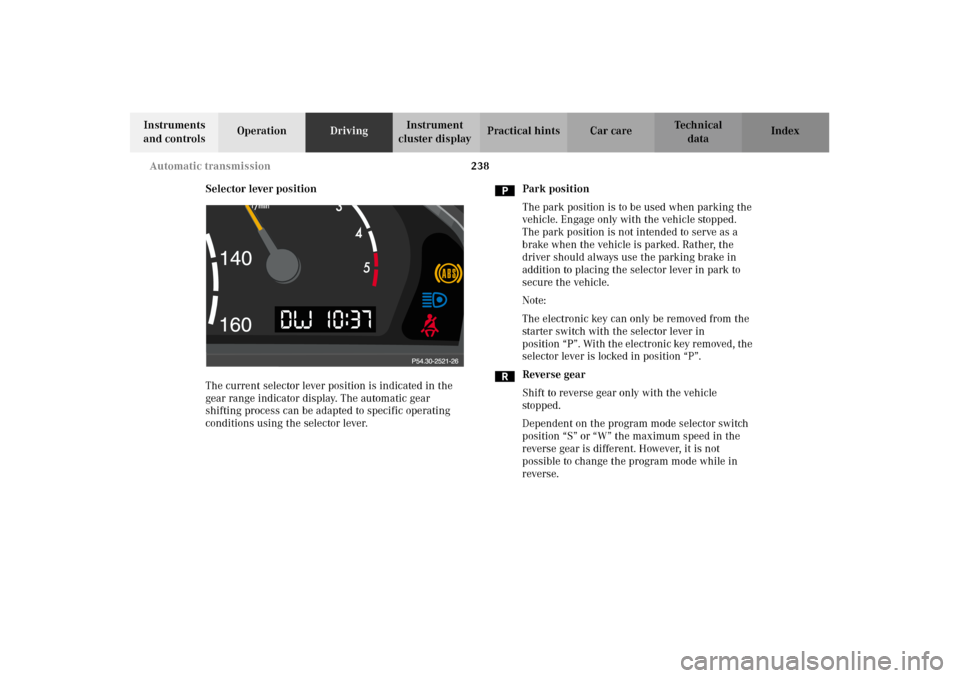
Selector lever position
The current selector lever position is indicated in the
gear range indicator display. The automatic gear
shifting process can be adapted to specific operating
conditions using the selector lever.Park position
The park position is to be used when parking the
vehicle. Engage only with the vehicle stopped.
The park position is not intended to serve as a
brake when the vehicle is parked. Rather, the
driver should always use the parking brake in
addition to placing the selector lever in park to
secure the vehicle.
Note:
The electronic key can only be removed from the
starter switch with the selector lever in
position “P”. With the electronic key removed, the
selector lever is locked in position “P”.
Reverse gear
Shift to reverse gear only with the vehicle
stopped.
Dependent on the program mode selector switch
position “S” or “W” the maximum speed in the
reverse gear is different. However, it is not
possible to change the program mode while in
reverse.
J_OM_215.book Seite 238 Mittwoch, 30. Mai 2001 2:01 14
Page 257 of 430
254 Driving instructions
Te ch n i c a l
data Instruments
and controlsOperationDrivingInstrument
cluster displayPractical hints Car care Index
Deep water
Caution!
Do not drive through f looded areas or water of unknown
depth.
If you must drive through deep water, drive slowly to
prevent water from entering the engine compartment or
passenger compartment, being ingested by the air
intake, possibly causing damage to electrical
components or wiring, to engine or transmission that is
not covered by the Mercedes-Benz Limited Warranty.Passenger compartment
Wa r n i n g !
Always fasten items being carried as securely as
possible.In an accident, during hard braking or sudden
maneuvers, loose items will be thrown around
inside the vehicle, and cause injury to vehicle
oc cu pa nt s u nl ess t he i tem s are s ecurely fastened i n
the vehicle.The trunk is the preferred place to carry objects.
J_OM_215.book Seite 254 Mittwoch, 30. Mai 2001 2:01 14
Page 300 of 430
297 Malfunction and indicator lamps
Te ch n i c a l
data Instruments
and controlsOperation DrivingInstrument
cluster displayPractical hints Car care Index may still drive the vehicle, however, in all cases, we
recommend that you have the system checked at your
authorized Mercedes-Benz Center as soon as possible.
If the “CHECK ENGINE” lamp comes on continuously
and /or the vehicle is not driving normally (e.g.
malfunction of the fuel management system or running
out of fuel), serious damage can occur to the emission
system. Please contact your authorized Mercedes-Benz
Center immediately.
The Sequential Multiport Fuel Injection (SFI) control
module monitors emission control components that
either provide input signals to or receive output signals
from the control module. Malfunctions resulting from
interruptions or failure of any of these components are
indicated by the “CHECK ENGINE” malfunction
indicator lamp in the instrument cluster and are
simultaneously stored in the SFI control module.
If the “CHECK ENGINE” malfunction indicator lamp
comes on, have the system checked at your authorized
Mercedes-Benz Center as soon as possible.With some exceptions, the control module switches off
the “CHECK ENGINE” malfunction indicator lamp if the
condition, causing the lamp to come on, no longer exists
during three consecutive cycles.
An on-board diagnostic connector is located in the
passenger compartment near to the parking brake
pedal, allowing the accurate identification of system
malfunctions through the readout of diagnostic trouble
codes.
Notes:
When running out of fuel, the “CHECK ENGINE”
malfunction indicator lamp comes on and the engine
possibly switches to its limp-home (emergency
operation) mode.
To cancel the limp-home mode, the engine may have to
be started three or four times after refueling. The
malfunction indicator lamp remains illuminated. Have
the system checked at your authorized Mercedes-Benz
Center immediately.
J_OM_215.book Seite 297 Mittwoch, 30. Mai 2001 2:01 14
Page 344 of 430

341 Spare wheel
Te ch n i c a l
data Instruments
and controlsOperation DrivingInstrument
cluster displayPractical hintsCar care Index Spare wheel, vehicle tools, storage compartment
1Jack
2Luggage bowl with vehicle tool kit, towing eye bolt,
fuses, fuse extractor and fuse chart
3Storage tray
4Spare wheel Lift trunk floor and engage handle in upper edge of
trunk.
Always lower trunk floor before closing trunk lid.
To remove the spare wheel:
Take out the vehicle tool kit tray.
Turn t he luggage b owl coun ter clock wise an d re move t he
spare wheel.
To store spare wheel:
Place spare wheel in wheel well and secure it with
luggage bowl. Turn luggage bowl clockwise to its stop.
Place vehicle tool kit tray in luggage bowl.
P40.10-0523-26
1
4
3
2
J_OM_215.book Seite 341 Mittwoch, 30. Mai 2001 2:01 14
Page 356 of 430
353 Battery
Te ch n i c a l
data Instruments
and controlsOperation DrivingInstrument
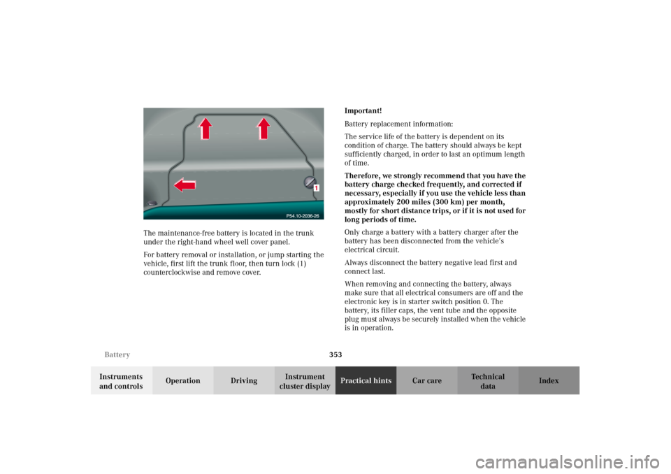
cluster displayPractical hintsCar care Index The maintenance-free battery is located in the trunk
under the right-hand wheel well cover panel.
For battery removal or installation, or jump starting the
vehicle, first lift the trunk floor, then turn lock (1)
counterclockwise and remove cover.Important!
Battery replacement information:
The service life of the battery is dependent on its
condition of charge. The battery should always be kept
sufficiently charged, in order to last an optimum length
of time.
Therefore, we strongly recommend that you have the
battery charge checked frequently, and corrected if
necessary, especially if you use the vehicle less than
approximately 200 miles (300 km) per month,
mostly for short distance trips, or if it is not used for
long periods of time.
Only charge a battery with a battery charger after the
battery has been disconnected from the vehicle’s
electrical circuit.
Always disconnect the battery negative lead first and
connect last.
When removing and connecting the battery, always
make sure that all electrical consumers are off and the
electronic key is in starter switch position 0. The
battery, its filler caps, the vent tube and the opposite
plug must always be securely installed when the vehicle
is in operation.
J_OM_215.book Seite 353 Mittwoch, 30. Mai 2001 2:01 14
Page 367 of 430
364 Exterior lamps
Te ch n i c a l
data Instruments
and controlsOperation DrivingInstrument
cluster displayPractical hintsCar care Index
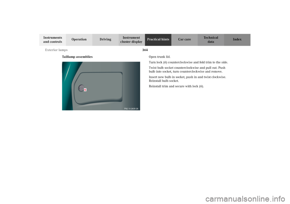
Taillamp assembliesOpen trunk lid.
Turn lock (6) counterclockwise and fold trim to the side.
Twist bulb socket counterclockwise and pull out. Push
bulb into socket, turn counterclockwise and remove.
Insert new bulb in socket, push in and twist clockwise.
Reinstall bulb socket.
Reinstall trim and secure with lock (6).
P82.10-2635-26
6
J_OM_215.book Seite 364 Mittwoch, 30. Mai 2001 2:01 14
Page 369 of 430

366 Exterior lamps
Te ch n i c a l
data Instruments
and controlsOperation DrivingInstrument
cluster displayPractical hintsCar care Index
License plate lamp
Loosen both securing screws (1), remove lamp and
replace tubular lamp (C 5 W/4 cp).Side marker lamp, front (5 W/4 cp bulb)
Carefully slide lamp towards rear (arrow 1), and remove
front end first (arrow 2).
Twist bulb socket counterclockwise and pull out.
Remove bulb from socket.
Insert new bulb in socket. Reinstall bulb socket, push in
and twist clockwise.
To reinstall lamp, set rear end of lamp in bumper and let
front end snap into place.
P82.10-2634-26
2
1
J_OM_215.book Seite 366 Mittwoch, 30. Mai 2001 2:01 14
Page 419 of 430

416 Index
Te ch n i c a l
data Instruments
and controlsOperation DrivingInstrument
cluster displayPractical hints Car careIndex
NNavigation system .......................................................... 134
Night security illumination ......................................... 162OOn-board diagnostic system .........................................296
Operator’s Manual ............................................................. 8
Outside temperature indicator .....................................117
Overhead control panel ................................................... 21PPanic button ...................................................................... 46
Parcel net in front passenger footwell ....................... 206
Parcel net in trunk ........................................................ 205
Parking ............................................................................ 248
Parking assist (Parktronic) .......................................... 286
Parking brake ............................. 202, 244, 248, 298, 346
PA R K I N G B R A K E -
malfunction and warning messages ......................308
Power assistance ............................................................246
Power closing assist
Doors and trunk lid .................................................... 49Power head restraints, rear ............................................ 81
Power seats, front
Backrest ........................................................................ 72
Seat ventilation system .............................................. 79
Power windows ............................................................... 183
Blocking of rear side window operation ................ 185
Express opening and closing .................................. 184
Opening and closing ...................................................44
Synchronizing ........................................................... 185
Problems with your vehicle ............................................ 14
Product information .......................................................... 7
RRadio
See Audio systems .................................................... 126
Radio - see Audio systems ............................................ 126
Radio transmitters ......................................................... 214
Rain sensor
See intermittent wiping ........................................... 165
Rear passenger compartment
adjustable air outlets ................................................ 182
Rear view mirror
Inside, automatic antiglare ...................................... 106
J_OM_215.book Seite 416 Mittwoch, 30. Mai 2001 2:01 14