Page 286 of 430
283 Driving systems
Te ch n i c a l
data Instruments
and controlsOperationDrivingInstrument
cluster displayPractical hints Car care Index Level control system
The switch is located on the center console.
Press the switch when the engine is running:
1Raise vehicle chassis
2Lower vehicle chassis
3Indicator lamp
4Indicator lampThe vehicle chassis ride height is raised or lowered
automatically according to the selected setting and to
the vehicle speed. This helps to increase vehicle
handling safety and lowers fuel consumption.
The selected setting is stored in memory, even with the
electronic key removed from the starter switch.
Note:
See “ACTIVE BODY CONTROL” on page 316 for
malfunction and warning messages.
Wa r n i n g !
To help avoid personal injury, keep hands and feet
away from wheel housing area, and stay away from
under the vehicle when lowering the vehicle
chassis.
J_OM_215.book Seite 283 Mittwoch, 30. Mai 2001 2:01 14
Page 287 of 430
284 Driving systems
Te ch n i c a l
data Instruments
and controlsOperationDrivingInstrument
cluster displayPractical hints Car care Index
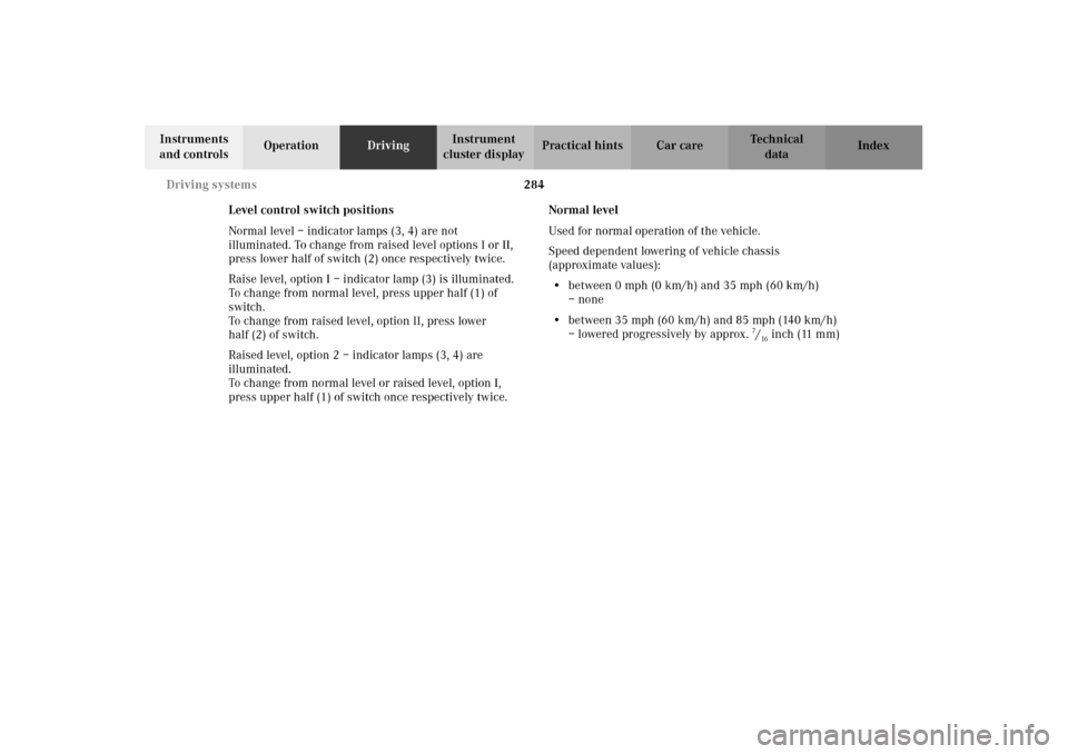
Level control switch positions
Normal level – indicator lamps (3, 4) are not
illuminated. To change from raised level options I or II,
press lower half of switch (2) once respectively twice.
Raise level, option I – indicator lamp (3) is illuminated.
To change from normal level, press upper half (1) of
switch.
To change from raised level, option II, press lower
half (2) of switch.
Raised level, option 2 – indicator lamps (3, 4) are
illuminated.
To change from normal level or raised level, option I,
press upper half (1) of switch once respectively twice.Normal level
Used for normal operation of the vehicle.
Speed dependent lowering of vehicle chassis
(approximate values):
•between 0 mph (0 km/h) and 35 mph (60 km/h)
– none
•between 35 mph (60 km/h) and 85 mph (140 km/h)
– lowered progressively by approx. 7/16inch (11 mm)
J_OM_215.book Seite 284 Mittwoch, 30. Mai 2001 2:01 14
Page 288 of 430
285 Driving systems
Te ch n i c a l
data Instruments
and controlsOperationDrivingInstrument
cluster displayPractical hints Car care Index Raised level, option I
This setting should be used when road surface
conditions are rough and must be used when driving
with snow chains mounted.
Important!
Driving with snow chains requires increased space
between tire and wheel housing. Refer to page 251 for
driving with snow chains.
Speed dependent lowering of vehicle chassis
(approximate values):
•at standstill – raised by approx. one half inch
(14 mm)
•between 35 mph (60 km/h) and 100 mph
(160 km/h) – lowered progressively by approx.
one half inch (14 mm)Raised level, option II
This setting should be used when road surface
conditions are very rough for increased ground
clearance.
Speed dependent lowering of vehicle chassis
(approximate values):
•at standstill - raised by approx. one inch (24 mm)
•between 0 mph (0 km/h) and 35 mph (6o km/h) -
lowered progressively by approx. 3/8inch (10 mm)
•between 35 mph (60 km/h) and 100 mph
(160 km/h) – lowered progressively by additional
approx. one half inch (14 mm)
J_OM_215.book Seite 285 Mittwoch, 30. Mai 2001 2:01 14
Page 320 of 430
317 Malfunction and warning messages
Te ch n i c a l
data Instruments
and controlsOperation DrivingInstrument
cluster displayPractical hints Car care Index
3 The ABC is defective. Stop the vehicle.
Press upper half of level control switch, see page 283
- system selects raised level mode.
The vehicle chassis is raised depending on the kind of defect.Important!
The wheels may not have sufficient clearance when the
steering wheel is turned beyond a certain angle if the
“ACTIVE BODY CONTROL – STOP, CAR TOO LOW!”
message appears. The front fenders will be damaged if
the steering wheel is turned too far. Watch and listen for
scraping noises.
Do not exceed a speed of 50 mph (80 km/h).
Visit your Mercedes-Benz Center as soon as possible.
4 The capability of the system is restricted.Important!
When the message “ACTIVE BODY CONTROL – VISIT
WORKSHOP!” appears, do not exceed a speed of 50 mph
(80 km/h). Visit your Mercedes-Benz Center as soon as
possible.
J_OM_215.book Seite 317 Mittwoch, 30. Mai 2001 2:01 14
Page 360 of 430
357 Towing the vehicle
Te ch n i c a l
data Instruments
and controlsOperation DrivingInstrument
cluster displayPractical hintsCar care Index Towing the vehicleImportant!
When towing the vehicle, please, note the following:
With the automatic central locking activated and the
electronic key in starter switch position 2 (vehicles with
KEYLESS-GO: in “On” position, see page 230), the
vehicle doors lock if the left front wheel as well as the
right rear wheel are turning at vehicle speeds of approx.
9 mph (15 km/h) or more.
To prevent the vehicle door locks from locking,
deactivate the automatic central locking.This can be
adjusted in the individual setting menu “VEHICLE” –
“AUTOMATIC DOOR LOCK”. See page 144.
Towing of the vehicle should only be done using the
properly installed towing eye bolt. Never attach tow
cable, tow rope or tow rod to vehicle chassis, frame
or suspension parts.
Note:
The selector lever will remain locked in position “P” and
the electronic key cannot be turned in the starter switch
if the battery is disconnected or discharged. See battery
on page 352 or jump starting on page 355.
Wa r n i n g !
Prior to towing the vehicle with all wheels on the
ground, make certain that the electronic key is in
starter switch position 2.If the electronic key is left in the starter switch
position 0 for an extended period of time, it can no
longer be turned in the switch. In this case, the
steering is locked. To unlock, remove electronic key
from starter switch and reinsert.
J_OM_215.book Seite 357 Mittwoch, 30. Mai 2001 2:01 14
Page 362 of 430
359 Towing the vehicle
Te ch n i c a l
data Instruments
and controlsOperation DrivingInstrument
cluster displayPractical hintsCar care Index We recommend that the vehicle be transported using
flat bed equipment. This method is preferable to other
types of towing.
Important!
To prevent damage during transport, do not tie down
vehicle by its chassis or suspension parts.
The vehicle may be towed with all wheels on the ground
and the selector lever in position “N” for distances up to
30 miles (50 km) and at a speed not to exceed 30 mph
(50 km/h). The electronic key must be in starter switch
position 2.
To be certain to avoid a possibility of damage to the
transmission, however, we recommend the drive shaft
be disconnected at the rear axle drive flange for any
towing beyond a short tow to a nearby garage.
Do not tow with sling-type equipment. Towing with
sling-type equipment over bumpy roads will damage
radiator and supports.
Use wheel lift, dolly, or flat bed equipment, with
electronic key in starter switch turned to position 0.Note:
To signal turns while being towed with hazard warning
flasher in use, turn electronic key in starter switch to
position 2 and activate combination switch for left or
right turn signal in usual manner – only the selected
turn signal will operate.
Upon canceling the turn signal, the hazard warning
flasher will operate again.
Caution!
If the vehicle is towed with the front axle raised, the
engine must be shut off (electronic key in starter switch
position 0 or 1). Otherwise, the ESP will immediately be
engaged and will apply the rear wheel brakes.
Switch off the tow-away alarm (see page 64) and the
automatic central locking, see individual setting menu
“VEHICLE” – “AUTOMATIC DOOR LOCK” on page 144.
Wa r n i n g !
With the engine not running, there is no power
assistance for the braking and steering systems. In
this case, it is important to keep in mind that a
considerably higher degree of effort is necessary to
brake and steer the vehicle.
J_OM_215.book Seite 359 Mittwoch, 30. Mai 2001 2:01 14