2002 MERCEDES-BENZ CL500 key battery
[x] Cancel search: key batteryPage 232 of 430
229 Starter switch
Te ch n i c a l
data Instruments
and controlsOperationDrivingInstrument
cluster displayPractical hints Car care Index Important!
If the electronic key is left in the starter switch
position 0 for an extended period of time, it can no
longer be turned in the lock. In this case, remove
electronic key from starter switch and reinsert.
Caution!
To prevent accelerated battery discharge and a possible
dead battery, always remove the electronic key from the
starter switch. Do not leave the electronic key in starter
switch position 0.Notes:
A warning sounds when the driver’s door is opened
with the electronic key in starter switch position 1 or 0.
If the electronic key cannot be turned in the starter
switch, the vehicle battery may not be sufficiently
charged. See battery on page 352 or jump starting on
page 355.
With the engine at idle speed, the charging rate of the
alternator (output) is limited.
It is therefore recommended that you turn off
unnecessary electrical consumers while driving in stop-
and-go traffic. This precaution helps to avoid draining of
the battery.
Unnecessary strain on the battery and charging system
may be minimized by turning off the following power
consumers, for example:
Heated seats, rear window defroster. In addition, the
automatic climate air volume control should be set to
the lowest position.
J_OM_215.book Seite 229 Mittwoch, 30. Mai 2001 2:01 14
Page 234 of 430
231 Starter switch — KEYLESS-GO
Te ch n i c a l
data Instruments
and controlsOperationDrivingInstrument
cluster displayPractical hints Car care Index “On” position (starter switch position 1, see page 228).
Most electrical consumers can be operated. For detailed
information see respective subjects.
Operation / driving position (starter switch position 2,
see page 228).
All electrical consumers can be operated. Gear selector
is unlocked.
“Off” position (electronic key removable from starter
switch).
Most electrical consumers cannot be operated.
The selector lever is locked in position “P”.
Notes:
For improved recognition of the KEYLESS-GO-card the
doors should be closed when pressing the start-/stop
button.
The gear selector lever can only be moved with the
vehicle battery charged and connected, and the starter
switch in the Operation position. With the gear selector
lever in position “P”, the brake pedal must also be
depressed.Important!
For the KEYLESS-GO-system to function properly, the
operator should observe the following:
•If the KEYLESS-GO-card is positioned farther away
from the vehicle (e.g. inside clothing or a briefcase),
the vehicle cannot be locked (see page 39) or started
with the start-/stop button (see page 234).
•If the KEYLESS-GO-card is removed from the vehicle
while the engine is running and a door opened, or
by placing the card in front of the center armrest
(see page 195), the message “CHIP-CARD – NOT
RECOGNIZED!” will appear intermittent in the
multifunction display, see page 37.
J_OM_215.book Seite 231 Mittwoch, 30. Mai 2001 2:01 14
Page 235 of 430
232 Starter switch — KEYLESS-GO
Te ch n i c a l
data Instruments
and controlsOperationDrivingInstrument
cluster displayPractical hints Car care Index
•Do not forget, the engine can be started by anyone if
a KEYLESS-GO-card is left inside the vehicle.
•To be able to operate the vehicle in the case of a
malfunction in the KEYLESS-GO-system (e.g. strong
radio frequency disturbance), we recommend that
you carry the electronic key plus mechanical key
with you and keep them in a safe place so that they
are always handy. Never leave the electronic key in
the vehicle.
•To avoid radio transmission interference, never store
the KEYLESS-GO-card together with other electronic
items (e.g. cellular telephones, other KEYLESS-GO-
cards) or metallic objects (e.g. coins, metal foil).Notes:
With the engine at idle speed, the charging rate of the
alternator (output) is limited.
It is therefore recommended that you turn off
unnecessary electrical consumers while driving in stop-
and-go traffic. This precaution helps to avoid draining of
the battery.
Unnecessary strain on the battery and charging system
may be minimized by turning off the following power
consumers, for example:
Heated seats, rear window defroster. In addition, the
automatic climate air volume control should be set to
the lowest position.
J_OM_215.book Seite 232 Mittwoch, 30. Mai 2001 2:01 14
Page 282 of 430
279 Driving systems
Te ch n i c a l
data Instruments
and controlsOperationDrivingInstrument
cluster displayPractical hints Car care Index Notes:
The yellow ESP warning lampv in the speedometer
dial comes on with the electronic key in starter switch
position 2. It should go out with the engine running.
If the ESP warning message is displayed, a malfunction
has been detected in the system. Only partial engine
output will be available.
Have the ESP checked at your authorized
Mercedes-Benz Center as soon as possible.
For ESP warning message, see page 309.
With the ABS malfunctioning, the ESP and the BAS is
also switched off.
Driving the vehicle with varied size tires will cause the
wheels to rotate at different speeds, therefore the ESP
may activate (yellow ESP warning lamp in speedometer
d ial com es on ). For t his reas on, all wheels, in cludin g t he
spare wheel, must have the same tire size. When testing the parking brake on a brake test
dynamometer, the engine must be shut off. Otherwise,
the ESP will immediately be engaged and will apply the
rear wheel brakes.
In winter operation, the maximum effectiveness of the
ESP is only achieved with Mercedes-Benz recommended
M+S rated radial-ply tires and/or snow chains.
Synchronizing ESP
If the power supply was interrupted (battery
disconnected or empty), the ESP warning message may
be displayed with the engine running.
Turn steering wheel completely to the left and then to
the right. The ESP warning message should go out.
J_OM_215.book Seite 279 Mittwoch, 30. Mai 2001 2:01 14
Page 298 of 430

295 Contents - Instrument cluster display
Te ch n i c a l
data Instruments
and controlsOperation DrivingInstrument
cluster displayPractical hints Car care Index
Instrument cluster displayMalfunction and indicator
lamps in the
instrument cluster ....................296
On-board
diagnostic system .......................296
Check engine malfunction
indicator lamp .............................296
Brake warning lamp ..................298
Supplemental
restraint system
(SRS) indicator lamp ..................299
Fuel reserve warning .................299
ABS malfunction
indicator lamp .............................300
Electronic stabilityprogram
(ESP) — warning lamp ............... 301
Distronic (DTR) —
warning lamp .............................. 301
Seat belt nonusage
warning lamp ..............................302Malfunction and indicator
lamp in the center console ...... 302
AIRBAG OFF indicator lamp .... 302
Malfunction and
warning messages in the
multifunction display .............. 303
DISPLAY DEFECTIVE
(engine control unit) ................. 304
DISPLAY DEFECTIVE
(several systems) ....................... 304
BATTERY /ALTERNATOR ......... 305
ENTRY POSITION ...................... 306
BRAKE ASSIST ........................... 306
BRAKE PAD WEAR .................... 307
BRAKE FLUID ............................ 307
PARKING BRAKE ....................... 308
TRUNK OPEN ............................. 308
ELEC. STABIL. PROG.
(Electronic stability program) . 309COOLANT (coolant level) .......... 310
COOLANT
(coolant temperature) .................311
LIGHTING SYSTEM .................... 312
LAMP SENSOR ........................... 314
SEAT BELT SYSTEM ................... 314
TELEPHONE – FUNCTION ....... 315
CRUISE CONTROL ..................... 315
ACTIVE BODY CONTROL
(ABC) ............................................ 316
TIRE PRESSURE ......................... 318
ENGINE OIL LEVEL ...................320
SEAT BACKREST ........................ 321
KEY ...............................................322
DOOR ...........................................322
HOOD ...........................................323
TELE AID .....................................323
WASHER FLUID .........................326
DISTRONIC (DTR) ......................327
J_OM_215.book Seite 295 Mittwoch, 30. Mai 2001 2:01 14
Page 327 of 430
324 Malfunction and warning messages
Te ch n i c a l
data Instruments
and controlsOperation DrivingInstrument
cluster displayPractical hints Car care Index
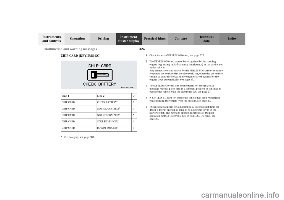
CHIP-CARD (KEYLESS-GO)
* C = Category, see page 303.1 Check battery of KEYLESS-GO-card, see page 372.
2 The KEYLESS-GO-card cannot be recognized by the running
engine (e.g. strong radio-frequency interference) or the card is not
in the vehicle.
Stop immediately and search for the KEYLESS-GO-card or continue
to operate the vehicle with the electron ic key, ot her wis e the vehic le
cannot be centrally locked or the engine started again after the
engine stops automatically. See page 37.
3 The KEYLESS-GO-card was momentarily not recognized. If
message repeats, place card in a different position or continue to
operate the vehicle with the electronic key, see page 37.
4 A KEYLESS-GO-card left inside the vehicle has been recognized
while locking the vehicle from the outside, see page 37.
5 The message appears for a maximum 60 seconds each time the
driver’s door is opened, as long as no electronic key is in the
starter switch. The message appears regardless of the past
operation method (electronic key or KEYLESS-GO-card), see
page 37. Line 1 Line 2 C*
CHIP CARD CHECK BATTERY!
1
2
CHIP CARD NOT RECOGNIZED!
2
1
CHIP CARD NOT RECOGNIZED!
3
2
CHIP CARD STILL IN VEHICLE!
4
1
CHIP CARD DO NOT FORGET!
5
1
J_OM_215.book Seite 324 Mittwoch, 30. Mai 2001 2:01 14
Page 332 of 430

329 Contents - Practical hints
Te ch n i c a l
data Instruments
and controlsOperation DrivingInstrument
cluster displayPractical hintsCar care Index
Practical hintsFirst aid kit .....................................330
Fuses ................................................ 331
Shelf below rear window ..............333
Hood .................................................334
Checking engine oil level .............337
Automatic transmission
fluid level ...................................338
Active body control
(ABC) fluid level ........................338
Coolant level ...................................339
Adding coolant ...........................339
Windshield and headlamp
washer system ...........................340
Windshield and headlamp
washer fluid mixing ratio .........340Spare wheel, vehicle tools, storage
compartment ............................. 341
Jack .................................................. 342
Wheels ............................................ 343
Tire Replacement ....................... 343
Rotating wheels ......................... 344
Spare wheel .................................... 344
Changing wheels ........................... 346
Tire inflation pressure ................. 351
Battery ............................................. 352
Jump starting ................................. 355
Towing the vehicle ........................ 357
Exterior lamps ............................... 360
Headlamp assembly .................. 361
Taillamp assemblies .................. 364
Standby bulb function .................. 367Changing batteries
in the electronic key .................369
Synchronizing
remote control ............................ 371
Changing batteries in
the KEYLESS-GO-card ..............372
Emergency engine shut-down ..... 374
Fuel filler flap,
manual release .......................... 374
Emergency operation of
sliding/pop-up roof ...................375
Replacing wiper blades ................. 376
Roof rack .........................................378
J_OM_215.book Seite 329 Mittwoch, 30. Mai 2001 2:01 14
Page 356 of 430
353 Battery
Te ch n i c a l
data Instruments
and controlsOperation DrivingInstrument
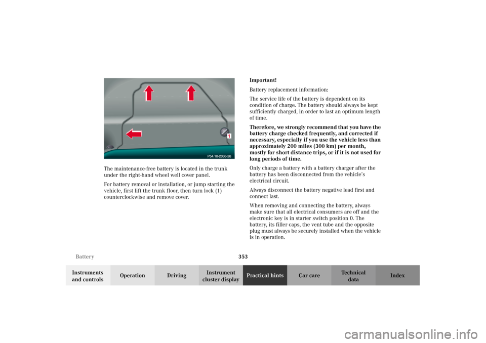
cluster displayPractical hintsCar care Index The maintenance-free battery is located in the trunk
under the right-hand wheel well cover panel.
For battery removal or installation, or jump starting the
vehicle, first lift the trunk floor, then turn lock (1)
counterclockwise and remove cover.Important!
Battery replacement information:
The service life of the battery is dependent on its
condition of charge. The battery should always be kept
sufficiently charged, in order to last an optimum length
of time.
Therefore, we strongly recommend that you have the
battery charge checked frequently, and corrected if
necessary, especially if you use the vehicle less than
approximately 200 miles (300 km) per month,
mostly for short distance trips, or if it is not used for
long periods of time.
Only charge a battery with a battery charger after the
battery has been disconnected from the vehicle’s
electrical circuit.
Always disconnect the battery negative lead first and
connect last.
When removing and connecting the battery, always
make sure that all electrical consumers are off and the
electronic key is in starter switch position 0. The
battery, its filler caps, the vent tube and the opposite
plug must always be securely installed when the vehicle
is in operation.
J_OM_215.book Seite 353 Mittwoch, 30. Mai 2001 2:01 14