Page 102 of 406

99 Instrument cluster
Te ch n i c a l
data Instruments
and controlsOperationDrivingInstrument
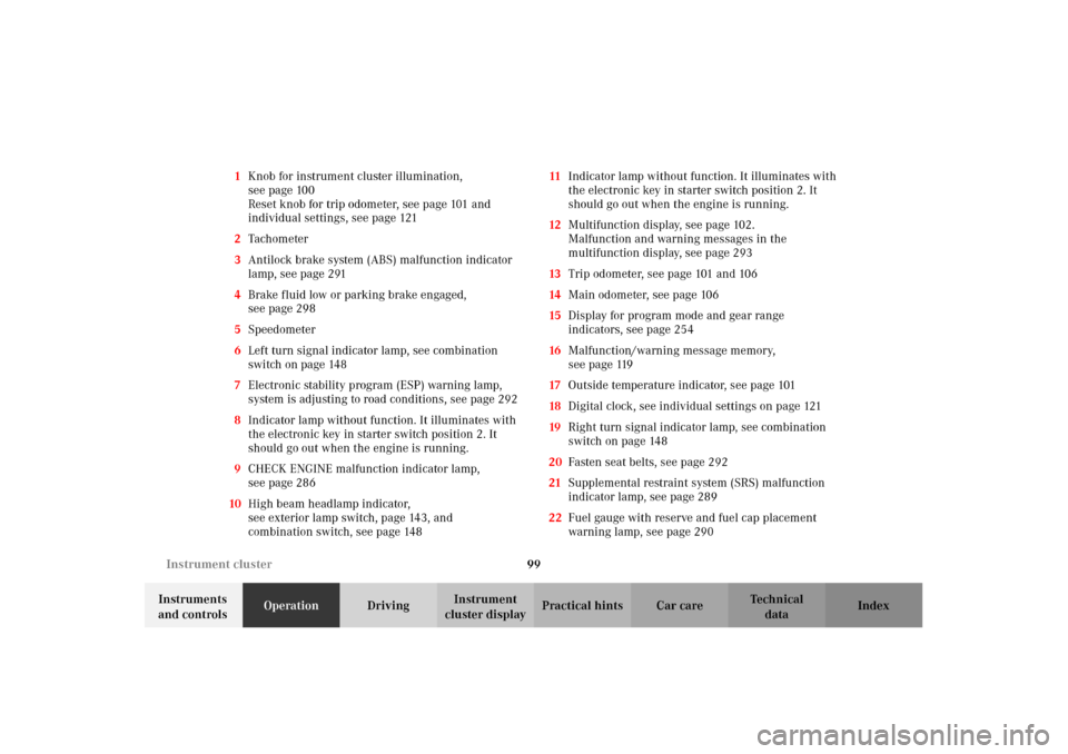
cluster displayPractical hints Car care Index 1Knob for instrument cluster illumination,
seepage100
Reset knob for trip odometer, see page 101 and
individual settings, see page 121
2Tachometer
3Antilock brake system (ABS) malfunction indicator
lamp, see page 291
4Brake fluid low or parking brake engaged,
seepage298
5Speedometer
6Left turn signal indicator lamp, see combination
switch on page 148
7Electronic stability program (ESP) warning lamp,
system is adjusting to road conditions, see page 292
8Indicator lamp without function. It illuminates with
the electronic key in starter switch position 2. It
should go out when the engine is running.
9CHECK ENGINE malfunction indicator lamp,
seepage286
10High beam headlamp indicator,
seeexterior lamp switch, page143, and
combination switch, see page 14811Indicator lamp without function. It illuminates with
the electronic key in starter switch position 2. It
should go out when the engine is running.
12Multifunction display, see page 102.
Malfunction and warning messages in the
multifunction display, see page 293
13Trip odometer, see page 101 and 106
14Main odometer, see page 106
15Display for program mode and gear range
indicators, see page 254
16Malfunction/warning message memory,
seepage119
17Outside temperature indicator, see page 101
18Digital clock, see individual settings on page 121
19Right turn signal indicator lamp, see combination
switch on page 148
20Fasten seat belts, see page 292
21Supplemental restraint system (SRS) malfunction
indicator lamp, see page 289
22Fuel gauge with reserve and fuel cap placement
warning lamp, see page 290
OM_203.book Seite 99 Donnerstag, 31. Mai 2001 11:57 11
Page 104 of 406

101 Instrument cluster
Te ch n i c a l
data Instruments
and controlsOperationDrivingInstrument
cluster displayPractical hints Car care Index Outside temperature indicator (17)
The temperature sensor is located in the front bumper
area. Due to its location, the sensor can be affected by
road or engine heat during idling or slow driving. This
means that the accuracy of the displayed temperature
can only be verified by comparison to a thermometer
placed next to the sensor, not by comparison to external
displays (e.g. bank signs etc.).
Adaption to ambient temperature takes place in steps
and depends on the prevailing driving conditions (stop-
and-go or moderate, constant driving) and amount of
temperature change.
Note:
The uni t for the temp erature in di cator d is play can b e set
in the individual setting menu “INSTRUMENT
CLUSTER” – “TEMP. INDICATOR” on page 121.Trip odometer (13)
To reset to “0” miles / km:
Activate the instrument cluster if it is not already
activated, see page 100.
Press button è or ÿ on the multifunction
steering wheel repeatedly until the trip odometer
appears if it is not displayed. See page 106.
Press button (1) on the instrument cluster, see page 100.
Tachometer (2)
The red marking on the tachometer denotes excessive
engine speed.
Avoid this engine speed, as it may result in serious
engine damage that is not covered by the
Mercedes-Benz Limited Warranty.
To help protect the engine, the fuel supply is interrupted
if the engine is operated within the red marking.
Wa r n i n g !
The outside temperature indicator is not designed
to serve as an Ice-Warning Device and is therefore
unsuitable for that purpose. Indicated
temperatures just above the freezing point do not
guarantee that the road surface is free of ice.
OM_203.book Seite 101 Donnerstag, 31. Mai 2001 11:57 11
Page 106 of 406

103 Multifunction steering wheel, multifunction display
Te ch n i c a l
data Instruments
and controlsOperationDrivingInstrument
cluster displayPractical hints Car care Index Depending on your vehicle’s equipment, you may use
the buttons on the multifunction steering wheel to call
up, control and set the following systems in the
multifunction display:
1Trip odometer and main odometer, see page 101 and
page 106
Flexible service system (FSS), see page 138
Vehicle speed, see page 106
Coolant temperature gauge, see page 137
Engine oil level indicator, see page 141
2Audio systems, see page 108
Radio, see page 108
CD player, see page 109
Cassette player, see page 1103Navigation system, see page 116
4Malfunction message memory, see page 119
5Individual settings, see page 121
6Trip computer, see page 117
After start
After reset
Fuel tank content
7Telephone, see page 111
Press the è or ÿ button repeatedly until the
required system is displayed.
The display advances by one system each time the
button is pressed.
You may call up additional displays within some of these
categories by pressing the j or k button.
OM_203.book Seite 103 Donnerstag, 31. Mai 2001 11:57 11
Page 110 of 406
107 Multifunction steering wheel, multifunction display
Te ch n i c a l
data Instruments
and controlsOperationDrivingInstrument
cluster displayPractical hints Car care Index 1Trip odometer and main odometer
See page 101 for instructions on resetting the trip
odometer.
2Coolant temperature gauge, see page 137
3Vehicle speed if “SPEED DISP.” is selected in the
individual setting menu “INSTRUMENT
CLUSTER” – “SELECT DISPLAY”, refer to page 124
Outside temperature if “OUTSIDE TEMPERATURE”
is selected in the individual setting menu
“INSTRUMENT CLUSTER” – “SELECT DISPLAY”,
see page 124
4FSS (Flexible service system), see page 138
5Engine oil level indicator, see page 141Press è or ÿ button repeatedly until the trip
odometer and main odometer display (1) appears.
Press the j or k button repeatedly until the
required display (2, 3, 4, 5, 1) appears.
Pressing the è or ÿ button displays the next or
previous system.
OM_203.book Seite 107 Donnerstag, 31. Mai 2001 11:57 11
Page 120 of 406
117 Multifunction steering wheel, multifunction display
Te ch n i c a l
data Instruments
and controlsOperationDrivingInstrument
cluster displayPractical hints Car care Index Trip computer 1“AFTER START” — short distance memory
2“AFTER RESET” — long distance memory
3Estimated range remaining
4Distance covered “AFTER START” or
“AFTER RESET”
5Elapsed time “AFTER START” or “AFTER RESET”
6Average speed “AFTER START” or “AFTER RESET”
7Average fuel consumption “AFTER START” or
“AFTER RESET”
Press the button è or ÿ repeatedly until the
display (1, 2 or 3) appears.
Press the j or k button until the “AFTER START”
short distance memory (1), the “AFTER RESET” long
distance memory (2) or estimated range remaining
indicator (3) appears.
Pressing the è or ÿ button displays the next or
previous system.
Note:
The display (1) always appears the next time the trip
computer is called up.
P 54.30-4643-27
OM_203.book Seite 117 Donnerstag, 31. Mai 2001 11:57 11
Page 121 of 406
118 Multifunction steering wheel, multifunction display
Te ch n i c a l
data Instruments
and controlsOperationDrivingInstrument
cluster displayPractical hints Car care Index
To reset the short “AFTER START” (1) or long
“AFTER RESET” distance memory (2):
Call up the relevant display (1 or 2) using the j or
k button and press the reset knob on the instrument
cluster, see page 98, until the values are reset to “0”.Note:
The “AFTER START” trip odometer reading is
automatically reset after four hours of electronic key not
being in starter switch position 1 or 2.
OM_203.book Seite 118 Donnerstag, 31. Mai 2001 11:57 11
Page 122 of 406

119 Multifunction steering wheel, multifunction display
Te ch n i c a l
data Instruments
and controlsOperationDrivingInstrument
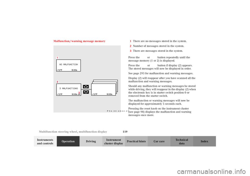
cluster displayPractical hints Car care Index Malfunction / warning message memory 1There are no messages stored in the system.
2Number of messages stored in the system.
3There are messages stored in the system.
Press the è or ÿ button repeatedly until the
message memory (1 or 2) is displayed.
Press the j or k button if display (2) appears.
The stored messages will now be displayed in order.
See page 293 for malfunction and warning messages.
Display (2) will reappear after you have scanned all the
malfunction and warning messages.
Should any malfunction or warning messages be stored
while driving, they will reappear in the display (2) when
the electronic key is in starter switch position 0 or
removed from the starter switch.
The malfunction or warning messages will now be
displayed for approximately 5 seconds each.
Pressing the reset knob on the instrument cluster
(see page 98) displays the malfunction and warning
messages once more.
P 54.30-4644-27
OM_203.book Seite 119 Donnerstag, 31. Mai 2001 11:57 11
Page 126 of 406

123 Multifunction steering wheel, multifunction display
Te ch n i c a l
data Instruments
and controlsOperationDrivingInstrument
cluster displayPractical hints Car care Index To return menu “SETTINGS” (2) to its factory
setting:
•Call up the individual setting preliminary
display (1) or display (2).
•Press the reset knob on the instrument cluster
(see page 98) for approximately 3 seconds.
Display (3) will appear.
•Press the reset knob on the instrument cluster once
more. The menu “SETTINGS” is reset to factory
settings, acknowledged by display (4).
The individual setting preliminary display (1) will
appear if you do not press the reset knob on the
instrument cluster within about 5 seconds. The
setting menus will not be reset.Note:
For safety reasons, the individual setting “LIGHT
CIRCUIT HEADLAMP MODE” in menu “LIGHTING”
cannot be reset while driving, see page 130. If an
attempt is made, the message “LIGHTING” – “CANNOT
BE COMPLETELY RESET TO FACTORY SETTINGS
WHILE DRIVING” will be displayed.
OM_203.book Seite 123 Donnerstag, 31. Mai 2001 11:57 11