2002 MERCEDES-BENZ C230 KOMPRESSOR COUPE Turn signals
[x] Cancel search: Turn signalsPage 151 of 399
148 Combination switch
Te ch n i c a l
data Instruments
and controlsOperationDrivingInstrument
cluster displayPractical hints Car care Index
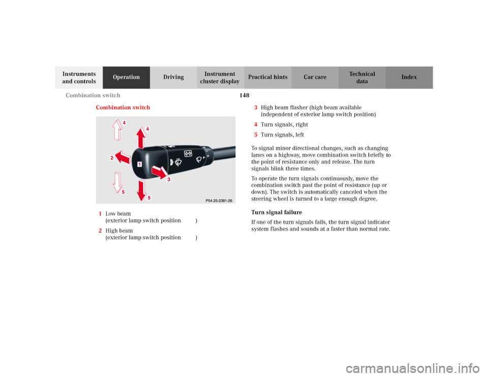
Combination switch
1Low beam
(exterior lamp switch position B)
2High beam
(exterior lamp switch position B)3High beam flasher (high beam available
independent of exterior lamp switch position)
4Turn signals, right
5Turn signals, left
To signal minor directional changes, such as changing
lanes on a highway, move combination switch briefly to
the point of resistance only and release. The turn
signals blink three times.
To operate the turn signals continuously, move the
combination switch past the point of resistance (up or
down). The switch is automatically canceled when the
steering wheel is turned to a large enough degree.
Turn signal failure
If one of the turn signals fails, the turn signal indicator
system flashes and sounds at a faster than normal rate.
Page 154 of 399
151 Hazard warning flasher
Te ch n i c a l
data Instruments
and controlsOperationDrivingInstrument
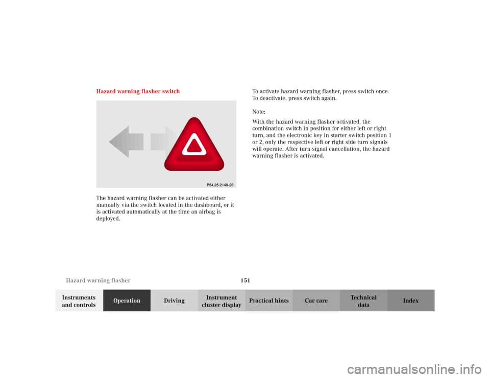
cluster displayPractical hints Car care Index Hazard warning flasher switch
The hazard warning flasher can be activated either
manually via the switch located in the dashboard, or it
is activated automatically at the time an airbag is
deployed.To activate hazard warning flasher, press switch once.
To deactivate, press switch again.
Note:
With the hazard warning flasher activated, the
combination switch in position for either left or right
turn, and the electronic key in starter switch position 1
or 2, only the respective left or right side turn signals
will operate. After turn signal cancellation, the hazard
warning flasher is activated.
Page 236 of 399
233 Tele Aid
Te ch n i c a l
data Instruments
and controlsOperationDrivingInstrument
cluster displayPractical hints Car care Index Notes:
The indicator lamp in the Roadside Assistance
button remains illuminated in red for approx.
10 seconds during the system self-check after turning
electronic key in starter switch to position 2 (together
with the “SOS” button and the Information
button¡).
See system self-check on page 228 when the indicator
lamp does not light up in red or stays on longer than
approximately 10 seconds.
If the indicator lamp in the Roadside Assistance
button is illuminated continuously and there was
no voice connection to the Response Center established,
then the Tele Aid system could not initiate an Roadside
Assistance call (e.g. the relevant cellular phone network
is not available). The message “ROADSIDE
ASSISTANCE – CALL FAILED” appears in the
multifunction display.
Roadside Assistance calls can be terminated using the
ìbutton on the multifunction steering wheel.Information button ¡
Located below the center armrest cover is the
Information button¡. Pressing and holding the
button (for longer than 2 seconds) will initiate a call to
the Customer Assistance Center. The button will flash
while the call is in progress. The message “INFO –
CONNECTING CALL” will appear in the multifunction
display. When the connection is established, the
message “INFO – CALL CONNECTED” appears in the
multifunction display. The Tele Aid system will transmit
data generating the vehicle identification number,
model, color and location (subject to availability of
cellular and GPS signals).
A voice connection between the Customer Assistance
Center representative and the occupants of the vehicle
will be established. When a voice connection is
established the audio system mutes and the message
“TELE AID – INFO CALL ACTIVE” appears in the
multifunction display. Information regarding the
operation of your vehicle, the nearest Mercedes-Benz
Center or Mercedes-Benz USA products and services is
ava i l ab le to yo u .
For more details concerning Tele Aid, please visit
www.mbusa.com and use your ID and password, sent to
you separately, to learn more (USA only).
Page 237 of 399

234 Tele Aid
Te ch n i c a l
data Instruments
and controlsOperationDrivingInstrument
cluster displayPractical hints Car care Index
Notes:
The indicator lamp in the Information button¡
remains illuminated in red for approx. 10 seconds
during the system self-check after turning electronic
key in starter switch to position 2 (together with the
“SOS” button and the Roadside Assistance button).
See system self-check on page 228 when the indicator
lamp does not light up in red or stays on longer than
approximately 10 seconds.
If the indicator lamp in the Information button¡ is
illuminated continuously and there was no voice
connection to the Response Center established, then the
Tele Aid system could not initiate an Information call
(e.g. the relevant cellular phone network is not
available). The message “INFO – CALL FAILED” appears
in the multifunction display.
Information calls can be terminated using the
ìbutton on the multifunction steering wheel.Important!
If the indicator lamps do not start flashing after
pressing one of the buttons or remain illuminated (in
red) at any time, the Tele Aid system has detected a fault
or the service is not currently active, and may not
initiate a call.
Visit your Mercedes-Benz Center and have the system
checked or contact the Response Center at 1-800-756-
9018 (in the USA) or 1-888-923-8367 (in Canada) as
soon as possible.
Upgrade Signals
Tele Aid system processes calls using the following
priority.
•Automatic emergency – First priority
•Manual emergency – Second priority
•Roadside assistance – Third priority
•Information – Fourth priority
Should a higher priority call be initiated while you are
connected, an upgrade (alternating) tone will be heard,
and the appropriate indicator lamp will flash. If certain
information such as vehicle identification number or
Customer information is not available, the operator may
Page 353 of 399
350 Exterior lamps
Te ch n i c a l
data Instruments
and controlsOperation DrivingInstrument
cluster displayPractical hintsCar care Index
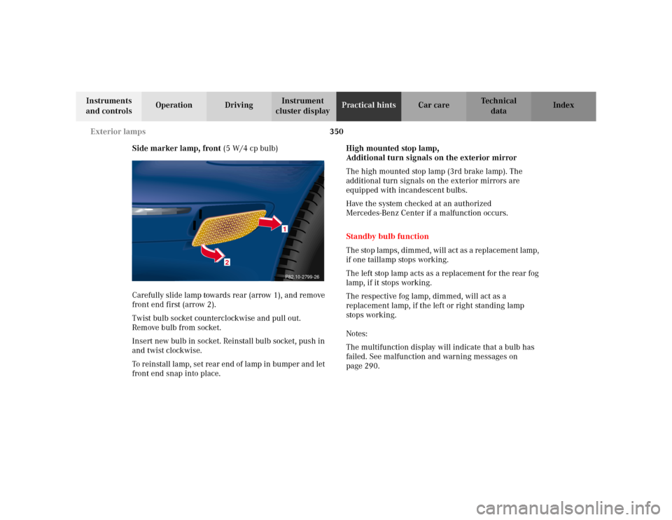
Side marker lamp, front (5 W/4 cp bulb)
Carefully slide lamp towards rear (arrow 1), and remove
front end first (arrow 2).
Twist bulb socket counterclockwise and pull out.
Remove bulb from socket.
Insert new bulb in socket. Reinstall bulb socket, push in
and twist clockwise.
To reinstall lamp, set rear end of lamp in bumper and let
front end snap into place.High mounted stop lamp,
Additional turn signals on the exterior mirror
The high mounted stop lamp (3rd brake lamp). The
additional turn signals on the exterior mirrors are
equipped with incandescent bulbs.
Have the system checked at an authorized
Mercedes-Benz Center if a malfunction occurs.
Standby bulb function
The stop lamps, dimmed, will act as a replacement lamp,
if one taillamp stops working.
The left stop lamp acts as a replacement for the rear fog
lamp, if it stops working.
The respective fog lamp, dimmed, will act as a
replacement lamp, if the left or right standing lamp
stops working.
Notes:
The multifunction display will indicate that a bulb has
failed. See malfunction and warning messages on
page 290.
2
1P82.10-2799-26
Page 390 of 399
387 Index
Te ch n i c a l
data Instruments
and controlsOperation DrivingInstrument
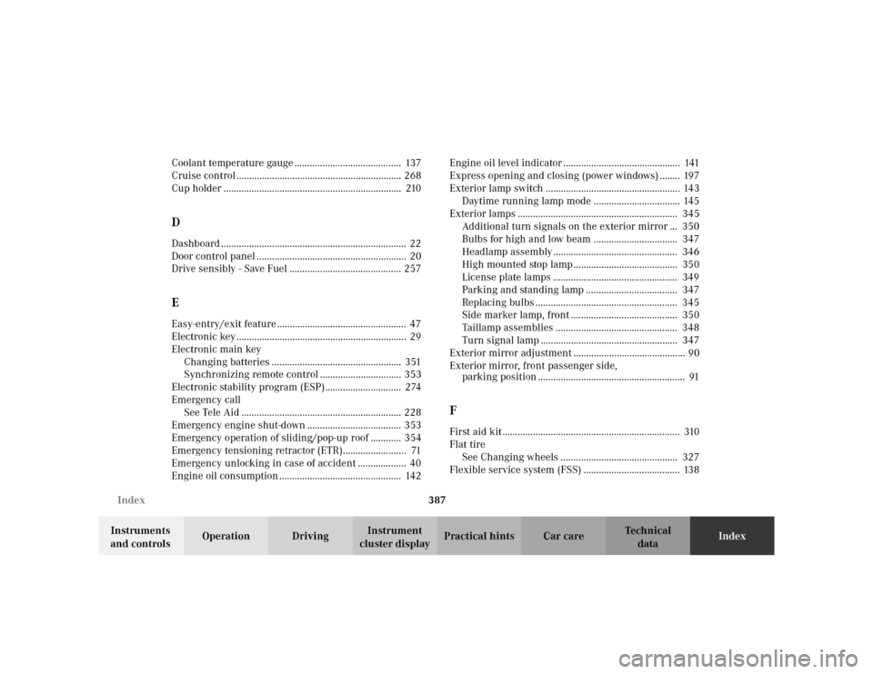
cluster displayPractical hints Car careIndex Coolant temperature gauge .......................................... 137
Cruise control ................................................................. 268
Cup holder ...................................................................... 210
DDashboard ......................................................................... 22
Door control panel ........................................................... 20
Drive sensibly - Save Fuel ............................................ 257EEasy-entry/exit feature ................................................... 47
Electronic key ................................................................... 29
Electronic main key
Changing batteries ................................................... 351
Synchronizing remote control ................................ 353
Electronic stability program (ESP).............................. 274
Emergency call
See Tele Aid ............................................................... 228
Emergency engine shut-down ..................................... 353
Emergency operation of sliding/pop-up roof ............ 354
Emergency tensioning retractor (ETR)......................... 71
Emergency unlocking in case of accident ................... 40
Engine oil consumption ................................................ 142Engine oil level indicator .............................................. 141
Express opening and closing (power windows) ........ 197
Exterior lamp switch ..................................................... 143
Daytime running lamp mode .................................. 145
Exterior lamps ............................................................... 345
Additional turn signals on the exterior mirror ... 350
Bulbs for high and low beam ................................. 347
Headlamp assembly ................................................. 346
High mounted stop lamp ......................................... 350
License plate lamps ................................................. 349
Parking and standing lamp .................................... 347
Replacing bulbs ........................................................ 345
Side marker lamp, front .......................................... 350
Taillamp assemblies ................................................ 348
Turn signal lamp ...................................................... 347
Exterior mirror adjustment ............................................ 90
Exterior mirror, front passenger side,
parking position .......................................................... 91
FFirst aid kit ...................................................................... 310
Flat tire
See Changing wheels .............................................. 327
Flexible service system (FSS) ...................................... 138