Page 291 of 399

288 Malfunction and indicator lamps
Te ch n i c a l
data Instruments
and controlsOperation DrivingInstrument
cluster displayPractical hints Car care Index
Electronic stability program (ESP) — warning lamp
The yellow ESP warning lamp in the
speedometer dial comes on with the
electronic key in starter switch position 2.
It should go out with engine running.
If the ESP malfunction indicator lamp remains
illuminated with the engine running, a malfunction has
been detected in the system. Pressing the accelerator
pedal will require greater effort. Only partial engine
output will be available.
See electronic stability program (ESP) on page 274 if the
warning lamp lights up or flashes when the vehicle is
moving.Seat belt nonusage warning lamp
With the electronic key in starter switch
position 2, the seat belt nonusage warning
lamp comes on, and a warning sounds for a
short time if the drivers seat belt is not fastened.
After starting the engine, the seat belt nonusage
warning lamp blinks for a brief period to remind the
driver and passengers to fasten seat belts.
Page 292 of 399

289 Malfunction and indicator lamps
Te ch n i c a l
data Instruments
and controlsOperation DrivingInstrument
cluster displayPractical hints Car care Index Malfunction and indicator lamp in the center
console
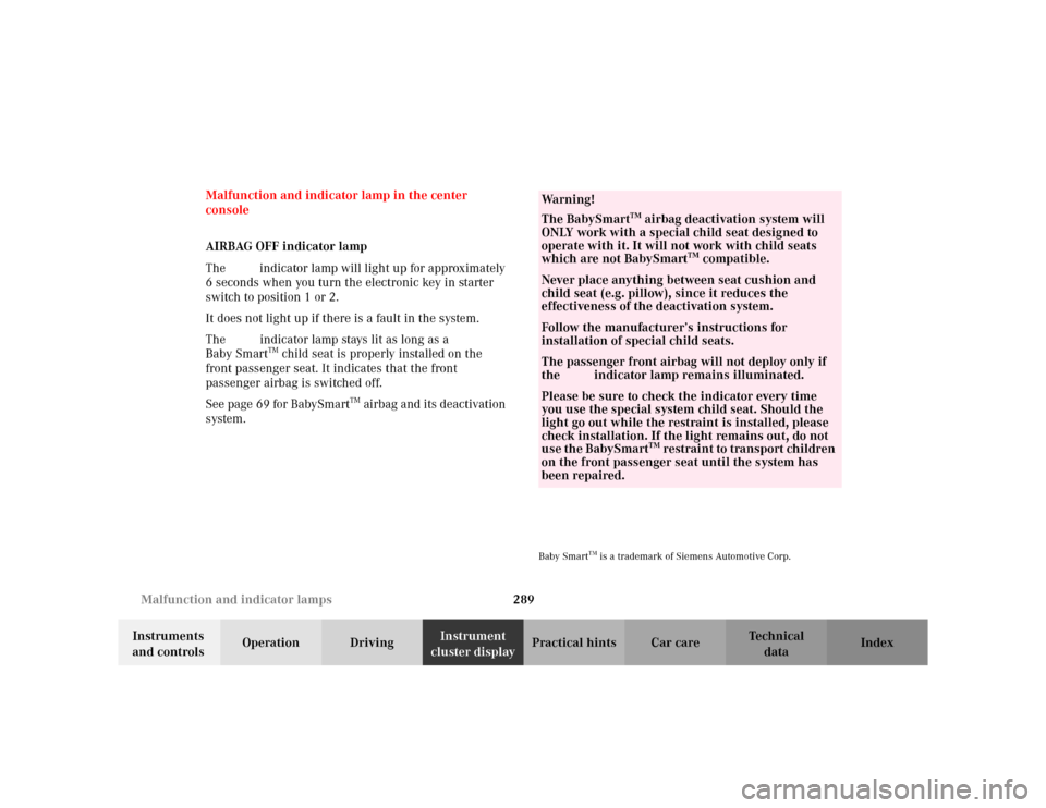
AIRBAG OFF indicator lamp
The ü indicator lamp will light up for approximately
6 seconds when you turn the electronic key in starter
switch to position 1 or 2.
It does not light up if there is a fault in the system.
The ü indicator lamp stays lit as long as a
Baby Smart
TM child seat is properly installed on the
front passenger seat. It indicates that the front
passenger airbag is switched off.
See page 69 for BabySmart
TM airbag and its deactivation
system.
Baby Smart
TM is a trademark of Siemens Automotive Corp.
Wa r n i n g !
The BabySmart
TM airbag deactivation system will
ONLY work with a special child seat designed to
operate with it. It will not work with child seats
which are not BabySmart
TM compatible.
Never place anything between seat cushion and
child seat (e.g. pillow), since it reduces the
effectiveness of the deactivation system.Follow the manufacturer’s instructions for
installation of special child seats.The passenger front airbag will not deploy only if
the ü indicator lamp remains illuminated.Please be sure to check the indicator every time
you use the special system child seat. Should the
light go out while the restraint is installed, please
check installation. If the light remains out, do not
use the BabySmart
TM restraint to transport children
on the front passenger seat until the system has
been repaired.
Page 303 of 399
300 Malfunction and warning messages
Te ch n i c a l
data Instruments
and controlsOperation DrivingInstrument
cluster displayPractical hints Car care Index
LIGHTING SYSTEM
Line 1 Line 2 C*
LOW BEAM,L CHECK LAMP! 2
LOW BEAM,R CHECK LAMP! 2
DISPLAY DEFECTIVE VISIT WORKSHOP!
1
2
TURN SIGNAL, L CHECK LAMP! 2
TURN SIGNAL, R CHECK LAMP! 2
L. TURN SIG. RFLECTR CHECK LAMP! 2
R. TURN SIG. RFLECTR CHECK LAMP! 2
TURN SIGNAL F, L CHECK LAMP! 2
TURN SIGNAL F, R CHECK LAMP! 2
BRAKE LIGHT
2
VISIT WORKSHOP! 2
BRAKE LIGHT, L
3
CHECK LAMP! 2
BRAKE LIGHT, R
3
CHECK LAMP! 2
3RD STOP LAMP
3
CHECK LAMP! 2
HIGH BEAM, L CHECK LAMP! 2
HIGH BEAM, R CHECK LAMP! 2
LICENSE PLATE L, L CHECK LAMP! 2
LICENSE PLATE L, R CHECK LAMP! 2
LIGHTS SWITCH OFF LIGHTS! 1
AUTOM. LIGHT ON REMOVE KEY! 1
FRONT FOGLAMP, L CHECK LAMP! 2
FRONT FOGLAMP, R CHECK LAMP! 2
REAR FOGLAMP CHECK LAMP! 2 Line 1 Line 2 C*
Page 309 of 399
306 Malfunction and warning messages
Te ch n i c a l
data Instruments
and controlsOperation DrivingInstrument
cluster displayPractical hints Car care Index
RESTRAINT SYSTEM
* C = Category, see page 290.See page 62 for notes on the seat belts, and page 72 for
notes on the airbags.KEY
* C = Category, see page 290.
1 Key needs possibly to be replaced. Line 1 Line 2 C*
RESTRAINT SYSTEM VISIT WORKSHOP! 1Line 1 Line 2 C*
REPLACE KEY
1
VISIT WORKSHOP! 2
AUTOM. LIGHT ON REMOVE KEY! 1
Page 312 of 399

309 Contents - Practical hints
Te ch n i c a l
data Instruments
and controlsOperation DrivingInstrument
cluster displayPractical hintsCar care Index
Practical hintsFirst aid kit...................................... 310
Stowing things in the vehicle ...... 311
Fuses ................................................ 311
Hood ................................................. 315
Automatic transmission
fluid level ................................... 317
Adding engine oil........................... 318
Coolant level ................................... 319
Adding coolant............................ 319
Windshield and headlamp
washer system ........................... 320
Spare wheel, storage
compartment.............................. 321Vehicle tools and air pump .......... 322
Vehicle jack .................................... 323
Wheels ............................................ 324
Tire replacement........................ 324
Rotating wheels ......................... 325
Spare wheel .................................... 326
Changing wheels ........................... 327
Inflating the collapsible
spare tire ..................................... 333
Storing spare wheel in
wheel well ................................... 334
Tire inflation pressure ................. 335
Battery............................................. 336
Jump starting.................................. 338Towing the vehicle......................... 341
Transmission selector lever,
manually unlocking ................... 344
Exterior lamps ................................ 345
Replacing bulbs .......................... 345
Changing batteries in the
electronic main key .................. 351
Synchronizing remote
control .......................................... 353
Emergency engine shut-down ..... 353
Fuel filler flap, manual release ... 354
Replacing wiper blade insert ....... 356
Roof rack ......................................... 357
Page 336 of 399

333 Tires, Wheels
Te ch n i c a l
data Instruments
and controlsOperation DrivingInstrument
cluster displayPractical hintsCar care Index Inflating the collapsible spare tire
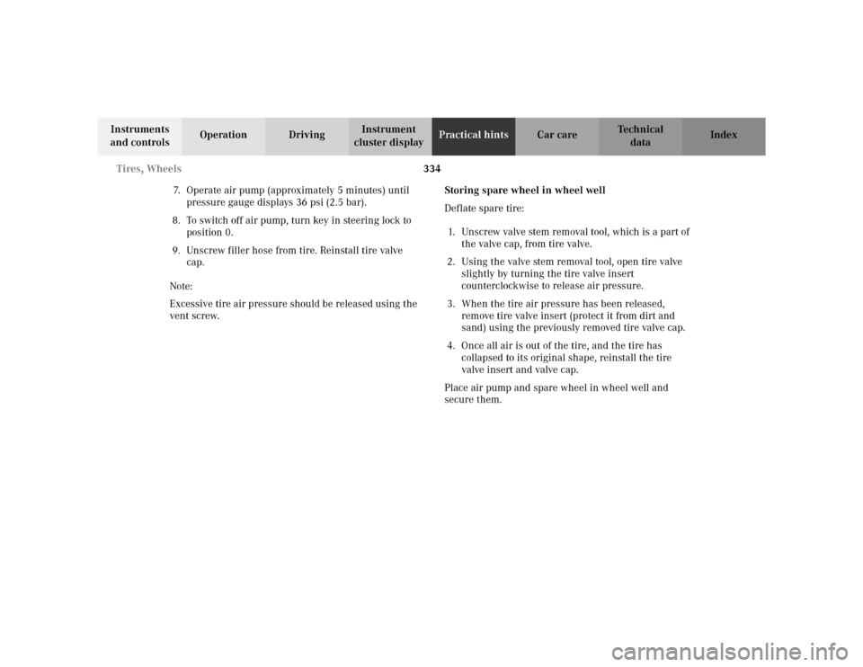
The air pump is located inside the wheel well in the
trunk, see page 322.
1Filler hose
2Electrical plug
3Pressure gauge with vent screw1. Remove air pump from storage compartment inside
trunk.
2. Open lid and pull out air hose with pressure gauge
and electrical plug.
Observe instructions on air pump label.
3. Unscrew tire valve cap from spare wheel tire valve.
4. Screw filler hose onto tire valve.
5. Plug air pump electrical plug into vehicle cigar
lighter.
6. To switch on air pump, turn key in steering lock to
position 1.
Important!
Do not start engine.
P40.10-2124-26
1
0
45 6max. 6 min
A 170 584 01 38 AIR COMPRESSOR 23
Mercedes-Benz
2
3
2 1
1
2,5 bar
36 psi1
0 23
4
5
620PSI
BAR40
60
80
LUFTPRESSER12
12
3
Wa r n i n g !
To prevent possible injury when unscrewing air
pump filler hose from tire valve after inflating the
tire, use a rag since the tire valve could be hot.
Page 337 of 399

334 Tires, Wheels
Te ch n i c a l
data Instruments
and controlsOperation DrivingInstrument
cluster displayPractical hintsCar care Index
7. Operate air pump (approximately 5 minutes) until
pressure gauge displays 36 psi (2.5 bar).
8. To switch off air pump, turn key in steering lock to
position 0.
9. Unscrew filler hose from tire. Reinstall tire valve
cap.
Note:
Excessive tire air pressure should be released using the
vent screw.Storing spare wheel in wheel well
Deflate spare tire:
1. Unscrew valve stem removal tool, which is a part of
the valve cap, from tire valve.
2. Using the valve stem removal tool, open tire valve
slightly by turning the tire valve insert
counterclockwise to release air pressure.
3. When the tire air pressure has been released,
remove tire valve insert (protect it from dirt and
sand) using the previously removed tire valve cap.
4. Once all air is out of the tire, and the tire has
collapsed to its original shape, reinstall the tire
valve insert and valve cap.
Place air pump and spare wheel in wheel well and
secure them.
Page 339 of 399

336 Battery
Te ch n i c a l
data Instruments
and controlsOperation DrivingInstrument
cluster displayPractical hintsCar care Index
Battery
Important!
Battery replacement information:
The maintenance-free battery is located in the engine
compartment on the right hand side.
The service life of the battery is dependent on its
condition of charge. The battery should always be kept
sufficiently charged, in order to last an optimum length
of time.Therefore, we strongly recommend that you have the
battery charge checked frequently, and corrected if
necessary, especially if you use the vehicle less than
approximately 200 miles (300 km) per month,
mostly for short distance trips, or if it is not used for
long periods of time.
Only charge a battery with a battery charger after the
battery has been disconnected from the vehicle’s
electrical circuit.
Always disconnect the battery negative lead first and
connect last.
When removing and connecting the battery, always
make sure that all electrical consumers are off and the
electronic key is in starter switch position 0. The
battery, its filler caps, the vent tube and the opposite
plug must always be securely installed when the vehicle
is in operation.
While the engine is running the battery terminal clamps
must not be loosened or detached, otherwise the
generator and other electronic components would be
damaged.
Wa r n i n g !
Failure to follow these instructions can result in
severe injury or death.Never lean over batteries while connecting, you
might get injured.Battery fluid contains sulfuric acid. Do not allow
this fluid to come in contact with eyes, skin or
clothing. In case it does, immediately flush affected
area with water and seek medical help if necessary.A battery will also produce hydrogen gas, which is
flammable and explosive. Keep flames or sparks
away from battery, avoid improper connection of
jumper cables, smoking etc.