2002 MERCEDES-BENZ C CLASS COUPE airbag
[x] Cancel search: airbagPage 154 of 399

151
Hazard warning flasher
Te ch n i c a l
data
Instruments
and controls Operation
DrivingInstrument
cluster display Practical hints Car care Index
Hazard warning flasher switch
The hazard warning flasher can be activated either
manually via the switch located in the dashboard, or it
is activated automatically at the time an airbag is
deployed.
To activate hazard warning flasher, press switch once.
To deactivate, press switch again.
Note:
With the hazard warning flasher activated, the
combination switch in position for either left or right
turn, and the electronic key in starter switch position 1
or 2, only the respective left or right side turn signals
will operate. After turn signal cancellation, the hazard
warning flasher is activated.
Page 232 of 399

229
Tele Aid
Te ch n i c a l
data
Instruments
and controls Operation
DrivingInstrument
cluster display Practical hints Car care Index
Important!
Always make sure that the indicator lamps in the
“SOS” button, in the “Roadside Assistance” button and
in the “Information” button do not remain illuminated
constantly in red and the message “TELE AID – VISIT
WORKSHOP” is not displayed in the multifunction
display after the system self check.
If a malfunction is indicated as outlined above, have the
system checked at the nearest Mercedes-Benz Center as
soon as possible.
Emergency calls
An emergency call is initiated automatically:
• following an accident in which the Emergency
Tensioning Retractors (ETR’s) or airbags deploy,
• if the antitheft alarm or the tow-away alarm stays on
for more than 20 seconds, see pages 44 and 46.
An emergency call can also be initiated manually by
opening the cover next to the inside rear view mirror
labeled “SOS”, then briefly pressing the button located
under the cover. See below for instructions on initiating
an emergency call manually. Once the emergency call is in progress, the indicator
lamp in the “SOS” button will begin to flash. The
message “EMERGENCY CALL – CONNECTING CALL”
appears in the multifunction display. When the
connection is established, the message “EMERGENCY
CALL – CALL CONNECTED” appears in the
multifunction display. All information relevant to the
emergency, such as the location of the vehicle
(determined by the GPS satellite location system),
vehicle model, identification number and color are
generated.
A voice connection between the Response Center and
the occupants of the vehicle will be established
automatically soon after the emergency call has been
initiated. When a voice connection is established the
audio system mutes and the message “TELE AID –
EMERGENCY CALL ACTIVE” appears in the
multifunction display. The Response Center will attempt
to determine more precisely the nature of the accident
provided they can speak to an occupant of the vehicle.
Page 284 of 399

281
Contents - Instrument cluster display
Te ch n i c a l
data
Instruments
and controls Operation Driving
Instrument
cluster display Practical hints Car care Index
Instrument cluster displayMalfunction and indicator
lamps in the instrument
cluster ......................................... 282
On-board diagnostic system ......... 283 Check engine malfunction
indicator lamp............................. 283
Brake warning lamp .................. 284
Supplemental restraint
system (SRS) indicator lamp .... 285
Fuel reserve warning................. 286
ABS malfunction indicator
lamp.............................................. 287
Electronic stability program
(ESP) — warning lamp ............... 288
Seat belt nonusage warning lamp ............................................288 Malfunction and indicator
lamp in the center console...... 289
AIRBAG OFF indicator lamp .... 289
Malfunction and warning messages in the
multifunction display .............. 290
DISPLAY DEFECTIVE................ 291
BATTERY / ALTERNATOR ....... 292
ANTILOCK BRAKE SYSTEM .... 293
BRAKE ASSIST........................... 293
BRAKE PAD WEAR.................... 294
BRAKE FLUID ............................ 294
PARKING BRAKE ....................... 295
SEAT BELT SYSTEM .................. 295
ELEC. STABIL. PROG.
(Electronic stability program).. 296
COOLANT (coolant level).......... 297 COOLANT
(coolant temperature) ................ 298
ENGINE OIL LEVEL ................... 299
LIGHTING SYSTEM .................... 300
LIGHT SENSOR........................... 302
DOOR............................................ 302
TRUNK OPEN ............................. 303
HOOD ........................................... 303
TELEPHONE – FUNCTION ....... 304
TELE AID ..................................... 304
WASHER FLUID.......................... 305
RESTRAINT SYSTEM ................. 306
KEY............................................... 306
FUEL RESERVE .......................... 307
UNDERVOLTAGE ........................ 307
STEERING WHEEL ADJUST. ..... 308
Page 288 of 399

285
Malfunction and indicator lamps
Te ch n i c a l
data
Instruments
and controls Operation Driving
Instrument
cluster display Practical hints Car care Index
Supplemental restraint system (SRS) indicator lamp
When turning the electronic key in starter
switch to position 1 the indicator lamp “SRS”
in the instrument cluster comes on. If no
fault is detected, the lamp will go out after
approximately 4 seconds.
When turning the electronic key in starter switch to
position 2 the indicator lamp “SRS” in the instrument
cluster comes on. If no fault is detected, the lamp will go
out when the engine is running.
The operational readiness of the airbag system is
verified by the indicator lamp “SRS” in the instrument
cluster when turning the electronic key in starter switch
to position 1 or 2.
After the lamp goes out, the system continues to
monitor the components and circuitry of the airbag
system and will indicate a malfunction by coming on
again. See page 72 for notes on airbags, see page 70 for belt
tensioners and page 62 for infant and child seat
restraint.
Wa r n i n g !
In the event a malfunction of the “SRS” is indicated
as outlined above, the “SRS” may not be
operational. For your safety, we strongly
recommend that you visit an authorized
Mercedes-Benz Center immediately to have the
system checked; otherwise the “SRS” may not be
activated when needed in an accident, which could
result in serious or fatal injury, or it might deploy
unexpectedly and unnecessarily which could also
result in injury.
Page 292 of 399

289
Malfunction and indicator lamps
Te ch n i c a l
data
Instruments
and controls Operation Driving
Instrument
cluster display Practical hints Car care Index
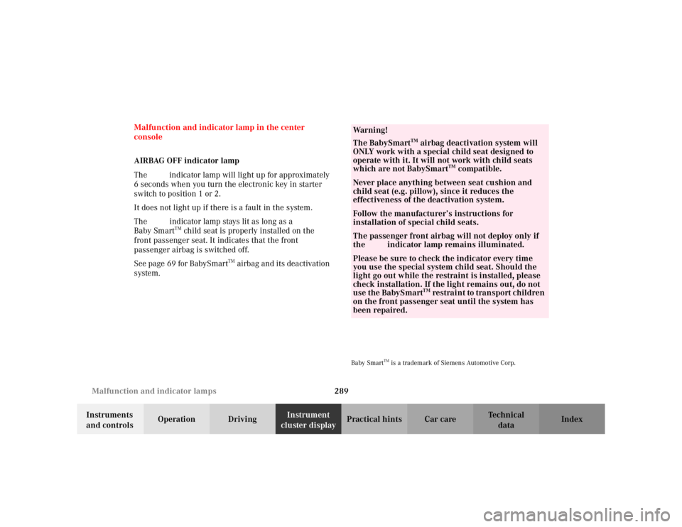
Malfunction and indicator lamp in the center
console
AIRBAG OFF indicator lamp
The
ü indicator lamp will light up for approximately
6 seconds when you turn the electronic key in starter
switch to position 1 or 2.
It does not light up if there is a fault in the system.
The ü indicator lamp stays lit as long as a
Baby Smart
TM child seat is properly installed on the
front passenger seat. It indicates that the front
passenger airbag is switched off.
See page 69 for BabySmart
TM airbag and its deactivation
system.
Baby Smart
TM is a trademark of Siemens Automotive Corp.
Wa r n i n g !
The BabySmart
TM airbag deactivation system will
ONLY work with a special child seat designed to
operate with it. It will not work with child seats
which are not BabySmart
TM compatible.
Never place anything between seat cushion and
child seat (e.g. pillow), since it reduces the
effectiveness of the deactivation system.Follow the manufacturer’s instructions for
installation of special child seats.The passenger front airbag will not deploy only if
the ü indicator lamp remains illuminated.Please be sure to check the indicator every time
you use the special system child seat. Should the
light go out while the restraint is installed, please
check installation. If the light remains out, do not
use the BabySmart
TM restraint to transport children
on the front passenger seat until the system has
been repaired.
Page 309 of 399

306
Malfunction and warning messages
Te ch n i c a l
data
Instruments
and controls Operation Driving
Instrument
cluster display Practical hints Car care Index
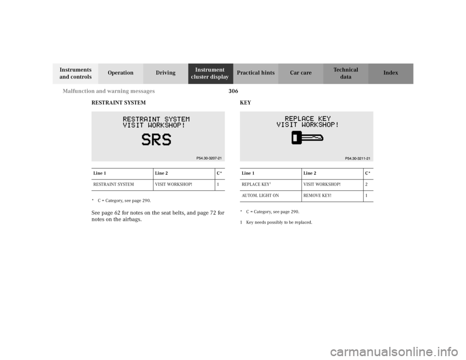
RESTRAINT SYSTEM
* C = Category, see page 290.See page 62 for notes on the seat belts, and page 72 for
notes on the airbags. KEY
* C = Category, see page 290.
1 Key needs possibly to be replaced.
Line 1 Line 2 C*
RESTRAINT SYSTEM VISIT WORKSHOP! 1Line 1
Line 2C*
REPLACE KEY
1
VISIT WORKSHOP! 2
AUTOM. LIGHT ON REMOVE KEY! 1
Page 388 of 399

385
Index
Te ch n i c a l
data
Instruments
and controls Operation Driving
Instrument
cluster display Practical hints Car care
Index
Index
AAdding engine oil........................................................... 318
Air pump ......................................................................... 322
Airbags .............................................................................. 72
ANTILOCK BRAKE SYSTEM
Malfunction and warning message........................ 293
Antilock brake system (ABS) ....................................... 272
Antitheft alarm system ................................................... 44
Ashtrays........................................................................... 211
Audio system Button and soft key operation................................. 176
Cassette mode ........................................................... 182
CD changer ................................................................ 187
CD mode ..................................................................... 186
Operating and display elements............................. 174
Operating safety ........................................................ 173
Operation.................................................................... 176
Operation Audio and telephone .............................. 173
Radio mode ................................................................ 179
Telephone operation ................................................. 190 Audio systems................................................................. 108
Cassette player .......................................................... 110
CD Player .................................................................... 109
Radio ........................................................................... 108
Automatic central locking .............................................. 40
Automatic climate control ............................................ 160 Activated charcoal filter ........................................... 168
Adjustable air outlets, rear passenger compartment ......................................................... 172
Air recirculation ........................................................ 167
Air volume, manual .................................................. 165
Basic setting............................................................... 164
Defrosting ................................................................... 166
Display and controls ................................................. 162
Dust filter.................................................................... 164
Economy mode .......................................................... 169
Front center console storage compartment ventilation..................................... 171
Residual engine heat utilization ............................. 169
Special settings ......................................................... 165
Windows fogged up on the outside ........................ 166
Automatic transmission ............................................... 246 Fluid level ................................................................... 317
Transmission selector lever, manually unlocking ............................................ 344
Page 389 of 399

386
Index
Te ch n i c a l
data
Instruments
and controls Operation Driving
Instrument
cluster display Practical hints Car care
Index
BBabySmart
TM airbag deactivation system..................... 69
Battery ............................................................................. 336
Block heater .................................................................... 266
Brake assist system (BAS) ............................................ 271
Bulbs See Replacing bulbs ................................................. 345
CCD changer installed ..................................................... 187
Cellular telephone ......................................................... 219
Center console .................................................................. 24
Central locking switch .................................................... 38
Central locking system ................................................... 31Automatic central locking ......................................... 40
Central locking switch ............................................... 38
Choosing global or selective mode........................... 33
Doors ............................................................................. 36
General notes............................................................... 30
Locking and unlocking with remote control .......... 33
Mechanical keys .......................................................... 35
Obtaining replacement keys ..................................... 29
Summer opening/convenience feature ................... 34 Vehicle keys ................................................................. 28
Changing wheels........................................................... 327 Inflating the collapsible spare tire ........................ 333
Storing spare wheel in wheel well ........................ 334
Check regularly and before a long trip...................... 280
Child seat See Infant and child restraint systems .................... 82
Climate control ............................................................... 152 Adjustable air outlets, rear passenger compartment ......................................................... 172
Air recirculation ........................................................ 158
Basic setting............................................................... 156
Defrosting ................................................................... 157
Display and controls ................................................. 154
Dust filter.................................................................... 155
Economy mode .......................................................... 159
Front center console storage compartment ventilation ............................................................. 171
Residual engine heat utilization ............................. 159
Special settings ......................................................... 156
Windows fogged up on the inside .......................... 157
Windows fogged up on the outside ................ 157, 166
COMAND, radio and telephone................................... 226
Combination switch ....................................................... 148
Control and operation of radio transmitters ............. 226
Coolant level ................................................................... 319