Page 336 of 399

333
Tires, Wheels
Te ch n i c a l
data
Instruments
and controls Operation Driving
Instrument
cluster display Practical hints
Car care Index
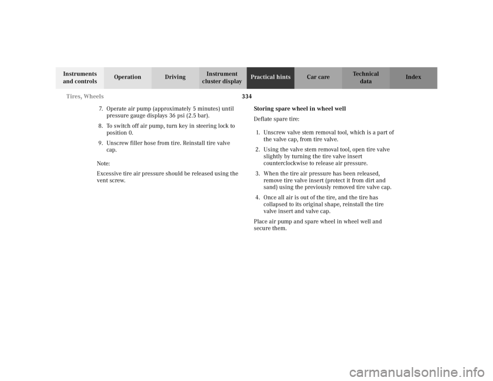
Inflating the collapsible spare tire
The air pump is located inside the wheel well in the
trunk, see page 322.
1 Filler hose
2 Electrical plug
3 Pressure gauge with vent screw 1. Remove air pump from storage compartment inside
trunk.
2. Open lid and pull out air hose with pressure gauge and electrical plug.
Observe instructions on air pump label.
3. Unscrew tire valve cap from spare wheel tire valve.
4. Screw filler hose onto tire valve.
5. Plug air pump electrical plug into vehicle cigar lighter.
6. To switch on air pump, turn key in steering lock to position 1.
Important!
Do not start engine.
P40.10-2124-26
1
0
45 6 max. 6 min
A 170 584 01 38 AIR COMPRESSOR
23
Mercedes-Benz
2
3
2 1
1
2,5 bar
36 psi1 0
2
3
4
5
620PSI
BAR40 60
80
LUFTPRESSER12
12
3
Wa r n i n g !
To prevent possible injury when unscrewing air
pump filler hose from tire valve after inflating the
tire, use a rag since the tire valve could be hot.
Page 337 of 399

334
Tires, Wheels
Te ch n i c a l
data
Instruments
and controls Operation Driving
Instrument
cluster display Practical hints
Car care Index
7. Operate air pump (approximately 5 minutes) until pressure gauge displays 36 psi (2.5 bar).
8. To switch off air pump, turn key in steering lock to position 0.
9. Unscrew filler hose from tire. Reinstall tire valve cap.
Note:
Excessive tire air pressure should be released using the
vent screw. Storing spare wheel in wheel well
Deflate spare tire:
1. Unscrew valve stem removal tool, which is a part of the valve cap, from tire valve.
2. Using the valve stem removal tool, open tire valve slightly by turning the tire valve insert
counterclockwise to release air pressure.
3. When the tire air pressure has been released, remove tire valve insert (protect it from dirt and
sand) using the previously removed tire valve cap.
4. Once all air is out of the tire, and the tire has collapsed to its original shape, reinstall the tire
valve insert and valve cap.
Place air pump and spare wheel in wheel well and
secure them.
Page 340 of 399

337
Battery
Te ch n i c a l
data
Instruments
and controls Operation Driving
Instrument
cluster display Practical hints
Car care Index
Removal of filter box:
Release three clamps (1) and remove filter box.
Installation of filter box:
Install filter box properly and secure with
three clamps (1). Notes:
The gear selector lever will remain locked in
position “P” and the electronic key can not be turned in
the starter switch, if the vehicle battery is disconnected
or discharged.
After reconnecting the battery also set the clock
(vehicles with COMAND: see COMAND operator’s
manual) resynchronize the front seat head restraints,
the express feature of the power windows, the
panorama sliding / pop-up roof, and the electronic
stability program (see individual settings on page 121,
head restraints on page 54, power windows on page 197,
synchronizing the sliding / pop-up roof on page 202 and
electronic stability program on page 274).
Battery recycling
Batteries contain materials that can harm the
environment with improper disposal.
Large 12 Volt storage batteries contain lead.
Recycling of batteries is the preferred method of
disposal.
Many states require sellers of batteries to accept old
batteries for recycling.
Page 344 of 399

341
Towing the vehicle
Te ch n i c a l
data
Instruments
and controls Operation Driving
Instrument
cluster display Practical hints
Car care Index
Towing the vehicle
Important!
When towing the vehicle, please, note the following:
With the automatic central locking activated and the
electronic key in starter switch position 2, the vehicle
doors lock if the left front wheel as well as the right rear
wheel are turning at vehicle speeds of approximately
9 mph (15 km / h) or more.
To prevent the vehicle door locks from locking,
deactivate the automatic central locking. See the
individual setting menu “VEHICLE” – “AUTOMATIC
DOOR LOCK” on page 132.
Towing of the vehicle should only be done using the
properly installed towing eye bolt. Never attach tow
cable, tow rope or tow rod to vehicle chassis, frame
or suspension parts.
Notes:
The selector lever will remain locked in position “P” and
the electronic key cannot be turned in the starter switch
if the battery is disconnected or discharged. See battery
on page 336 or jump starting on page 338.
Transmission selector lever, manually unlocking, see
page 344.
Wa r n i n g !
Prior to towing the vehicle with all wheels on the
ground, make certain that the electronic key is in
starter switch position 2.If the electronic key is left in the starter switch
position 0 for an extended period of time, it can no
longer be turned in the switch. In this case, the
steering is locked. To unlock, remove electronic key
from starter switch and reinsert.
Page 347 of 399
344
Towing the vehicle
Te ch n i c a l
data
Instruments
and controls Operation Driving
Instrument
cluster display Practical hints
Car care Index
Transmission selector lever, manually unlocking
In the case of power failure the transmission selector
lever can be manually unlocked, e.g. to tow the vehicle. To do so, open storage compartment in front of center
armrest.
Using a small coin, release the coin holder (1) and
swing it aside.
Insert a tool (2), e.g. the screw driver, into the opening
below the coin holder. While pushing the tool down,
move selector lever from position “P”.
After removal of the tool from the opening, reinstall the
coin holder.
The selector lever is locked again when moving it to
position “P”.
Page 350 of 399

347
Exterior lamps
Te ch n i c a l
data
Instruments
and controls Operation Driving
Instrument
cluster display Practical hints
Car care Index
Bulbs for high and low beam
H7 (55 W)
Open hood.
Press the clamp and remove headlamp cover (1 or 2).
Pull electrical connector off.
Unclip the retainer spring and take out the bulb.
Insert the new bulb so that the base locates in the
recess on the holder.
Clip in retainer springs and plug the connector onto the
bulb.
Align headlamp cover (1 or 2) and click into place.
Turn signal lamp
1156 NA (26.9 / 5 W/32/4 cp)
Open hood.
Twist bulb socket (3) counterclockwise and pull out.
Push bulb into socket, turn counterclockwise and
remove.
Insert new bulb in socket, push in and twist clockwise.
Reinstall bulb socket.
Parking and standing lamp
W 5W
Open hood.
Press the clamp and remove headlamp cover (2).
Pull out bulb socket (6). Remove bulb from socket.
Insert new bulb in socket and push in. Reinstall bulb
socket.
Align headlamp cover (2) and click into place.
Page 351 of 399
348
Exterior lamps
Te ch n i c a l
data
Instruments
and controls Operation Driving
Instrument
cluster display Practical hints
Car care Index
Taillamp assemblies
Open trunk lid.
Turn both handles (2) and remove trim panel (1). Press together the latches (3) and remove bulb carrier.
Push bulb into socket, turn counterclockwise and
remove.
Insert new bulb in socket, push in and reinstall bulb
carrier.
Reinstall trim panel.
Page 353 of 399

350
Exterior lamps
Te ch n i c a l
data
Instruments
and controls Operation Driving
Instrument
cluster display Practical hints
Car care Index
Side marker lamp, front (5 W/4 cp bulb)
Carefully slide lamp towards rear (arrow 1), and remove
front end first (arrow 2).
Twist bulb socket counterclockwise and pull out.
Remove bulb from socket.
Insert new bulb in socket. Reinstall bulb socket, push in
and twist clockwise.
To reinstall lamp, set rear end of lamp in bumper and let
front end snap into place. High mounted stop lamp,
Additional turn signals on the exterior mirror
The high mounted stop lamp (3rd brake lamp). The
additional turn signals on the exterior mirrors are
equipped with incandescent bulbs.
Have the system checked at an authorized
Mercedes-Benz Center if a malfunction occurs.
Standby bulb function
The stop lamps, dimmed, will act as a replacement lamp,
if one taillamp stops working.
The left stop lamp acts as
a replacement for the rear fog
lamp, if it stops working.
The respective fog lamp, dimmed, will act as a
replacement lamp, if the left or right standing lamp
stops working.
Notes:
The multifunction display will indicate that a bulb has
failed. See malfunction and warning messages on
page 290.
2
1P82.10-2799-26