2002 MAZDA 6 ABS
[x] Cancel search: ABSPage 8 of 909

NEW STANDARDS
GI–5
GINEW STANDARDS TABLEA6E202800020201•The following is a comparison of the previous standard and the new standard.
NEW STANDARDS
New Standard Previous Standard
Remark
Abbrevi-
ationNameAbbrevi-
ationName
AP Accelerator Pedal—Accelerator Pedal
ACL Air Cleaner—Air Cleaner
A/C Air Conditioning—Air Conditioning
BARO Barometric Pressure—Atmospheric Pressure
B+ Battery Positive VoltageV
BBattery Voltage
—Brake Switch—Stoplight Switch
—Calibration Resistor—Corrected Resistance #6
CMP sensor Camshaft Position Sensor—Crank Angle Sensor
CAC Charge Air Cooler—Intercooler
CLS Closed Loop System—Feedback System
CTP Closed Throttle Position—Fully Closed
—Closed Throttle Position Switch—Idle Switch
CPP Clutch Pedal Position—Clutch Position
CIS Continuous Fuel Injection System EGI Electronic Gasoline Injection System
CS sensor Control Sleeve Sensor CSP sensor Control Sleeve Position Sensor #6
CKP sensor Crankshaft Position Sensor—Crank Angle Sensor 2
DLC Data Link Connector—Diagnosis Connector
DTM Diagnostic Test Mode—Test Mode #1
DTC Diagnostic Trouble Code—Service Code(s)
DI Distributor Ignition—Spark Ignition
DLI Distributorless Ignition—Direct Ignition
EI Electronic Ignition—Electronic Spark Ignition #2
ECT Engine Coolant Temperature—Water Thermo
EM Engine Modification—Engine Modification
—Engine Speed Input Signal—Engine RPM Signal
EVAP Evaporative Emission—Evaporative Emission
EGR Exhaust Gas Recirculation—Exhaust Gas Recirculation
FC Fan Control—Fan Control
FF Flexible Fuel—Flexible Fuel
4GR Fourth Gear—Overdrive
—Fuel Pump Relay—Circuit Opening Relay #3
FSO
solenoidFuel Shut Off Solenoid FCV Fuel Cut Valve #6
GEN Generator—Alternator
GND Ground—Ground/Earth
HO2S Heated Oxygen Sensor—Oxygen Sensor With heater
IAC Idle Air Control—Idle Speed Control
—IDM Relay—Spill Valve Relay #6
—Incorrect Gear Ratio——
—Injection Pump FIP Fuel Injection Pump #6
—Input/Turbine Speed Sensor—Pulse Generator
IAT Intake Air Temperature—Intake Air Thermo
KS Knock Sensor—Knock Sensor
MIL Malfunction Indicator Lamp—Malfunction Indicator Light
MAP Manifold Absolute Pressure—Intake Air Pressure
MAF sensor Mass Air Flow Sensor—Airflow Sensor
MFI Multiport Fuel Injection—Multiport Fuel Injection
OBD On Board Diagnostic—Diagnosis/Self Diagnosis
Page 10 of 909

ABBREVIATIONS
GI–7
GIABBREVIATIONS TABLEA6E203000011202
End Of Sie
ABBREVIATIONS
A/C Air conditioner
ABS Antilock brake system
ACC Accessories
ABDC After bottom dead center
ATDC After top dead center
ATF Automatic transaxle fluid
ATX Automatic transaxle
BBDC Before bottom dead center
BDC Bottom dead center
BTDC Before top dead center
CAN Controller area network
CM Control module
DEI Double electronic ignition
DOHC Double overhead camshaft
DSC Dynamic stability control
ESA Electronic spark advance
EX Exhaust
HI High
HU Hydraulic unit
IDM Injector driver module
IG Ignition
IN Intake
KOEO Key on engine off
KOER Key off engine running
LH Left hand
L.H.D. Left hand drive
LO Low
LR Left rear
M Motor
MAX Maximum
MTX Manual transaxle
MIN Minimum
O/D Overdrive
OCV Oil control valveOFF Switch off
ON Switch on
P/S Power steering
PATS Passive anti-theft system
PCV Positive crankcase ventilation
PID Parameter identification
RF Right front
RH Right hand
R.H.D. Right hand drive
RR Right rear
SST Special service tool
SW Switch
TCC Torque converter clutch
TCM Transaxle control module
TDC Top dead center
TFT Transaxle fluid temperature
TNS Tail number side lights
TR Transaxle range
TWC Three way catalytic converter
VAD Variable air duct
VBC Variable boost control
VIS Variable intake-air system
VSC Variable swirl control
VSS Vehicle speedometer sensor
VTCS Variable tumble control system
WGN Wagon
WDS Worldwide diagnostic system
1GR 1st gear
2GR 2nd gear
4GR 4th gear
5GR 5th gear
4SD 4 door sedan
5HB 5 door hatchback
4WD 4 wheel drive
Page 100 of 909

F1–12
FUEL SYSTEM
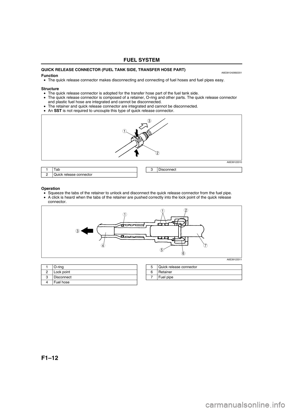
QUICK RELEASE CONNECTOR (FUEL TANK SIDE, TRANSFER HOSE PART)A6E391242692201Function
•The quick release connector makes disconnecting and connecting of fuel hoses and fuel pipes easy.
Structure
•The quick release connector is adopted for the transfer hose part of the fuel tank side.
•The quick release connector is composed of a retainer, O-ring and other parts. The quick release connector
and plastic fuel hose are integrated and cannot be disconnected.
•The retainer and quick release connector are integrated and cannot be disconnected.
•An SST is not required to uncouple this type of quick release connector.
.
Operation
•Squeeze the tabs of the retainer to unlock and disconnect the quick release connector from the fuel pipe.
•A click is heard when the tabs of the retainer are pushed correctly into the lock point of the quick release
connector.
.
End Of Sie
3
1
2
A6E39122010
1Tab
2 Quick release connector3 Disconnect
7
5
4
3
6
1
21
A6E39122011
1 O-ring
2 Lock point
3 Disconnect
4Fuel hose5 Quick release connector
6 Retainer
7 Fuel pipe
Page 107 of 909

CONTROL SYSTEM
F1–19
F1
CONTROL DEVICE AND CONTROL RELATIONSHIP CHARTA6E394018880204Input devices
x: Applicable
*
1: For unleaded fuel (RON 90 or above) model
*2: For MTX model
*3: For 2WD ATX model
Component
IAT sensor x x x xxxx×
MAF sensor x xx xxxxx
TP sensor x x x x x x x x
MAP sensor x x
ECT sensor xx xxx xxxxx x
CMP sensor x x
CKP sensor xxxxxxxxxxxxx
Knock sensor x
Front HO2S x x
Rear HO2S x
BARO sensor*
1x
Neutral switch*
2xxxx
Clutch switch*
2xxxxx
TR switch*
3xxxxx
Brake switch
PSP switch x x x
VSS×
A/C switch, refrigerant
pressure switch (high,
low pressure)xxx××
Refrigerant pressure
switch (middle pressure)×
Battery voltage x x x×
Generator terminal P
(Generation voltage)xxx×
ABS/TCS HU/CM×
Coil×
Idle air control (IAC)Variable air duct (VAD)
controlVariable intake-air
control (VIC)Variable tumble
control system (VTCS)Variable valve timing controlFuel injection controlFuel pump controlElectronic spark advance
(ESA) controlPurge controlEGR controlFront HO2S heater controlRear HO2S heater controlA/C cut-off controlElectrical fan controlGenerator controlTraction controlImmobilizer system
Page 108 of 909

F1–20
CONTROL SYSTEM
Output devices
×: Applicable
* : For L3 engine
End Of Sie
Component
IAC valve×
VAD control solenoid valve*×
VIC solenoid valve*×
Variable tumble control
solenoid valve×
Oil control valve (OCV)*×
Fuel injectors××
Fuel pump relay×
Ignition coil××
Purge solenoid valve×
EGR valve×
HO2S heaters××
A/C relay×
Cooling fan relay×
Generator (terminal D: field
coil)×
ABS/TCS HU/CM×
Idle air control (IAC)Variable air duct (VAD)
controlVariable intake-air
control (VIC)Variable tumble
control system (VTCS)Variable valve timing controlFuel injection controlFuel pump controlElectronic spark advance
(ESA) controlPurge controlEGR controlFront HO2S heater controlRear HO2S heater controlA/C cut-off controlElectrical fan controlGenerator controlTraction controlImmobilizer system
Page 109 of 909

CONTROL SYSTEM
F1–21
F1
CONTROLLER AREA NETWORK (CAN)A6E394018880205•PCM transmit/received the information in the CAN. For detail information of the CAN, see the “MULTIPLEX
COMMUNICATION SYSTEM.” (See T–3 OUTLINE.)
Transmit Information (4WD ATX Model)
•Engine control condition
•Torque reduction inhibit
•Engine speed
•Vehicle Speed
•TP
•Engine torque (without torque reduction)
•Engine torque (with torque reduction)
•Battery reconnection
•Engine loss torque
•ECT
•Travelled distance
•Fuel injection information
•MIL condition
•Generator warning light conditions
•Engine displacement
•Number of cylinders
•Air induction type
•Fuel type and delivery
•Country
•Transmission/axle type
•Tire circumference (front/rear)
Received Information (4WD ATX Model)
From ABS HU/CM, ABS/TCS HU/CM, or DSC HU/CM
•Wheel speed
—Front left, Front right, Rear left, and Rear right
•Travelled distance
•Brake system status
•Torque reduction request
•Brake system configuration
From TCM
•Desired torque
•Upper torque limit
•Turbineshaft speed
•Vehicle speed
•Torque reduction request
•Idle speed up request
•Racing select determination
•MIL indicate request
•Desired gear/selector lever position
•AT warning indicator light condition
•TCC condition
End Of Sie
Page 115 of 909

FUEL SYSTEM
F1–27
F1
Plastic Fuel Hose Removal Note
Caution
•The quick release connector may be damaged if the tab is bent excessively. Do not expand the tab
over the stopper.
1. Disconnect the quick release connector.
(1) Push the tab on the locking coupler 90
degrees until it stops.
(2) Pull the fuel hose straight back.
Note
•The stopper may be removed from the quick
connector. Take care not to lose it.
Reinstall it to the quick release connector
before reconnecting the fuel line.
•The locking coupler has two internal locking
tabs which retain the fuel pipe. Be sure that
the tab on the locking coupler is rotated until
it stops to release two internal locking tabs.
2. Cover the disconnected quick release connector
and fuel pipe with vinyl sheets or the like to
prevent them from being scratched or
contaminated with foreign material.
Fuel Pump Cap Removal Note
1. Using the SST, remove the fuel pump cap.
FUEL PIPE
STOPPER TAB
A6E3912W001
LOCKING TAB
A6E3912W002
A6E39122015
49 T042 001A
A6E39122012
Page 116 of 909

F1–28
FUEL SYSTEM
Fuel Pump Cap Installation Note
1. Verify that the fuel tank mark is aligned with the
fuel pump unit mark as shown.
2. Using the SST, tighten the fuel pump cap without
shifting the mark.
Tightening torque
80—90 N·m {8.2—9.1 kgf·m, 60—66 ft·lbf}
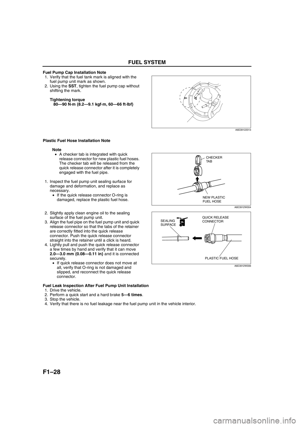
Plastic Fuel Hose Installation Note
Note
•A checker tab is integrated with quick
release connector for new plastic fuel hoses.
The checker tab will be released from the
quick release connector after it is completely
engaged with the fuel pipe.
1. Inspect the fuel pump unit sealing surface for
damage and deformation, and replace as
necessary.
•If the quick release connector O-ring is
damaged, replace the plastic fuel hose.
2. Slightly apply clean engine oil to the sealing
surface of the fuel pump unit.
3. Align the fuel pipe on the fuel pump unit and quick
release connector so that the tabs of the retainer
are correctly fitted into the quick release
connector. Push the quick release connector
straight into the retainer until a click is heard.
4. Lightly pull and push the quick release connector
a few times by hand and verify that it can move
2.0—3.0 mm {0.08—0.11 in} and it is connected
securely.
•If quick release connector does not move at
all, verify that O-ring is not damaged and
slipped, and reconnect the quick release
connector.
Fuel Leak Inspection After Fuel Pump Unit Installation
1. Drive the vehicle.
2. Perform a quick start and a hard brake 5—6 times.
3. Stop the vehicle.
4. Verify that there is no fuel leakage near the fuel pump unit in the vehicle interior.
End Of Sie
A6E39122013
CHECKER
TA B
NEW PLASTIC
FUEL HOSE
A6E3912W004
OILOIL
PLASTIC FUEL HOSE QUICK RELEASE
CONNECTOR SEALING
SURFACE
A6E3912W006