Page 85 of 248
²To program position two, repeat the previous procedure using control 2.
²To program position three, repeat the previous procedure but press
controls 1 and 2 simultaneously.
A position can only be recalled when the transmission gearshift is in
Park. A memory seat position may be programmed at any time.
The memory positions are also recalled when you press your remote
entry transmitter UNLOCK control.
To program the memory settings to remote entry transmitter, refer to
Remote entry systemin theCLocks and Security chapter.
REAR CENTER CONSOLE FEATURES (IF EQUIPPED)
The rear center console incorporates the following features:
²utility compartment
²cupholders
²auxiliary power point (if equipped)
²remote radio/climate controls (if equipped)
²remote seat adjustment (if equipped)
Radio/climate controls
Refer toSteering Wheel Controlsin
this chapter for operation
instructions.
NEXT
MODE
Driver Controls
85
Page 161 of 248
Fuse/Relay
LocationFuse Amp
RatingPassenger Compartment Fuse
Panel Description
9 20A Lighting Control Module (LCM),
Multi-Function Switch, Hi Beam
Headlamps
10 10A Restraint Control Module (RCM),
Air Bags
11 Ð Not Used
12 15A Instrument Cluster, Anti-Theft,
Ignition Switch, Ignition Coils
13 10A Anti-Lock Brake Module, Traction
Control Switch
14 7.5A Transmission Control Switch,
Lighting Control Module (LCM),
VCS
15 20A Multi-Function Switch, Turn
Signals
16 30A Wiper Control Module (WCM),
Windshield Wiper Motor
17 10A Digital Transmission Range (DTR)
Sensor, Back-Up Lamps, EC
Mirrors
18 7.5A Lighting Control Module (LCM),
Front Radio Control Unit, Cellular
Telephone Transceiver, Electronic
Day/Night Mirror, Compass
Module/Rear Audio/Climate
Control Module, VCS
19 10A EATC, Clock, Instrument Cluster,
PCM
20 7.5A Lighting Control Module (LCM),
ABS, Shift Lock
21 20A Multi-Function Switch, Hazard
Lamps
Roadside Emergencies
161
Page 168 of 248
5. Locate pry off notch (if
equipped) and remove the center
ornament from the aluminum wheel
with the tapered end of the wheel
nut wrench that came with your
vehicle. Insert and twist the handle,
then pry against the wheel.
6. Loosen each wheel lug nut
one-half turn counterclockwise but
do not remove them until the wheel is raised off the ground.
Before placing the jack under the vehicle, NOTE the jack location
markings:
JACK LOCATION
The jack location markings can be
foundon the lower outer edge of
the body.
²Locate the jack locator mark (B)
on the body (C) near the tire you
are changing, then place the jack
(D)under the frame (A) of
the vehiclealigning it with the
mark (B).
²Position the jack according to the
following guides and turn the jack
handle clockwise until the wheel
is completely off the ground.
B
C
D
A
Roadside Emergencies
168
Page 169 of 248

To lessen risk of personnal
injury, do not put any part
of your body under the vehicle
while changing a tire. Do not start
the engine when your vehicle is
on the jack. The jack is ONLY
meant for changing the tire.
²Never use the rear differential
as a jacking point.
7. Remove the lug nuts with the lug wrench.
8. Replace the flat tire with the spare tire, making sure the valve stem is
facing outward. Reinstall lug nuts until the wheel is snug against the hub.
Do not fully tighten the lug nuts until the wheel has been lowered.
9. Lower the vehicle by turning the jack handle counterclockwise.
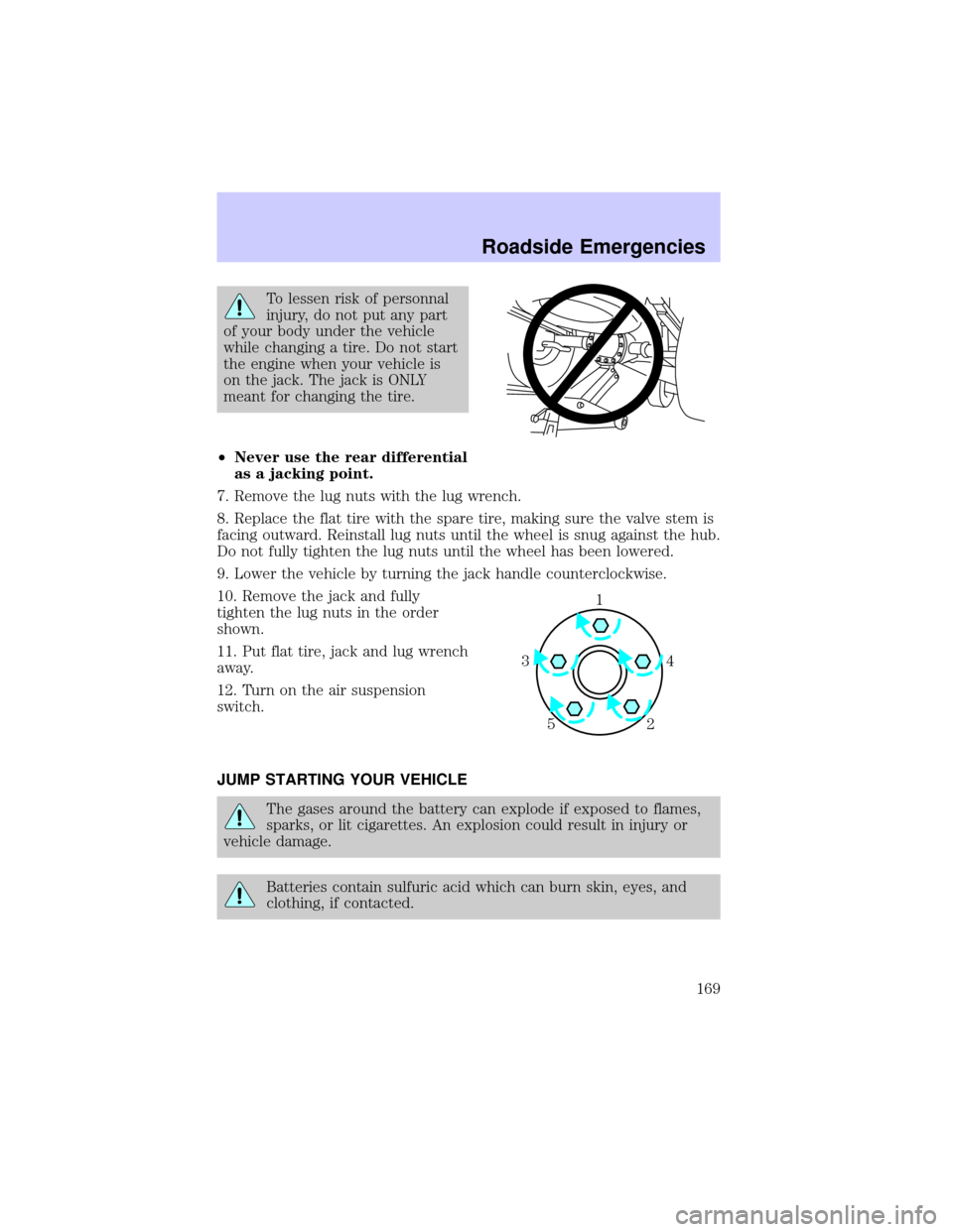
10. Remove the jack and fully
tighten the lug nuts in the order
shown.
11. Put flat tire, jack and lug wrench
away.
12. Turn on the air suspension
switch.
JUMP STARTING YOUR VEHICLE
The gases around the battery can explode if exposed to flames,
sparks, or lit cigarettes. An explosion could result in injury or
vehicle damage.
Batteries contain sulfuric acid which can burn skin, eyes, and
clothing, if contacted.
1
4 3
2 5
Roadside Emergencies
169
Page 197 of 248

²If required, add engine oil to the
engine. Refer toAdding engine
oilin this chapter.
²Do not overfill the engine
with oil. Oil levels above this
mark may cause engine
damage.If the engine is
overfilled, some oil must be removed from the engine by a qualified
service technician.
7. Put the indicator back in and ensure it is fully seated.
Adding engine oil
1. Check the engine oil. For instructions, refer toChecking the engine
oilin this chapter.
2. If the engine oil level is not within the normal operating range, add
only certified engine oil of the recommended viscosity. Remove the
engine oil filler cap and use a funnel to pour the engine oil into the
opening.
3. Recheck the engine oil level. Make sure the oil level is not above the
normal operating range on the engine oil level indicator (dipstick).
4. Install the indicator and ensure it is fully seated.
5. Fully install the engine oil filler cap by turning the filler cap clockwise
until three clicks can be heard.
To avoid possible oil loss, DO NOT operate the vehicle with the
engine oil level indicator and/or the engine oil filler cap removed.
DO NOT OVERFILL
Maintenance and Specifications
197
Page 201 of 248

If the battery has been disconnected or a new battery has been installed,
the clock must be reset once the battery is reconnected.
²Always dispose of automotive
batteries in a responsible manner.
Follow your local authorized
standards for disposal. Call your
local authorized recycling center
to find out more about recycling
automotive batteries.
ENGINE COOLANT
Checking engine coolant
The concentration and level of engine coolant should be checked at the
mileage intervals listed in the scheduled maintenance guide. The coolant
concentration should be maintained at 50/50 coolant and water, which
equates to a freeze point of -36É C (-34É F). Coolant concentration
testing is possible with a hydrometer or antifreeze tester (such as the
Rotunda Battery and Antifreeze Tester, 014±R1060). The level of coolant
should be maintained at the ªcold fullº of ªcold fill rangeº level in the
coolant reservoir. If the level falls below, add coolant per the instructions
in theAdding Engine Coolantsection.
Your vehicle was factory-filled with a 50/50 engine coolant and water
concentration. If the concentration of coolant falls below 40% or above
60%, the engine parts could become damaged or not work properly.A
50±50 mixture of coolant and water provides the following:
²Freeze protection down to -36É C (-34É F).
²Boiling protection up to 129É C (265É F).
²Protection against rust and other forms of corrosion.
²Enables calibrated gauges to work properly.
LEAD
RETURN
RECYCLE
Maintenance and Specifications
201
Page 204 of 248

To avoid personal injury, make sure the engine is cool before
unscrewing the coolant pressure relief cap. The cooling system is
under pressure; steam and hot liquid can come out forcefully when the
cap is loosened slightly.
1. Before you begin, turn the engine off and let it cool.
2. When the engine is cool, wrap a thick cloth around the coolant
pressure relief cap on the coolant reservoir (an opaque plastic bottle).
Slowly turn cap counterclockwise (left) until pressure begins to release.
3. Step back while the pressure releases.
4. When you are sure that all the pressure has been released, use the
cloth to turn it counterclockwise and remove the cap.
5. Fill the coolant reservoir slowly with the proper coolant mixture (see
above), to within the ªcold fill rangeº or the ªcold fullº level on the
reservoir. If you removed the radiator cap in an overflow system, fill the
radiator until the coolant is visible and radiator is almost full.
6. Replace the cap. Turn until tightly installed. (Cap must be tightly
installed to prevent coolant loss.)
After any coolant has been added, check the coolant concentration see
Checking Engine Coolant section). If the concentration is not 50/50
(protection to ±34É F/±36É C), drain some coolant and adjust the
concentration. It may take several drains and additions to obtain a 50/50
coolant concentration.
Whenever coolant has been added, the coolant level in the coolant
reservoir should be checked the next few times you drive the vehicle. If
necessary, add enough 50/50 concentration of engine coolant and
distilled water to bring the liquid level to the proper level.
If you have to add more than 1.0 liter (1.0 quart) of engine coolant per
month, have your dealer check the engine cooling system. Your cooling
system may have a leak. Operating an engine with a low level of coolant
can result in engine overheating and possible engine damage.
Maintenance and Specifications
204
Page 210 of 248

When fueling your vehicle:
1. Turn the engine off.
2. Carefully turn the filler cap counterclockwise 1/8 of a turn until it
stops.
3. Pull to remove the cap from the fuel filler pipe.
4. To install the cap, align the tabs on the cap with the notches on the
filler pipe.
5. Turn the filler cap clockwise 1/8 of a turn until it stops.
The ªCheck Fuel Capº light illuminates when the ignition is turned to the
ON position. It will also illuminate when the fuel filler cap is not properly
installed. Proper fuel filler cap installation is checked automatically as
the vehicle is driven, but not until after some fuel is used (fuel guage
drops below full). Once the fuel filler cap is properly secured, the ªCheck
Fuel Capº light will turn off after a short period of driving.
If you must replace the fuel filler cap, replace it with a fuel filler
cap that is designed for your vehicle. The customer warranty may
be void for any damage to the fuel tank or fuel system if the
correct genuine Ford or Motorcraft fuel filler cap is not used.
The fuel system may be under pressure. If the fuel filler cap is
venting vapor or if you hear a hissing sound, wait until it stops
before completely removing the fuel filler cap. Otherwise, fuel may
spray out and injure you or others.
If you do not use the proper fuel filler cap, excessive pressure or
vacuum in the fuel tank may damage the fuel system or cause
the fuel cap to disengage in a collision, which may result in possible
personal injury.
Choosing the right fuel
Use only UNLEADED FUEL. The use of leaded fuel is prohibited by law
and could damage your vehicle.
Do not use fuel containing methanol. It can damage critical fuel system
components.
Your vehicle was not designed to use fuel or fuel additives with metallic
compounds, including manganese-based compounds containing MMT.
Maintenance and Specifications
210