Page 129 of 248

BRAKES
Your service brakes are self-adjusting. Refer to the scheduled
maintenance guide for scheduled maintenance.
Occasional brake noise is normal and often does not indicate a
performance concern with the vehicle's brake system. In normal operation,
automotive brake systems may emit occasional or intermittent squeal or
groan noises when the brakes are applied. Such noises are usually heard
during the first few brake applications in the morning; however, they may
be heard at any time while braking and can be aggravated by
environmental conditions such as cold, heat, moisture, road dust, salt or
mud. If a ªmetal-to-metal,º ªcontinuous grindingº or ªcontinuous squealº
sound is present while braking, the brake linings may be worn-out and
should be inspected by a qualified service technician.
Four-wheel anti-lock brake system (ABS)
This vehicle is equipped with an anti-lock braking system (ABS). A noise
from the hydraulic pump motor and pulsation in the pedal may be
observed during ABS braking events. Pedal pulsation coupled with noise
while braking under panic conditions or on loose gravel, bumps, wet or
snowy roads is normal and indicates proper functioning of the vehicle's
anti-lock brake system. If the vehicle has continuous vibration or shudder
in the steering wheel while braking, the vehicle should be inspected by a
qualified service technician.
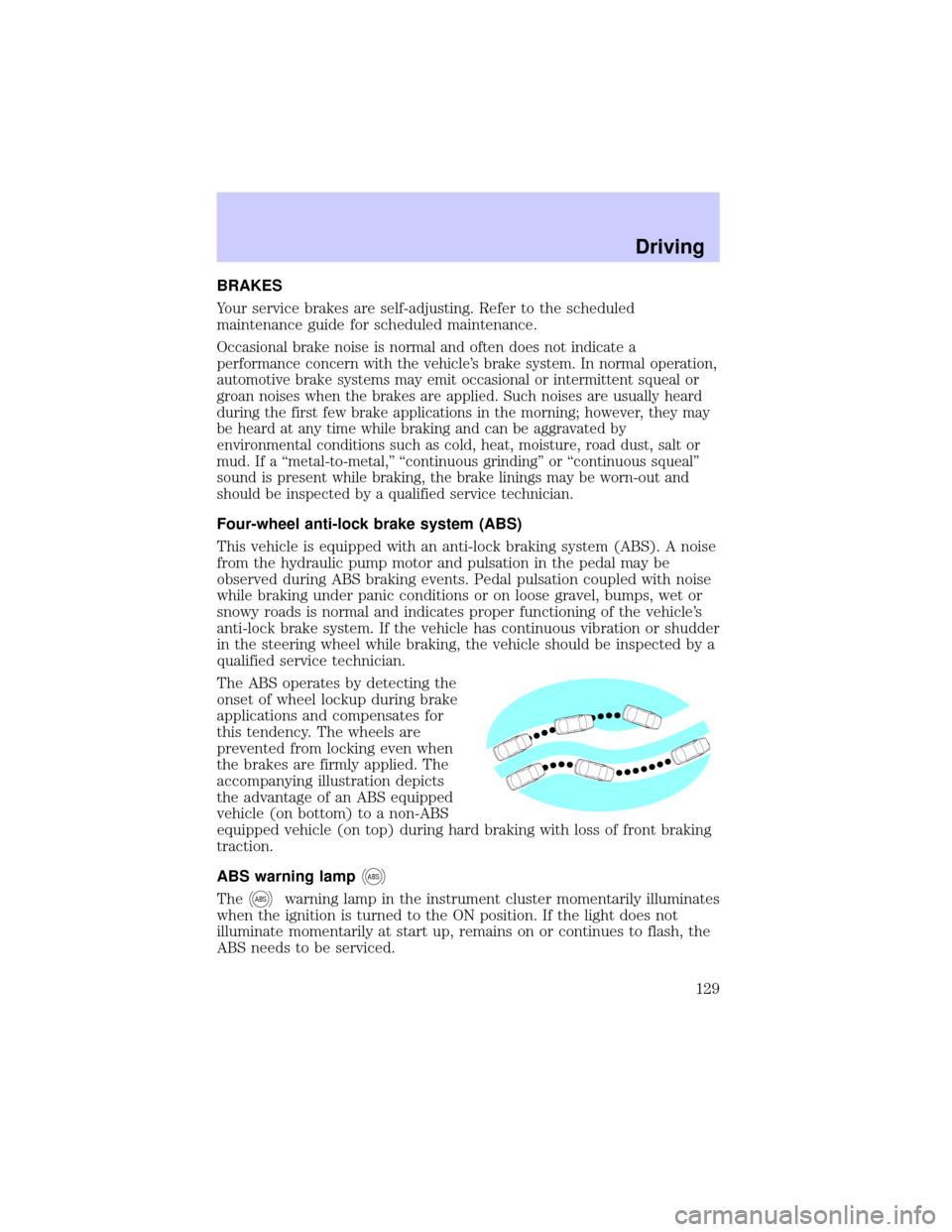
The ABS operates by detecting the
onset of wheel lockup during brake
applications and compensates for
this tendency. The wheels are
prevented from locking even when
the brakes are firmly applied. The
accompanying illustration depicts
the advantage of an ABS equipped
vehicle (on bottom) to a non-ABS
equipped vehicle (on top) during hard braking with loss of front braking
traction.
ABS warning lamp
ABS
TheABSwarning lamp in the instrument cluster momentarily illuminates
when the ignition is turned to the ON position. If the light does not
illuminate momentarily at start up, remains on or continues to flash, the
ABS needs to be serviced.
Driving
129
Page 130 of 248

With the ABS light on, the anti-lock
brake system is disabled and normal
braking is still effective unless the
brake warning light also remains
illuminated with parking brake
released. (If your brake warning lamp illuminates, have your vehicle
serviced immediately.)
Using four wheel ABS
²In an emergency or when maximum efficiency from the four wheel
ABS is required, apply continuous force on the brake. The four wheel
ABS will be activated immediately, thus allowing you to retain full
steering control of your vehicle and, providing there is sufficient
space, will enable you to avoid obstacles and bring the vehicle to a
controlled stop.
²The anti-lock system does not decrease the time necessary to apply
the brakes or always reduce stopping distance. Always leave enough
room between your vehicle and the vehicle in front of you to stop.
²We recommend that you familiarize yourself with this braking
technique. However, avoid taking any unnecessary risks.
Parking brake with auto-release
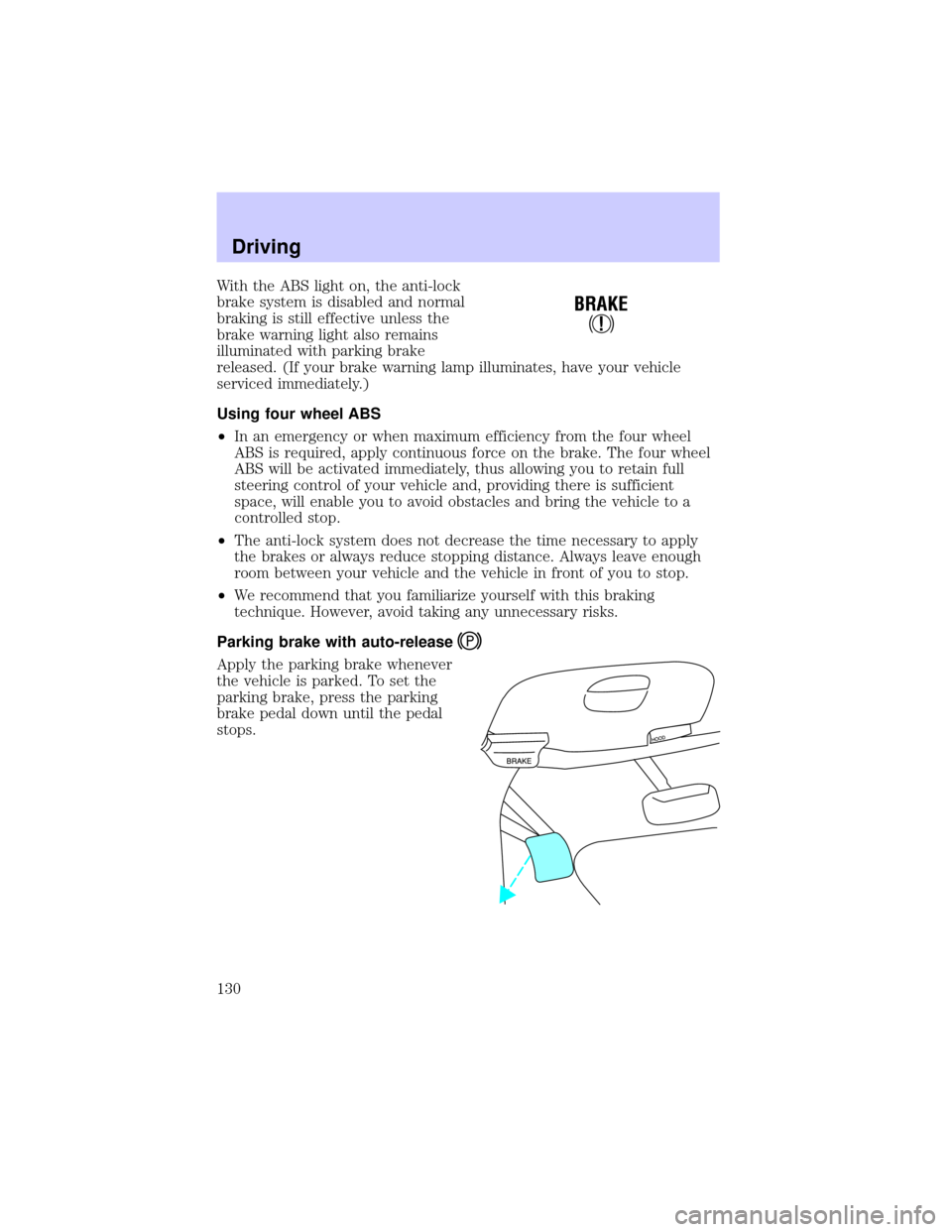
Apply the parking brake whenever
the vehicle is parked. To set the
parking brake, press the parking
brake pedal down until the pedal
stops.
!
BRAKE
Driving
130
Page 132 of 248

STEERING
Your vehicle is equipped with power steering. Power steering uses energy
from the engine to help steer the vehicle.
To prevent damage to the power steering pump:
²Never hold the steering wheel to the extreme right or the extreme left
for more than a few seconds when the engine is running.
²Do not operate the vehicle with a low power steering pump fluid level
(below the MIN mark on the reservoir).
If the power steering system breaks down (or if the engine is turned
off), you can steer the vehicle manually, but it takes more effort.
If the steering wanders or pulls, the condition could be caused by any of
the following:
²underinflated tire(s) on any wheel(s)
²uneven vehicle loading
²high crown in center of road
²high crosswinds
²wheels out of alignment
²loose or worn suspension components
AIR SUSPENSION SYSTEM
The air suspension system is designed to improve ride, handling and
general vehicle performance for static, on and off-road driving conditions.
²The load leveling feature of the air suspension automatically keeps the
vehicle at a constant level if a load is added or removed from the
vehicle.
Driving
132
Page 148 of 248

If you need to arrange roadside assistance for yourself, Ford will
reimburse a reasonable amount. To obtain reimbursement information,
U.S. Ford or Mercury vehicles customers call 1-800-241-3673; Lincoln
vehicle customers call 1±800±521±4140.
Canadian customers who need to obtain reimbursement information, call
1±800±665±2006.
Roadside coverage beyond basic warranty
In the United States, you may purchase additional roadside assistance
coverage beyond this period through the Ford Auto Club by contacting
your Ford or Lincoln Mercury dealer.
Similarly in Canada, for uninterrupted Roadside Assistance coverage, you
may purchase extended coverage prior to your Basic Warranty's Roadside
Assistance expiring. For more information and enrollment, contact
1±877±294±2582 or visit our website at www.ford.ca.
HAZARD FLASHER
Use only in an emergency to warn traffic of vehicle breakdown,
approaching danger, etc. The hazard flashers can be operated when the
ignition is off.
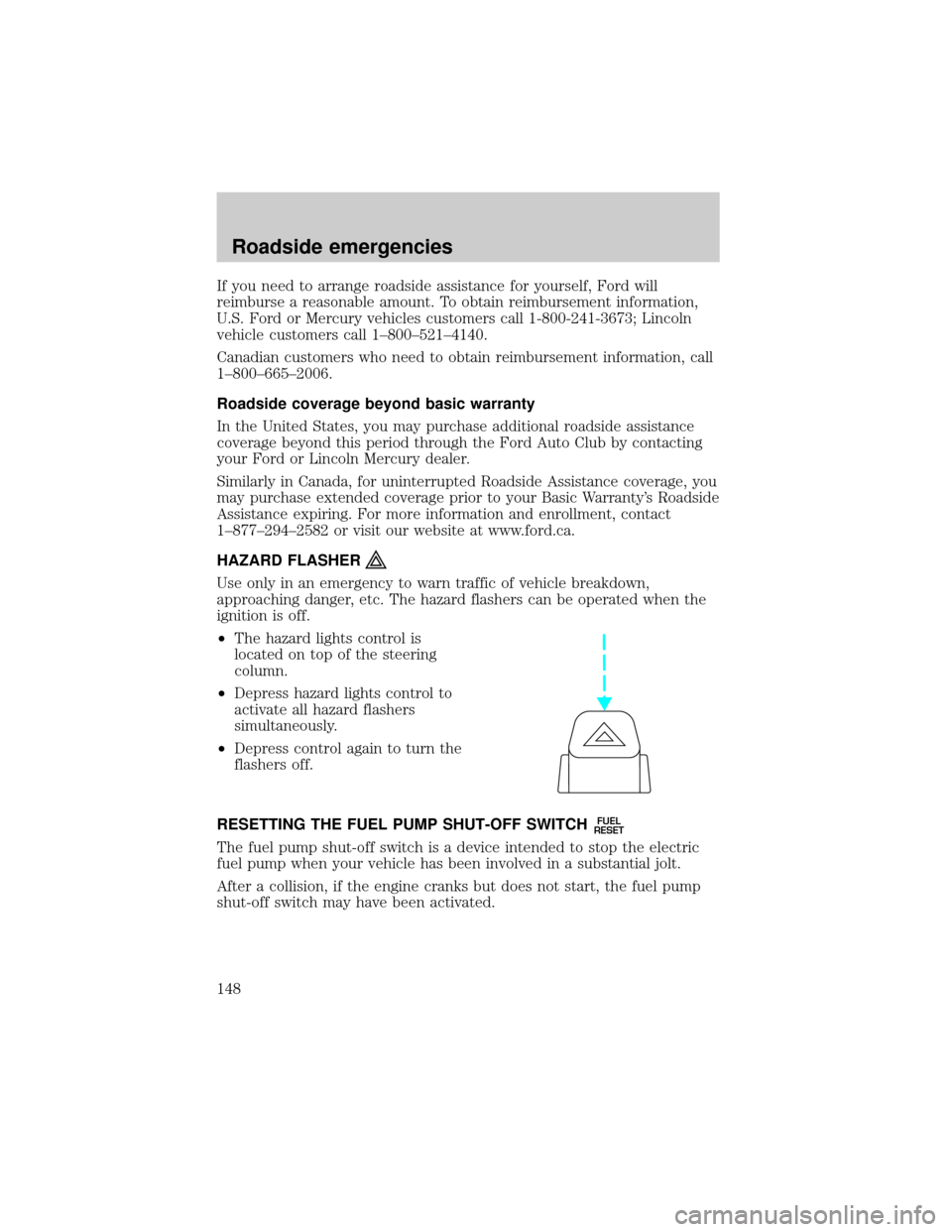
²The hazard lights control is
located on top of the steering
column.
²Depress hazard lights control to
activate all hazard flashers
simultaneously.
²Depress control again to turn the
flashers off.
RESETTING THE FUEL PUMP SHUT-OFF SWITCH
FUEL
RESET
The fuel pump shut-off switch is a device intended to stop the electric
fuel pump when your vehicle has been involved in a substantial jolt.
After a collision, if the engine cranks but does not start, the fuel pump
shut-off switch may have been activated.
Roadside emergencies
148
Page 151 of 248
Passenger compartment fuse panel
The fuse panel is located below and to the left of the steering wheel by
the brake pedal. Remove the panel cover to access the fuses.
To remove a fuse use the fuse puller tool provided on the fuse panel cover.
The fuses are coded as follows.
Fuse/Relay
LocationFuse Amp
RatingPassenger Compartment Fuse Panel
Description
1 25A Radio, Amplifier, I/P fuse 31
2 5A Powertrain Control Module (PCM),
Instrument Cluster, Electronic Automatic
Temperature Control (EATC), Overhead
Trip Computer Module (OTC), Navigation
Module, Clock
3 20A Cigar Lighter, Data Link Connector
4 7.5A Mirrors, Seats, Pedals, (memory)
FUSE1 12 22
21323
617 27
718 28
819 29
930
20
31 21 11 10
RELAY
5 RELAY
4 RELAY
3 RELAY
2 RELAY
1
31424
41525
51626
Roadside emergencies
151
Page 157 of 248

CHANGING THE TIRES
If you get a flat tire while driving, do not apply the brake heavily.
Instead, gradually decrease your speed. Hold the steering wheel firmly
and slowly move to a safe place on the side of the road.
Spare tire information
Your vehicle is equipped with a spare tire that may be used as a spare or
a regular tire. The spare is identical to the other tires on your vehicle.
Location of the spare tire and tools
The spare tire and tools for your vehicle are stowed in the following
locations:
Item Location
Spare tire Under the vehicle, just forward of
the rear bumper
Jack, wheel nut wrench,
instructionsBehind the access panel located
behind the rear seat
Jack handle On top of the radiator support at
the front of the engine
compartment
Lock In the glove compartment
Removing the jack and tools
1. Locate the access panel behind the passenger rear seat.
2. Remove the jack by turning the thumbwheel counterclockwise to
relieve tension against the stowage bracket.
3. Remove small end of lug wrench from the small pouch in the bottom
of jack tray.
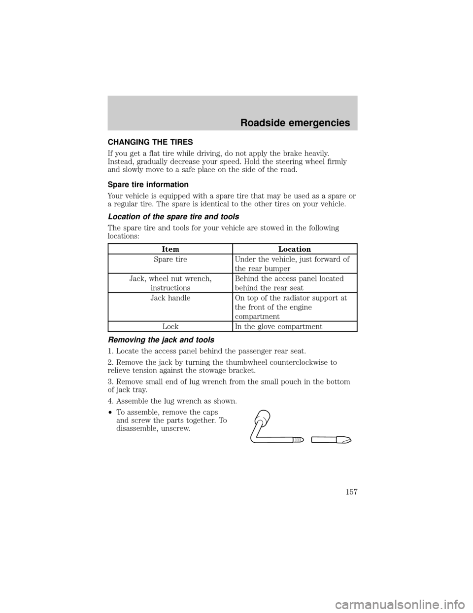
4. Assemble the lug wrench as shown.
²To assemble, remove the caps
and screw the parts together. To
disassemble, unscrew.
Roadside emergencies
157
Page 170 of 248
IDENTIFYING COMPONENTS IN THE ENGINE COMPARTMENT
5.4L 4V V8 engine
1. Battery
2. Automatic transmission fluid dipstick
3. Engine oil filler cap
4. Power steering fluid reservoir
5. Engine oil dipstick
6. Brake fluid reservoir
7. Power distribution box
8. Air filter assembly
9. Engine coolant reservoir
10. Windshield washer fluid reservoir
109
123456
8
7
Maintenance and care
170
Page 181 of 248

How fail-safe cooling works
If the engine begins to overheat:
²the engine coolant temperature
gauge will move to the red (hot)
area.
²the
and thesymbol
will illuminate.
²theService Engine Soon
indicator light will illuminate.
If the engine reaches a preset over-temperature condition, the engine
will automatically switch to alternating cylinder operation. Each disabled
cylinder acts as an air pump and cools the engine.
When this occurs the vehicle will still operate. However:
²the engine power will be limited.
²the air conditioning system will be disabled.
Continued operation will increase the engine temperature:
²the engine will completely shut down.
²steering and braking effort will increase.
Once the engine temperature cools, the engine can be re-started. Take
your vehicle to a service facility as soon as possible to minimize engine
damage.
When fail-safe mode is activated
You have limited engine power when in the fail-safe mode, so drive the
vehicle with caution. The vehicle will not be able to maintain high speed
operation and the engine will run rough. Remember that the engine is
capable of completely shutting down automatically to prevent engine
damage, therefore:
1. Pull off the road as soon as safely possible and turn off the engine.
2. Arrange for the vehicle to be taken to a service facility.
3. If this is not possible, wait a short period for the engine to cool.
4. Check the coolant level and replenish if low.
Never remove the coolant reservoir cap while the engine is
running or hot.
C
H
Maintenance and care
181