Page 75 of 248
The tonneau cover can be operated
by the following:
²overhead console button
²key fob button
²keyless entry key pad
²manually
The Overhead console button and
Keyless entry pad features will only
operate the tonneau cover with the
vehicle in P (Park) or N (Neutral),
the ignition in any position and both
tailgate dual doors must be closed.
The Key fob feature will only operate the tonneau cover with the ignition
in any position except RUN.
NOTE:The instrument panel door ajar light will illuminate when the
tonneau cover is in the open position.
To open the cover from the Overhead console:
Refer toOverhead controlsin this section.
To open the cover with the Key fob:
Refer toRemote Entry Systemin this section.
To open the cover with the Keyless entry pad:
Refer toKeyless Entry Systemin this section.
Controls and features
75
Page 133 of 248

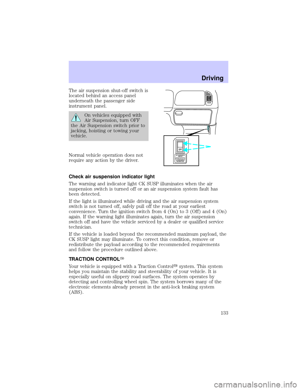
The air suspension shut-off switch is
located behind an access panel
underneath the passenger side
instrument panel.
On vehicles equipped with
Air Suspension, turn OFF
the Air Suspension switch prior to
jacking, hoisting or towing your
vehicle.
Normal vehicle operation does not
require any action by the driver.
Check air suspension indicator light
The warning and indicator light CK SUSP illuminates when the air
suspension switch is turned off or an air suspension system fault has
been detected.
If the light is illuminated while driving and the air suspension system
switch is not turned off, safely pull off the road at your earliest
convenience. Turn the ignition switch from 4 (On) to 3 (Off) and 4 (On)
again. If the warning light illuminates again, turn the air suspension
switch off and have the vehicle serviced by a dealer or qualified service
technician.
If the vehicle is loaded beyond the recommended maximum payload, the
CK SUSP light may illuminate. To correct this condition, remove or
redistribute the payload according to the recommended requirements
and follow the procedure outlined above.
TRACTION CONTROLY
Your vehicle is equipped with a Traction Controlysystem. This system
helps you maintain the stability and steerability of your vehicle. It is
especially useful on slippery road surfaces. The system operates by
detecting and controlling wheel spin. The system borrows many of the
electronic elements already present in the anti-lock braking system
(ABS).
AIR SUSPENSION
SWITCH
INTERRUPTEUR DE
LA SUSPENSION
PNEUMATIQUE
OFF
Driving
133
Page 142 of 248

²Thoroughly prepare your vehicle for towing. Refer toPreparing to
towin this chapter.
²Use extra caution when driving while trailer towing. Refer toDriving
while you towin this chapter.
²Service your vehicle more frequently if you tow a trailer. Refer to the
severe duty schedule in the scheduled maintenance guide.
²Do not tow a trailer until your vehicle has been driven at least 800 km
(500 miles).
²Refer to the instructions included with towing accessories for the
proper installation and adjustment specifications.
Your vehicle is pre-wired for trailer towing. An electrical connector is
provided under the instrument panel for installing a customer-supplied
electric brake controller. Another electrical connector is provided at the
hitch. This connector provides power to the trailer for taillamps, stop
and turn lamps, back up lamps, battery charge, electric brakes (when a
customer provided controller is installed) and ground. The kit included
with your vehicle provides you with adaptors to attach the brake
controller and convert the hitch connector for Class I trailer usage.
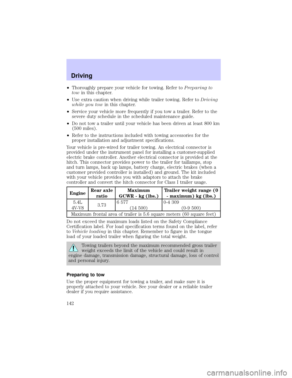
EngineRear axle
ratioMaximum
GCWR - kg (lbs.)Trailer weight range (0
- maximum) kg (lbs.)
5.4L
4V-V83.736 577
(14 500)0-4 309
(0-9 500)
Maximum frontal area of trailer is 5.6 square meters (60 square feet)
Do not exceed the maximum loads listed on the Safety Compliance
Certification label. For load specification terms found on the label, refer
toVehicle loadingin this chapter. Remember to figure in the tongue
load of your loaded trailer when figuring the total weight.
Towing trailers beyond the maximum recommended gross trailer
weight exceeds the limit of the vehicle and could result in
engine damage, transmission damage, structural damage, loss of control
and personal injury.
Preparing to tow
Use the proper equipment for towing a trailer, and make sure it is
properly attached to your vehicle. See your dealer or a reliable trailer
dealer if you require assistance.
Driving
142
Page 151 of 248
Passenger compartment fuse panel
The fuse panel is located below and to the left of the steering wheel by
the brake pedal. Remove the panel cover to access the fuses.
To remove a fuse use the fuse puller tool provided on the fuse panel cover.
The fuses are coded as follows.
Fuse/Relay
LocationFuse Amp
RatingPassenger Compartment Fuse Panel
Description
1 25A Radio, Amplifier, I/P fuse 31
2 5A Powertrain Control Module (PCM),
Instrument Cluster, Electronic Automatic
Temperature Control (EATC), Overhead
Trip Computer Module (OTC), Navigation
Module, Clock
3 20A Cigar Lighter, Data Link Connector
4 7.5A Mirrors, Seats, Pedals, (memory)
FUSE1 12 22
21323
617 27
718 28
819 29
930
20
31 21 11 10
RELAY
5 RELAY
4 RELAY
3 RELAY
2 RELAY
1
31424
41525
51626
Roadside emergencies
151
Page 152 of 248

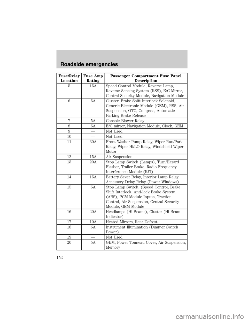
Fuse/Relay
LocationFuse Amp
RatingPassenger Compartment Fuse Panel
Description
5 15A Speed Control Module, Reverse Lamp,
Reverse Sensing System (RSS), E/C Mirror,
Central Security Module, Navigation Module
6 5A Cluster, Brake Shift Interlock Solenoid,
Generic Electronic Module (GEM), RSS, Air
Suspension, OTC, Compass, Automatic
Parking Brake Release
7 5A Console Blower Relay
8 5A E/C mirror, Navigation Module, Clock, GEM
9 Ð Not Used
10 Ð Not Used
11 30A Front Washer Pump Relay, Wiper Run/Park
Relay, Wiper Hi/LO Relay, Windshield Wiper
Motor
12 15A Air Suspension
13 20A Stop Lamp Switch (Lamps), Turn/Hazard
Flasher, Trailer Brake, Radio Frequency
Interference Module (RFI)
14 15A Battery Saver Relay, Interior Lamp Relay,
Accessory Delay Relay (Power Windows)
15 5A Stop Lamp Switch, (Speed Control, Brake
Shift Interlock, Anti-lock Brake System
(ABS), PCM Module Inputs, Traction
Control, Air Suspension, Central Security
Module, GEM Module
16 20A Headlamps (Hi Beams), Cluster (Hi Beam
Indicator)
17 10A Heated Mirrors, Rear Defrost
18 5A Instrument Illumination (Dimmer Switch
Power)
19 Ð Not Used
20 5A GEM, Power Tonneau Cover, Air Suspension,
Memory
Roadside emergencies
152
Page 153 of 248

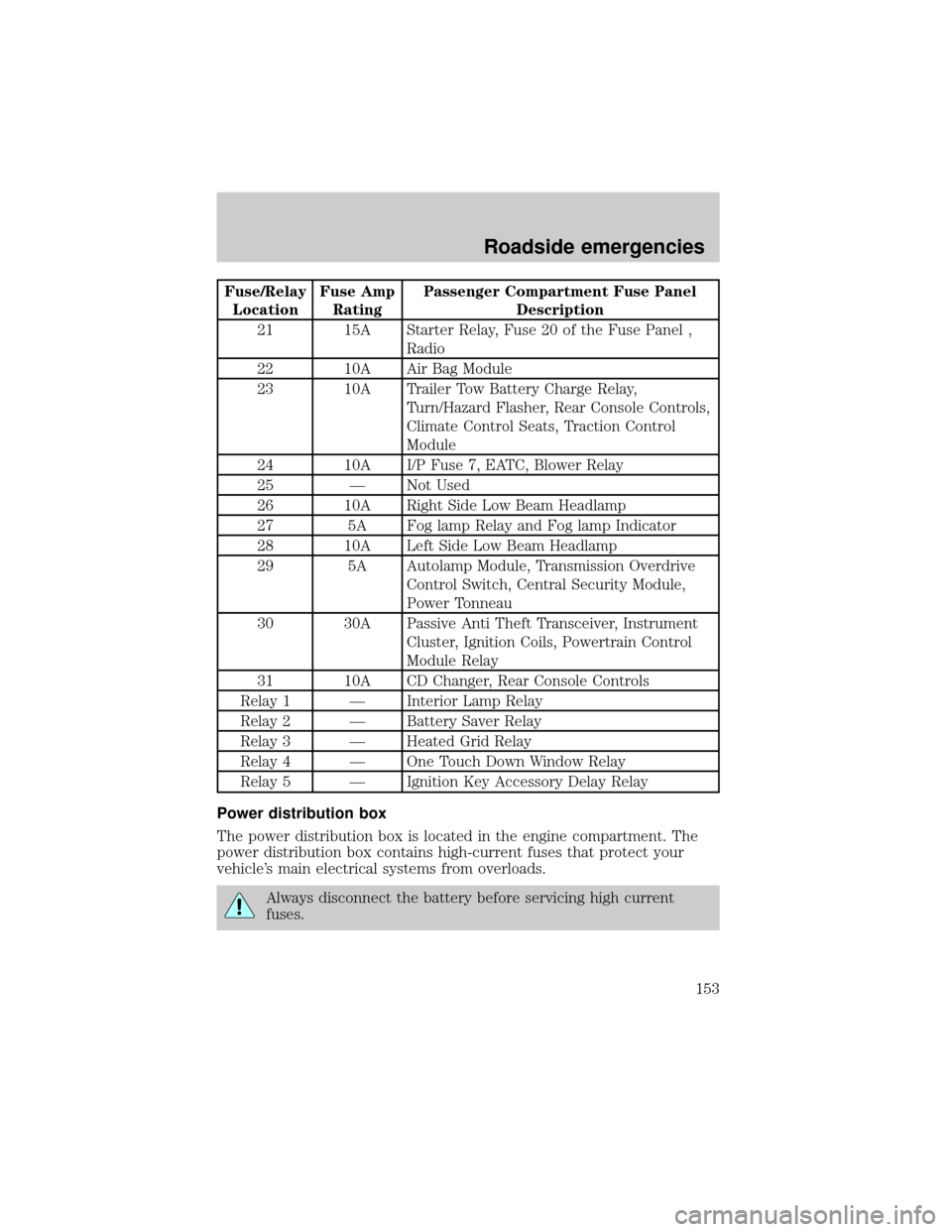
Fuse/Relay
LocationFuse Amp
RatingPassenger Compartment Fuse Panel
Description
21 15A Starter Relay, Fuse 20 of the Fuse Panel ,
Radio
22 10A Air Bag Module
23 10A Trailer Tow Battery Charge Relay,
Turn/Hazard Flasher, Rear Console Controls,
Climate Control Seats, Traction Control
Module
24 10A I/P Fuse 7, EATC, Blower Relay
25 Ð Not Used
26 10A Right Side Low Beam Headlamp
27 5A Fog lamp Relay and Fog lamp Indicator
28 10A Left Side Low Beam Headlamp
29 5A Autolamp Module, Transmission Overdrive
Control Switch, Central Security Module,
Power Tonneau
30 30A Passive Anti Theft Transceiver, Instrument
Cluster, Ignition Coils, Powertrain Control
Module Relay
31 10A CD Changer, Rear Console Controls
Relay 1 Ð Interior Lamp Relay
Relay 2 Ð Battery Saver Relay
Relay 3 Ð Heated Grid Relay
Relay 4 Ð One Touch Down Window Relay
Relay 5 Ð Ignition Key Accessory Delay Relay
Power distribution box
The power distribution box is located in the engine compartment. The
power distribution box contains high-current fuses that protect your
vehicle's main electrical systems from overloads.
Always disconnect the battery before servicing high current
fuses.
Roadside emergencies
153
Page 169 of 248
Do not start your engine with the air cleaner removed and do
not remove it while the engine is running.
OPENING THE HOOD
1. Inside the vehicle, pull the hood
release handle located under the
bottom left corner of the instrument
panel.
2. Go to the front of the vehicle and
release the auxiliary latch located
under the front of the hood, just
above the passenger side headlamp.
Slide the yellow handle to release
the auxiliary latch.
3. Lift the hood until the lift
cylinders hold it open.
BRAKE
HOOD
Maintenance and care
169
Page 209 of 248
USING THE RIGHT BULBS
Replacement bulbs are specified in the chart below. Headlamp bulbs
must be marked with an authorized ªD.O.T.º for North America and an
ªEº for Europe to assure lamp performance, light brightness and pattern
and safe visibility. The correct bulbs will not damage the lamp assembly
or void the lamp assembly warranty and will provide quality bulb burn
time.
Function Number of bulbs Trade number
Headlamps 2 9007
Front park/turn lamps 2 3157 AK (amber)
Front sidemarker 2 194 AK (amber)
Foglamps 2 880
Dome/map lamps 2 579
Turn/tail/brake lamps 2 3157K
Rear cornering lamp 2 921
Backup lamp 2 921
License lamp 2 168
High-mount brake
lamp3 906
All replacement bulbs are clear in color except where noted.
To replace all instrument panel lights - see your dealer
Maintenance and care
209