2002 JEEP LIBERTY window
[x] Cancel search: windowPage 1163 of 1803
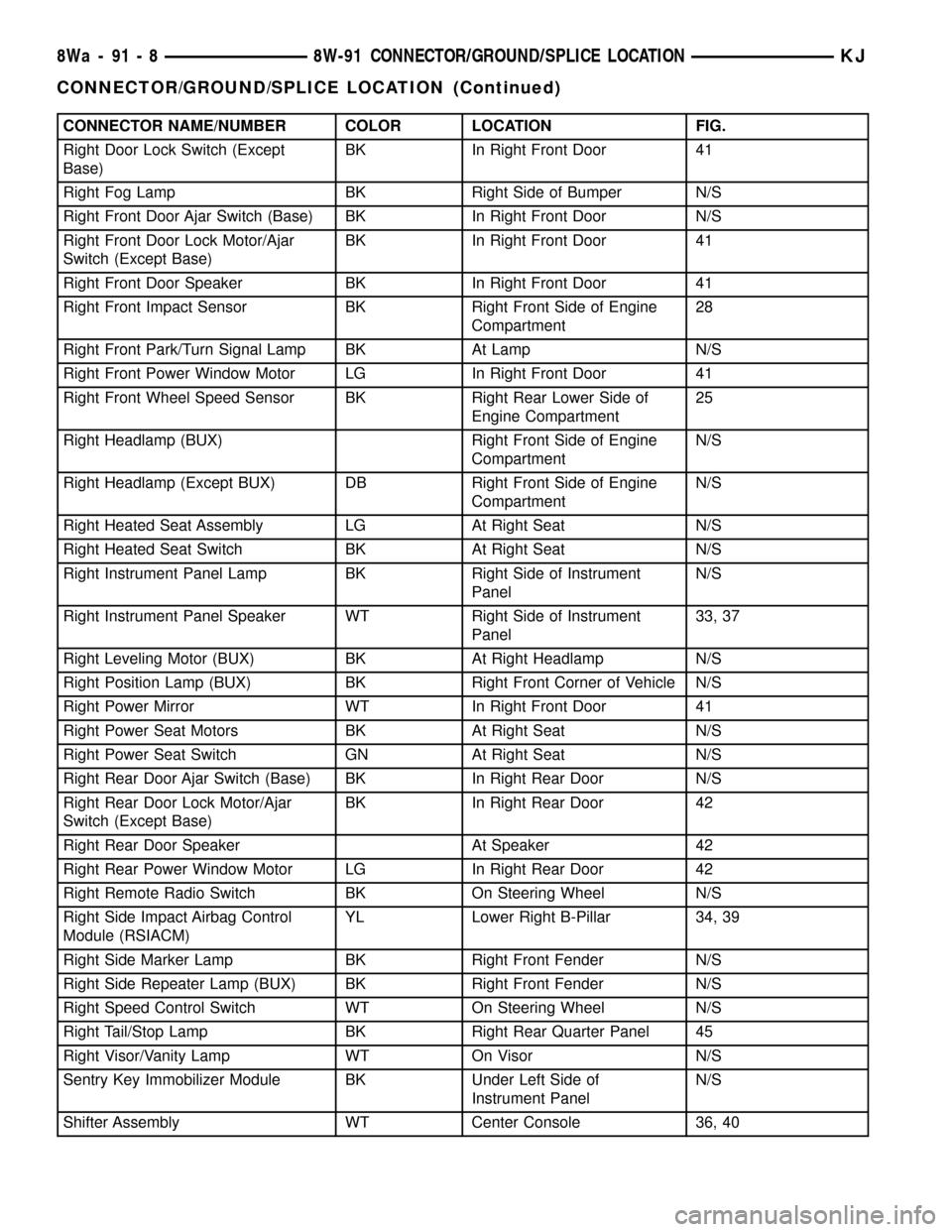
CONNECTOR NAME/NUMBER COLOR LOCATION FIG.
Right Door Lock Switch (Except
Base)BK In Right Front Door 41
Right Fog Lamp BK Right Side of Bumper N/S
Right Front Door Ajar Switch (Base) BK In Right Front Door N/S
Right Front Door Lock Motor/Ajar
Switch (Except Base)BK In Right Front Door 41
Right Front Door Speaker BK In Right Front Door 41
Right Front Impact Sensor BK Right Front Side of Engine
Compartment28
Right Front Park/Turn Signal Lamp BK At Lamp N/S
Right Front Power Window Motor LG In Right Front Door 41
Right Front Wheel Speed Sensor BK Right Rear Lower Side of
Engine Compartment25
Right Headlamp (BUX) Right Front Side of Engine
CompartmentN/S
Right Headlamp (Except BUX) DB Right Front Side of Engine
CompartmentN/S
Right Heated Seat Assembly LG At Right Seat N/S
Right Heated Seat Switch BK At Right Seat N/S
Right Instrument Panel Lamp BK Right Side of Instrument
PanelN/S
Right Instrument Panel Speaker WT Right Side of Instrument
Panel33, 37
Right Leveling Motor (BUX) BK At Right Headlamp N/S
Right Position Lamp (BUX) BK Right Front Corner of Vehicle N/S
Right Power Mirror WT In Right Front Door 41
Right Power Seat Motors BK At Right Seat N/S
Right Power Seat Switch GN At Right Seat N/S
Right Rear Door Ajar Switch (Base) BK In Right Rear Door N/S
Right Rear Door Lock Motor/Ajar
Switch (Except Base)BK In Right Rear Door 42
Right Rear Door Speaker At Speaker 42
Right Rear Power Window Motor LG In Right Rear Door 42
Right Remote Radio Switch BK On Steering Wheel N/S
Right Side Impact Airbag Control
Module (RSIACM)YL Lower Right B-Pillar 34, 39
Right Side Marker Lamp BK Right Front Fender N/S
Right Side Repeater Lamp (BUX) BK Right Front Fender N/S
Right Speed Control Switch WT On Steering Wheel N/S
Right Tail/Stop Lamp BK Right Rear Quarter Panel 45
Right Visor/Vanity Lamp WT On Visor N/S
Sentry Key Immobilizer Module BK Under Left Side of
Instrument PanelN/S
Shifter Assembly WT Center Console 36, 40
8Wa - 91 - 8 8W-91 CONNECTOR/GROUND/SPLICE LOCATIONKJ
CONNECTOR/GROUND/SPLICE LOCATION (Continued)
Page 1168 of 1803
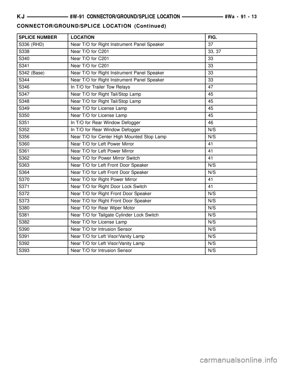
SPLICE NUMBER LOCATION FIG.
S336 (RHD) Near T/O for Right Instrument Panel Speaker 37
S338 Near T/O for C201 33, 37
S340 Near T/O for C201 33
S341 Near T/O for C201 33
S342 (Base) Near T/O for Right Instrument Panel Speaker 33
S344 Near T/O for Right Instrument Panel Speaker 33
S346 In T/O for Trailer Tow Relays 47
S347 Near T/O for Right Tail/Stop Lamp 45
S348 Near T/O for Right Tail/Stop Lamp 45
S349 Near T/O for License Lamp 45
S350 Near T/O for License Lamp 45
S351 In T/O for Rear Window Defogger 46
S352 In T/O for Rear Window Defogger N/S
S356 Near T/O for Center High Mounted Stop Lamp N/S
S360 Near T/O for Left Power Mirror 41
S361 Near T/O for Left Power Mirror 41
S362 Near T/O for Power Mirror Switch 41
S363 Near T/O for Left Front Door Speaker N/S
S364 Near T/O for Left Front Door Speaker N/S
S370 Near T/O for Right Power Mirror 41
S371 Near T/O for Right Door Lock Switch 41
S372 Near T/O for Right Front Door Speaker N/S
S373 Near T/O for Right Front Door Speaker N/S
S380 Near T/O for Rear Wiper Motor N/S
S381 Near T/O for Tailgate Cylinder Lock Switch N/S
S382 Near T/O for License Lamp N/S
S390 Near T/O for Intrusion Sensor N/S
S391 Near T/O for Left Visor/Vanity Lamp N/S
S392 Near T/O for Left Visor/Vanity Lamp N/S
S393 Near T/O for Intrusion Sensor N/S
KJ8W-91 CONNECTOR/GROUND/SPLICE LOCATION8Wa-91-13
CONNECTOR/GROUND/SPLICE LOCATION (Continued)
Page 1355 of 1803
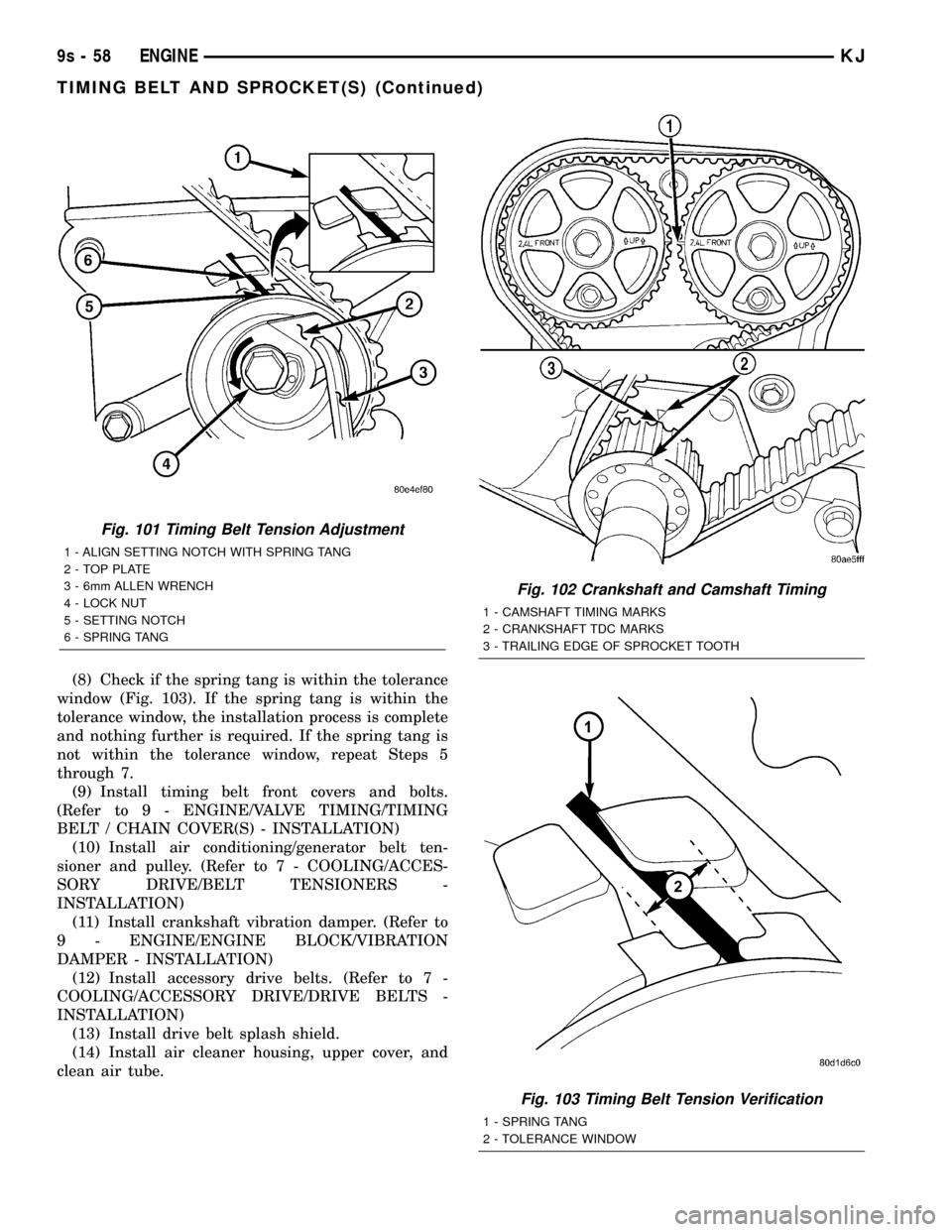
(8) Check if the spring tang is within the tolerance
window (Fig. 103). If the spring tang is within the
tolerance window, the installation process is complete
and nothing further is required. If the spring tang is
not within the tolerance window, repeat Steps 5
through 7.
(9) Install timing belt front covers and bolts.
(Refer to 9 - ENGINE/VALVE TIMING/TIMING
BELT / CHAIN COVER(S) - INSTALLATION)
(10) Install air conditioning/generator belt ten-
sioner and pulley. (Refer to 7 - COOLING/ACCES-
SORY DRIVE/BELT TENSIONERS -
INSTALLATION)
(11) Install crankshaft vibration damper. (Refer to
9 - ENGINE/ENGINE BLOCK/VIBRATION
DAMPER - INSTALLATION)
(12) Install accessory drive belts. (Refer to 7 -
COOLING/ACCESSORY DRIVE/DRIVE BELTS -
INSTALLATION)
(13) Install drive belt splash shield.
(14) Install air cleaner housing, upper cover, and
clean air tube.
Fig. 101 Timing Belt Tension Adjustment
1 - ALIGN SETTING NOTCH WITH SPRING TANG
2 - TOP PLATE
3 - 6mm ALLEN WRENCH
4 - LOCK NUT
5 - SETTING NOTCH
6 - SPRING TANG
Fig. 102 Crankshaft and Camshaft Timing
1 - CAMSHAFT TIMING MARKS
2 - CRANKSHAFT TDC MARKS
3 - TRAILING EDGE OF SPROCKET TOOTH
Fig. 103 Timing Belt Tension Verification
1 - SPRING TANG
2 - TOLERANCE WINDOW
9s - 58 ENGINEKJ
TIMING BELT AND SPROCKET(S) (Continued)
Page 1407 of 1803
REMOVAL
Fuel Tank Draining
WARNING: THE FUEL SYSTEM MAY BE UNDER
CONSTANT FUEL PRESSURE EVEN WITH THE
ENGINE OFF. THIS PRESSURE MUST BE
RELEASED BEFORE SERVICING FUEL TANK.
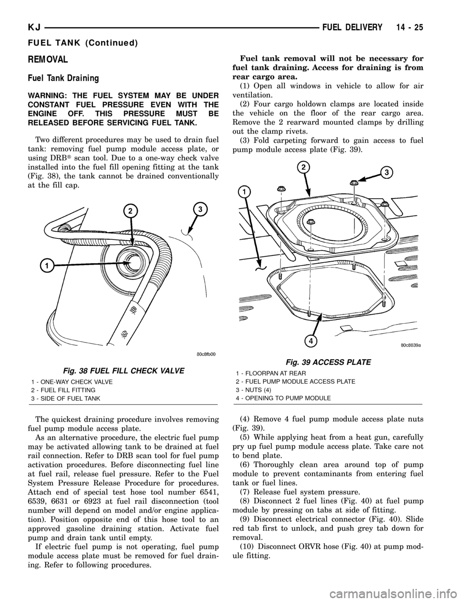
Two different procedures may be used to drain fuel
tank: removing fuel pump module access plate, or
using DRBtscan tool. Due to a one-way check valve
installed into the fuel fill opening fitting at the tank
(Fig. 38), the tank cannot be drained conventionally
at the fill cap.
The quickest draining procedure involves removing
fuel pump module access plate.
As an alternative procedure, the electric fuel pump
may be activated allowing tank to be drained at fuel
rail connection. Refer to DRB scan tool for fuel pump
activation procedures. Before disconnecting fuel line
at fuel rail, release fuel pressure. Refer to the Fuel
System Pressure Release Procedure for procedures.
Attach end of special test hose tool number 6541,
6539, 6631 or 6923 at fuel rail disconnection (tool
number will depend on model and/or engine applica-
tion). Position opposite end of this hose tool to an
approved gasoline draining station. Activate fuel
pump and drain tank until empty.
If electric fuel pump is not operating, fuel pump
module access plate must be removed for fuel drain-
ing. Refer to following procedures.Fuel tank removal will not be necessary for
fuel tank draining. Access for draining is from
rear cargo area.
(1) Open all windows in vehicle to allow for air
ventilation.
(2) Four cargo holdown clamps are located inside
the vehicle on the floor of the rear cargo area.
Remove the 2 rearward mounted clamps by drilling
out the clamp rivets.
(3) Fold carpeting forward to gain access to fuel
pump module access plate (Fig. 39).
(4) Remove 4 fuel pump module access plate nuts
(Fig. 39).
(5) While applying heat from a heat gun, carefully
pry up fuel pump module access plate. Take care not
to bend plate.
(6) Thoroughly clean area around top of pump
module to prevent contaminants from entering fuel
tank or fuel lines.
(7) Release fuel system pressure.
(8) Disconnect 2 fuel lines (Fig. 40) at fuel pump
module by pressing on tabs at side of fitting.
(9) Disconnect electrical connector (Fig. 40). Slide
red tab first to unlock, and push grey tab down for
removal.
(10) Disconnect ORVR hose (Fig. 40) at pump mod-
ule fitting.
Fig. 38 FUEL FILL CHECK VALVE
1 - ONE-WAY CHECK VALVE
2 - FUEL FILL FITTING
3 - SIDE OF FUEL TANK
Fig. 39 ACCESS PLATE
1 - FLOORPAN AT REAR
2 - FUEL PUMP MODULE ACCESS PLATE
3 - NUTS (4)
4 - OPENING TO PUMP MODULE
KJFUEL DELIVERY 14 - 25
FUEL TANK (Continued)
Page 1467 of 1803
DIAGNOSIS AND TESTING
DIAGNOSIS AND TESTING - WATER LEAKS
Water leaks can be caused by poor sealing,
improper body component alignment, body seam
porosity, missing plugs, or blocked drain holes. Cen-
trifugal and gravitational force can cause water to
drip from a location away from the actual leak point,
making leak detection difficult. All body sealing
points should be water tight in normal wet-driving
conditions. Water flowing downward from the front of
the vehicle should not enter the passenger or luggage
compartment. Moving sealing surfaces will not
always seal water tight under all conditions. At
times, side glass or door seals will allow water to
enter the passenger compartment during high pres-
sure washing or hard driving rain (severe) condi-
tions. Overcompensating on door or glass
adjustments to stop a water leak that occurs under
severe conditions can cause premature seal wear and
excessive closing or latching effort. After completing
a repair, water test vehicle to verify leak has stopped
before returning vehicle to use.
VISUAL INSPECTION BEFORE WATER LEAK TESTS
Verify that floor and body plugs are in place, body
drains are clear, and body components are properly
aligned and sealed. If component alignment or seal-
ing is necessary, refer to the appropriate section of
this group for proper procedures.
WATER LEAK TESTS
WARNING: DO NOT USE ELECTRIC SHOP LIGHTS
OR TOOLS IN WATER TEST AREA. PERSONAL
INJURY CAN RESULT.
When the conditions causing a water leak have
been determined, simulate the conditions as closely
as possible.
²If a leak occurs with the vehicle parked in a
steady light rain, flood the leak area with an open-
ended garden hose.
²If a leak occurs while driving at highway speeds
in a steady rain, test the leak area with a reasonable
velocity stream or fan spray of water. Direct the
spray in a direction comparable to actual conditions.
²If a leak occurs when the vehicle is parked on an
incline, hoist the end or side of the vehicle to simu-
late this condition. This method can be used when
the leak occurs when the vehicle accelerates, stops or
turns. If the leak occurs on acceleration, hoist the
front of the vehicle. If the leak occurs when braking,
hoist the back of the vehicle. If the leak occurs on left
turns, hoist the left side of the vehicle. If the leak
occurs on right turns, hoist the right side of the vehi-cle. For hoisting recommendations refer to Group 0,
Lubrication and Maintenance, General Information
section.
WATER LEAK DETECTION
To detect a water leak point-of-entry, do a water
test and watch for water tracks or droplets forming
on the inside of the vehicle. If necessary, remove inte-
rior trim covers or panels to gain visual access to the
leak area. If the hose cannot be positioned without
being held, have someone help do the water test.
Some water leaks must be tested for a considerable
length of time to become apparent. When a leak
appears, find the highest point of the water track or
drop. The highest point usually will show the point of
entry. After leak point has been found, repair the
leak and water test to verify that the leak has
stopped.
Locating the entry point of water that is leaking
into a cavity between panels can be difficult. The
trapped water may splash or run from the cavity,
often at a distance from the entry point. Most water
leaks of this type become apparent after accelerating,
stopping, turning, or when on an incline.
MIRROR INSPECTION METHOD
When a leak point area is visually obstructed, use
a suitable mirror to gain visual access. A mirror can
also be used to deflect light to a limited-access area
to assist in locating a leak point.
BRIGHT LIGHT LEAK TEST METHOD
Some water leaks in the luggage compartment can
be detected without water testing. Position the vehi-
cle in a brightly lit area. From inside the darkened
luggage compartment inspect around seals and body
seams. If necessary, have a helper direct a drop light
over the suspected leak areas around the luggage
compartment. If light is visible through a normally
sealed location, water could enter through the open-
ing.
PRESSURIZED LEAK TEST METHOD
When a water leak into the passenger compart-
ment cannot be detected by water testing, pressurize
the passenger compartment and soap test exterior of
the vehicle. To pressurize the passenger compart-
ment, close all doors and windows, start engine, and
set heater control to high blower in HEAT position. If
engine can not be started, connect a charger to the
battery to ensure adequate voltage to the blower.
With interior pressurized, apply dish detergent solu-
tion to suspected leak area on the exterior of the
vehicle. Apply detergent solution with spray device or
soft bristle brush. If soap bubbles occur at a body
seam, joint, seal or gasket, the leak entry point could
be at that location.
23 - 2 BODYKJ
BODY (Continued)
Page 1476 of 1803
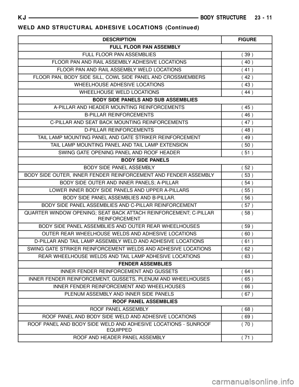
DESCRIPTION FIGURE
FULL FLOOR PAN ASSEMBLY
FULL FLOOR PAN ASSEMBLIES ( 39 )
FLOOR PAN AND RAIL ASSEMBLY ADHESIVE LOCATIONS ( 40 )
FLOOR PAN AND RAIL ASSEMBLY WELD LOCATIONS ( 41 )
FLOOR PAN, BODY SIDE SILL, COWL SIDE PANEL AND CROSSMEMBERS ( 42 )
WHEELHOUSE ADHESIVE LOCATIONS ( 43 )
WHEELHOUSE WELD LOCATIONS ( 44 )
BODY SIDE PANELS AND SUB ASSEMBLIES
A-PILLAR AND HEADER MOUNTING REINFORCEMENTS ( 45 )
B-PILLAR REINFORCEMENTS ( 46 )
C-PILLAR AND SEAT BACK MOUNTING REINFORCEMENTS ( 47 )
D-PILLAR REINFORCEMENTS ( 48 )
TAIL LAMP MOUNTING PANEL AND GATE STRIKER REINFORCEMENT ( 49 )
TAIL LAMP MOUNTING PANEL AND TAIL LAMP EXTENSION ( 50 )
SWING GATE OPENING PANEL AND ROOF HEADER ( 51 )
BODY SIDE PANELS
BODY SIDE PANEL ASSEMBLY ( 52 )
BODY SIDE OUTER, INNER FENDER REINFORCEMENT AND FENDER ASSEMBLY ( 53 )
BODY SIDE OUTER AND INNER PANELS; A-PILLAR ( 54 )
LOWER INNER BODY SIDE PANELS AND UPPER A-PILLARS ( 55 )
BODY SIDE PANEL ASSEMBLIES AND B-PILLAR. ( 56 )
BODY SIDE PANEL ASSEMBLIES AND C-PILLAR REINFORCEMENT ( 57 )
QUARTER WINDOW OPENING; SEAT BACK ATTACH REINFORCEMENT; C-PILLAR
REINFORCEMENT(58)
BODY SIDE PANEL ASSEMBLIES AND OUTER REAR WHEELHOUSES ( 59 )
OUTER REAR WHEELHOUSE WELDS AND ADHESIVE LOCATIONS ( 60 )
D-PILLAR AND TAIL LAMP ASSEMBLY WELD AND ADHESIVE LOCATIONS ( 61 )
SWING GATE STRIKER REINFORCEMENT WELDS AND ADHESIVE LOCATIONS ( 62 )
REAR WHEELHOUSE WELDS AND TAIL LAMP ADHESIVE LOCATIONS ( 63 )
FENDER ASSEMBLIES
INNER FENDER REINFORCEMENT AND GUSSETS ( 64 )
INNER FENDER REINFORCEMENT, GUSSETS, PLENUM AND WHEELHOUSES ( 65 )
INNER FENDER REINFORCEMENT AND WHEELHOUSES ( 66 )
PLENUM ASSEMBLY AND INNER SIDE PANELS ( 67 )
ROOF PANEL ASSEMBLIES
ROOF PANEL ASSEMBLY ( 68 )
ROOF PANEL AND BODY SIDE WELD AND ADHESIVE LOCATIONS ( 69 )
ROOF PANEL AND BODY SIDE WELD AND ADHESIVE LOCATIONS - SUNROOF
EQUIPPED(70)
ROOF AND HEADER PANEL ASSEMBLY ( 71 )
KJBODY STRUCTURE 23 - 11
WELD AND STRUCTURAL ADHESIVE LOCATIONS (Continued)
Page 1532 of 1803
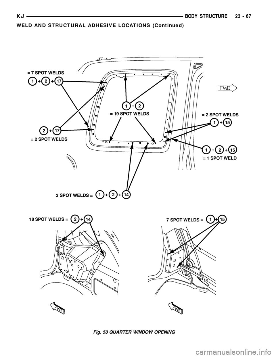
Fig. 58 QUARTER WINDOW OPENING
KJBODY STRUCTURE 23 - 67
WELD AND STRUCTURAL ADHESIVE LOCATIONS (Continued)
Page 1586 of 1803
DOOR - FRONT
TABLE OF CONTENTS
page page
CHECK STRAP
REMOVAL............................121
INSTALLATION........................121
DOOR
REMOVAL............................122
INSTALLATION........................122
DOOR GLASS
REMOVAL............................122
INSTALLATION........................122
EXTERIOR HANDLE
REMOVAL............................123
INSTALLATION........................123
GLASS RUN CHANNEL
REMOVAL............................123
INSTALLATION........................123
HINGE
REMOVAL............................123
INSTALLATION........................123
LATCH
REMOVAL............................124
INSTALLATION........................124ADJUSTMENTS
ADJUSTMENT.......................124
LATCH STRIKER
REMOVAL............................124
INSTALLATION........................124
LOCK CYLINDER
REMOVAL............................125
INSTALLATION........................125
TRIM PANEL
REMOVAL............................125
INSTALLATION........................126
WATERDAM
REMOVAL............................126
INSTALLATION........................126
WINDOW REGULATOR - MANUAL
REMOVAL............................126
INSTALLATION........................126
WINDOW REGULATOR - ELECTRIC
REMOVAL............................126
INSTALLATION........................126
CHECK STRAP
REMOVAL
(1) Remove the waterdam. (Refer to 23 - BODY/
DOOR - FRONT/WATERDAM - REMOVAL)
(2) Remove screws attaching door check to A-pillar.
(3) Remove the two nuts and remove the door
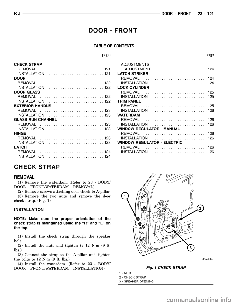
check strap. (Fig. 1)
INSTALLATION
NOTE: Make sure the proper orientation of the
check strap is maintained using the ªRº and ªLº on
the top.
(1) Install the check strap through the speaker
hole.
(2) Install the nuts and tighten to 12 N´m (9 ft.
lbs.).
(3) Connect the strap to the A-pillar and tighten
the bolts to 12 N´m (9 ft. lbs.).
(4) Install the waterdam. (Refer to 23 - BODY/
DOOR - FRONT/WATERDAM - INSTALLATION)
Fig. 1 CHECK STRAP
1 - NUTS
2 - CHECK STRAP
3 - SPEAKER OPENING
KJDOOR - FRONT 23 - 121