2002 JEEP LIBERTY Engine 3.7L
[x] Cancel search: Engine 3.7LPage 398 of 1803

(3) Position ignition coil into cylinder head opening
and push onto spark plug. Do this while guiding coil
base over mounting stud.
(4) Install coil mounting stud nut. Refer to torque
specifications.(5) Connect electrical connector to coil by snapping
into position.
(6) If necessary, install throttle body air tube or
box.
KNOCK SENSOR
DESCRIPTION
The 2 knock sensors are bolted into the cylinder
block under the intake manifold. The sensors are
used only with the 3.7L engine.
OPERATION
Two knock sensors are used on the 3.7L V-6
engine; one for each cylinder bank. When the knock
sensor detects a knock in one of the cylinders on the
corresponding bank, it sends an input signal to the
Powertrain Control Module (PCM). In response, the
PCM retards ignition timing for all cylinders by a
scheduled amount.
Knock sensors contain a piezoelectric material
which constantly vibrates and sends an input voltage
(signal) to the PCM while the engine operates. As the
intensity of the crystal's vibration increases, the
knock sensor output voltage also increases.
The voltage signal produced by the knock sensor
increases with the amplitude of vibration. The PCM
receives the knock sensor voltage signal as an input.
If the signal rises above a predetermined level, the
PCM will store that value in memory and retard
ignition timing to reduce engine knock. If the knock
sensor voltage exceeds a preset value, the PCM
retards ignition timing for all cylinders. It is not a
selective cylinder retard.
The PCM ignores knock sensor input during engine
idle conditions. Once the engine speed exceeds a
specified value, knock retard is allowed.
Knock retard uses its own short term and long
term memory program.
Long term memory stores previous detonation
information in its battery-backed RAM. The maxi-
mum authority that long term memory has over tim-
ing retard can be calibrated.
Short term memory is allowed to retard timing up
to a preset amount under all operating conditions (as
long as rpm is above the minimum rpm) except at
Wide Open Throttle (WOT). The PCM, using short
term memory, can respond quickly to retard timing
when engine knock is detected. Short term memory
is lost any time the ignition key is turned off.
Fig. 18 IGNITION COIL LOCATION - 3.7L
1 - IGNITION COIL
2 - COIL MOUNTING NUT
Fig. 19 IGNITION COIL - 3.7L
1 - O-RING
2 - IGNITION COIL
3 - ELECTRICAL CONNECTOR
KJIGNITION CONTROL 8I - 11
IGNITION COIL (Continued)
Page 674 of 1803

SPEED CONTROL
TABLE OF CONTENTS
page page
SPEED CONTROL
DESCRIPTION..........................1
OPERATION............................1
DIAGNOSIS AND TESTING - ROAD TEST.....2
SPECIFICATIONS
TORQUE - SPEED CONTROL.............2
CABLE
DESCRIPTION..........................3
OPERATION............................3
REMOVAL - 3.7L.........................3
INSTALLATION - 3.7L.....................4
SERVO
DESCRIPTION..........................4
OPERATION............................4REMOVAL.............................4
INSTALLATION..........................5
SWITCH
DESCRIPTION..........................5
OPERATION............................5
REMOVAL.............................6
INSTALLATION..........................6
VACUUM RESERVOIR
DESCRIPTION..........................7
OPERATION............................7
DIAGNOSIS AND TESTING - VACUUM
RESERVOIR..........................7
REMOVAL.............................7
INSTALLATION..........................8
SPEED CONTROL
DESCRIPTION
The speed control system is electronically con-
trolled and vacuum operated. Electronic control of
the speed control system is integrated into the Pow-
ertrain Control Module (PCM). The controls consist
of two steering wheel mounted switches. The
switches are labeled: ON/OFF, RES/ACCEL, SET,
COAST, and CANCEL.
The system is designed to operate at speeds above
30 mph (50 km/h).
WARNING: THE USE OF SPEED CONTROL IS NOT
RECOMMENDED WHEN DRIVING CONDITIONS DO
NOT PERMIT MAINTAINING A CONSTANT SPEED,
SUCH AS IN HEAVY TRAFFIC OR ON ROADS THAT
ARE WINDING, ICY, SNOW COVERED, OR SLIP-
PERY.
OPERATION
When speed control is selected by depressing the
ON switch, the PCM allows a set speed to be stored
in PCM RAM for speed control. To store a set speed,
depress the SET switch while the vehicle is moving
at a speed between 35 and 85 mph. In order for the
speed control to engage, the brakes cannot be
applied, nor can the gear selector be indicating the
transmission is in Park or Neutral.
The speed control can be disengaged manually by:
²Stepping on the brake pedal
²Depressing the OFF switch²Depressing the CANCEL switch.
²Depressing the clutch pedal (if equipped).
NOTE: Depressing the OFF switch or turning off the
ignition switch will erase the set speed stored in
the PCM.
For added safety, the speed control system is pro-
grammed to disengage for any of the following condi-
tions:
²An indication of Park or Neutral
²A rapid increase rpm (indicates that the clutch
has been disengaged)
²Excessive engine rpm (indicates that the trans-
mission may be in a low gear)
²The speed signal increases at a rate of 10 mph
per second (indicates that the coefficient of friction
between the road surface and tires is extremely low)
²The speed signal decreases at a rate of 10 mph
per second (indicates that the vehicle may have
decelerated at an extremely high rate)
Once the speed control has been disengaged,
depressing the RES/ACCEL switch (when speed is
greater than 30 mph) restores the vehicle to the tar-
get speed that was stored in the PCM.
While the speed control is engaged, the driver can
increase the vehicle speed by depressing the RES/AC-
CEL switch. The new target speed is stored in the
PCM when the RES/ACCEL is released. The PCM
also has a9tap-up9feature in which vehicle speed
increases at a rate of approximately 2 mph for each
momentary switch activation of the RES/ACCEL
switch.
KJSPEED CONTROL 8P - 1
Page 677 of 1803

(6) Slide speed control cable plastic mount towards
right of vehicle to remove cable from throttle body
bracket (Fig. 4).
(7) Remove servo cable from servo. Refer to Servo
Removal/Installation.
INSTALLATION - 3.7L
(1) Install end of cable to speed control servo.
Refer to Servo Removal/Installation.
(2) Slide speed control cable plastic mount into
throttle body bracket.
(3) Install speed control cable connector onto throt-
tle body bellcrank pin (push rearward to snap into
location).
(4) Slide throttle (accelerator) cable plastic mount
into throttle body bracket. Continue sliding until
cable release tab is aligned to hole in throttle body
mounting bracket.
(5) While holding throttle to wide open position,
place throttle cable pin into throttle body bellcrank.
(6) Install air filter resonator box to throttle body.
(7) Connect negative battery cable at battery.
(8) Before starting engine, operate accelerator
pedal to check for any binding.
SERVO
DESCRIPTION
The servo unit consists of a solenoid valve body,
and a vacuum chamber. The solenoid valve body con-
tains three solenoids:²Vacuum
²Vent
²Dump
The vacuum chamber contains a diaphragm with a
cable attached to control the throttle linkage.
OPERATION
The Powertrain Control Module (PCM) controls the
solenoid valve body. The solenoid valve body controls
the application and release of vacuum to the dia-
phragm of the vacuum servo. The servo unit cannot
be repaired and is serviced only as a complete assem-
bly.
Power is supplied to the servo's by the PCM
through the brake switch. The PCM controls the
ground path for the vacuum and vent solenoids.
The dump solenoid is energized anytime it receives
power. If power to the dump solenoid is interrupted,
the solenoid dumps vacuum in the servo. This pro-
vides a safety backup to the vent and vacuum sole-
noids.
The vacuum and vent solenoids must be grounded
at the PCM to operate. When the PCM grounds the
vacuum servo solenoid, the solenoid allows vacuum
to enter the servo and pull open the throttle plate
using the cable. When the PCM breaks the ground,
the solenoid closes and no more vacuum is allowed to
enter the servo. The PCM also operates the vent sole-
noid via ground. The vent solenoid opens and closes a
passage to bleed or hold vacuum in the servo as
required.
The PCM duty cycles the vacuum and vent sole-
noids to maintain the set speed, or to accelerate and
decelerate the vehicle. To increase throttle opening,
the PCM grounds the vacuum and vent solenoids. To
decrease throttle opening, the PCM removes the
grounds from the vacuum and vent solenoids. When
the brake is released, if vehicle speed exceeds 30
mph to resume, 35 mph to set, and the RES/ACCEL
switch has been depressed, ground for the vent and
vacuum circuits is restored.
REMOVAL
(1) Disconnect negative battery cable at battery.
(2) Disconnect vacuum line at servo (Fig. 5).
(3) Disconnect electrical connector at servo (Fig. 5).
(4) Remove coolant bottle nuts/bolts. Position bot-
tle forward a few inches.
(5) Disconnect servo cable at throttle body. Refer to
servo Cable Removal/Installation.
(6) Remove servo bracket mounting nuts (Fig. 5).
(7) Remove 2 mounting nuts holding servo cable
sleeve to bracket (Fig. 6).
(8) Pull speed control cable sleeve and servo away
from servo mounting bracket to expose cable retain-
ing clip (Fig. 6) and remove clip. Note: The servo
Fig. 4 SPEED CONTROL CABLE AT BRACKET
1 - THROTTLE CABLE BRACKET
2 - PLASTIC CABLE MOUNT
3 - SPEED CONTROL CABLE
8P - 4 SPEED CONTROLKJ
CABLE (Continued)
Page 1057 of 1803

Component Page
C316 (Built-Up-Export).............. 8Wa-80-46
C316 (Built-Up-Export).............. 8Wa-80-46
C317 (Except Built-Up-Export)........ 8Wa-80-47
C317 (Except Built-Up-Export)........ 8Wa-80-47
Cabin Heater (Diesel)............... 8Wa-80-47
Camshaft Position Sensor (2.4L)....... 8Wa-80-47
Camshaft Position Sensor (3.7L)....... 8Wa-80-47
Camshaft Position Sensor (Diesel)...... 8Wa-80-48
Capacitor......................... 8Wa-80-48
Cargo Lamp (Except Base)........... 8Wa-80-48
CD Changer...................... 8Wa-80-48
Center High Mounted Stop Lamp...... 8Wa-80-49
Cigar Lighter..................... 8Wa-80-49
Clockspring C1.................... 8Wa-80-49
Clockspring C2.................... 8Wa-80-49
Clockspring C3.................... 8Wa-80-49
Clutch Interlock Switch (M/T)......... 8Wa-80-50
Coil On Plug No. 1 (3.7L)............ 8Wa-80-50
Coil On Plug No. 2 (3.7L)............ 8Wa-80-50
Coil On Plug No. 3 (3.7L)............ 8Wa-80-50
Coil On Plug No. 4 (3.7L)............ 8Wa-80-50
Coil On Plug No. 5 (3.7L)............ 8Wa-80-51
Coil On Plug No. 6 (3.7L)............ 8Wa-80-51
Coil Rail (2.4L).................... 8Wa-80-51
Compass Mini-Trip Computer
(Premium)...................... 8Wa-80-51
Controller Antilock Brake............ 8Wa-80-52
Crankshaft Position Sensor (2.4L)...... 8Wa-80-52
Crankshaft Position Sensor (3.7L)...... 8Wa-80-52
Crankshaft Position Sensor (Diesel).... 8Wa-80-53
Data Link Connector................ 8Wa-80-53
Diagnostic Junction Port............. 8Wa-80-53
Dome Lamp (Base)................. 8Wa-80-54
Driver Airbag Squib 1............... 8Wa-80-54
Driver Airbag Squib 2............... 8Wa-80-54
Driver Seat Belt Switch............. 8Wa-80-54
Driver Seat Belt Tensioner........... 8Wa-80-54
EGR Solenoid (Diesel)............... 8Wa-80-55
Engine Control Module C1........... 8Wa-80-55
Engine Control Module C2........... 8Wa-80-56
Engine Coolant Level Sensor (Diesel) . . . 8Wa-80-57
Engine Coolant Temp Sensor (Diesel) . . . 8Wa-80-57
Engine Coolant Temperature
Sensor (Gas).................... 8Wa-80-58
Engine Oil Pressure Sensor........... 8Wa-80-58
Evap/Purge Solenoid................ 8Wa-80-58
Flip-Up Glass Release Motor.......... 8Wa-80-58
Flip-Up Glass Release Switch......... 8Wa-80-58
Front Wiper Motor................. 8Wa-80-59
Fuel Heater (Diesel)................ 8Wa-80-59
Fuel Injector No. 1 (Diesel)........... 8Wa-80-59
Fuel Injector No. 1 (Gas)............. 8Wa-80-59
Fuel Injector No. 2 (Diesel)........... 8Wa-80-59
Fuel Injector No. 2 (Gas)............. 8Wa-80-60Component Page
Fuel Injector No. 3 (Diesel)........... 8Wa-80-60
Fuel Injector No. 3 (Gas)............. 8Wa-80-60
Fuel Injector No. 4 (Diesel)........... 8Wa-80-60
Fuel Injector No. 4 (Gas)............. 8Wa-80-60
Fuel Injector No. 5 (3.7L)............ 8Wa-80-61
Fuel Injector No. 6 (3.7L)............ 8Wa-80-61
Fuel Pressure Sensor (Diesel)......... 8Wa-80-61
Fuel Pressure Solenoid (Diesel)........ 8Wa-80-61
Fuel Pump Module................. 8Wa-80-61
G202............................ 8Wa-80-61
Generator........................ 8Wa-80-62
Glow Plug Assembly (Diesel).......... 8Wa-80-62
Hazard Switch/Combination Flasher.... 8Wa-80-62
Headlamp Leveling Switch
(Built-Up-Export)................ 8Wa-80-63
Heated Seat Module (Highline)........ 8Wa-80-63
High Note Horn.................... 8Wa-80-63
Hood Ajar Switch (Except Base)....... 8Wa-80-63
Idle Air Control Motor............... 8Wa-80-64
Ignition Switch.................... 8Wa-80-64
Input Speed Sensor (3.7L)............ 8Wa-80-64
Instrument Cluster................. 8Wa-80-64
Intake Air Temperature Sensor (Gas) . . . 8Wa-80-65
Intrusion Sensor (Built-Up-Export)..... 8Wa-80-65
Junction Block Body Control Module-JB . 8Wa-80-65
Junction Block C1.................. 8Wa-80-66
Junction Block C2.................. 8Wa-80-67
Junction Block C3.................. 8Wa-80-68
Knock Sensor (3.7L)................ 8Wa-80-69
Leak Detection Pump............... 8Wa-80-69
Left Courtesy Lamp................ 8Wa-80-69
Left Curtain Airbag................. 8Wa-80-69
Left Cylinder Lock Switch (Except Base) . 8Wa-80-69
Left Door Lock Switch (Except Base) . . . 8Wa-80-70
Left Fog Lamp..................... 8Wa-80-70
Left Front Door Ajar Switch (Base)..... 8Wa-80-70
Left Front Door Lock Motor/Ajar Switch
(Except Base)................... 8Wa-80-70
Left Front Door Speaker (Base)........ 8Wa-80-70
Left Front Door Speaker (Premium).... 8Wa-80-71
Left Front Impact Sensor............ 8Wa-80-71
Left Front Park/Turn Signal Lamp..... 8Wa-80-71
Left Front Power Window Motor
(Midline/Highline)................ 8Wa-80-71
Left Front Wheel Speed Sensor (ABS) . . . 8Wa-80-72
Left Headlamp (Built-Up-Export)...... 8Wa-80-72
Left Headlamp (Except Built-Up-Export) . 8Wa-80-72
Left Heated Seat Assembly (Highline) . . . 8Wa-80-72
Left Heated Seat Switch (Highline)..... 8Wa-80-72
Left Instrument Panel Speaker........ 8Wa-80-73
Left Leveling Motor (Built-Up-Export) . . 8Wa-80-73
Left Position Lamp (Built-Up-Export) . . . 8Wa-80-73
Left Power Mirror (Except Base)....... 8Wa-80-73
8Wa - 80 - 2 8W-80 CONNECTOR PIN-OUTSKJ
Page 1075 of 1803

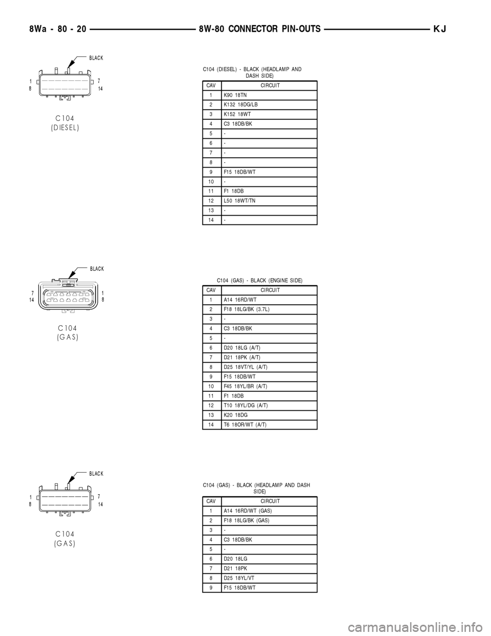
C104 (DIESEL) - BLACK (HEADLAMP AND
DASH SIDE)
CAV CIRCUIT
1 K90 18TN
2 K132 18DG/LB
3 K152 18WT
4 C3 18DB/BK
5-
6-
7-
8-
9 F15 18DB/WT
10 -
11 F1 18DB
12 L50 18WT/TN
13 -
14 -
C104 (GAS) - BLACK (ENGINE SIDE)
CAV CIRCUIT
1 A14 16RD/WT
2 F18 18LG/BK (3.7L)
3-
4 C3 18DB/BK
5-
6 D20 18LG (A/T)
7 D21 18PK (A/T)
8 D25 18VT/YL (A/T)
9 F15 18DB/WT
10 F45 18YL/BR (A/T)
11 F1 18DB
12 T10 18YL/DG (A/T)
13 K20 18DG
14 T6 18OR/WT (A/T)
C104 (GAS) - BLACK (HEADLAMP AND DASH
SIDE)
CAV CIRCUIT
1 A14 16RD/WT (GAS)
2 F18 18LG/BK (GAS)
3-
4 C3 18DB/BK
5-
6 D20 18LG
7 D21 18PK
8 D25 18YL/VT
9 F15 18DB/WT
8Wa - 80 - 20 8W-80 CONNECTOR PIN-OUTSKJ
Page 1081 of 1803

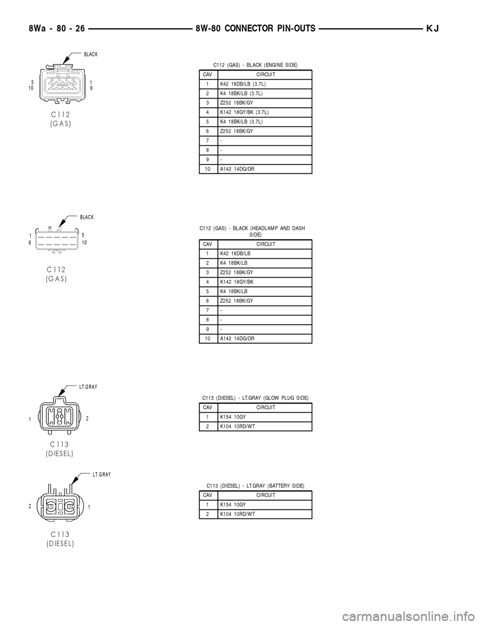
C112 (GAS) - BLACK (ENGINE SIDE)
CAV CIRCUIT
1 K42 18DB/LB (3.7L)
2 K4 18BK/LB (3.7L)
3 Z252 18BK/GY
4 K142 18GY/BK (3.7L)
5 K4 18BK/LB (3.7L)
6 Z252 18BK/GY
7-
8-
9-
10 A142 14DG/OR
C112 (GAS) - BLACK (HEADLAMP AND DASH
SIDE)
CAV CIRCUIT
1 K42 18DB/LB
2 K4 18BK/LB
3 Z252 18BK/GY
4 K142 18GY/BK
5 K4 18BK/LB
6 Z252 18BK/GY
7-
8-
9-
10 A142 14DG/OR
C113 (DIESEL) - LT.GRAY (GLOW PLUG SIDE)
CAV CIRCUIT
1 K154 10GY
2 K104 10RD/WT
C113 (DIESEL) - LT.GRAY (BATTERY SIDE)
CAV CIRCUIT
1 K154 10GY
2 K104 10RD/WT
8Wa - 80 - 26 8W-80 CONNECTOR PIN-OUTSKJ
Page 1137 of 1803

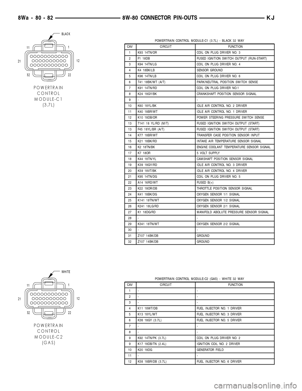
POWERTRAIN CONTROL MODULE-C1 (3.7L) - BLACK 32 WAY
CAV CIRCUIT FUNCTION
1 K93 14TN/OR COIL ON PLUG DRIVER NO. 3
2 F1 18DB FUSED IGNITION SWITCH OUTPUT (RUN-START)
3 K94 14TN/LG COIL ON PLUG DRIVER NO. 4
4 K4 18BK/LB SENSOR GROUND
5 K96 14TN/LB COIL ON PLUG DRIVER NO. 6
6 T41 18BK/WT (A/T) PARK/NEUTRAL POSITION SWITCH SENSE
7 K91 14TN/RD COIL ON PLUG DRIVER NO.1
8 K24 18GY/BK CRANKSHAFT POSITION SENSOR SIGNAL
9- -
10 K60 18YL/BK IDLE AIR CONTROL NO. 2 DRIVER
11 K40 18BR/WT IDLE AIR CONTROL NO. 1 DRIVER
12 K10 18DB/OR POWER STEERING PRESSURE SWITCH SENSE
13 T141 18 YL/RD (M/T) FUSED IGNITION SWITCH OUTPUT (START)
13 F45 18YL/BR (A/T) FUSED IGNITION SWITCH OUTPUT (START)
14 K77 18BR/WT TRANSFER CASE POSITION SENSOR INPUT
15 K21 18BK/RD INTAKE AIR TEMPERATURE SENSOR SIGNAL
16 K2 18TN/BK ENGINE COOLANT TEMPERATURE SENSOR SIGNAL
17 K7 18OR 5 VOLT SUPPLY
18 K44 18TN/YL CAMSHAFT POSITION SENSOR SIGNAL
19 K39 18GY/RD IDLE AIR CONTROL NO. 3 DRIVER
20 K59 18VT/BK IDLE AIR CONTROL NO. 4 DRIVER
21 K95 14TN/DG COIL ON PLUG DRIVER NO. 5
22 A14 16RD/WT FUSED B(+)
23 K22 18OR/DB THROTTLE POSITION SENSOR SIGNAL
24 K41 18BK/DG OXYGEN SENSOR 1/1 SIGNAL
25 K141 18TN/WT OXYGEN SENSOR 1/2 SIGNAL
26 K241 18LG/RD OXYGEN SENSOR 2/1 SIGNAL
27 K1 18DG/RD MANIFOLD ABOLUTE PRESSURE SENSOR SIGNAL
28 - -
29 K341 18TN/WT OXYGEN SENSOR 2/2 SIGNAL
30 - -
31 Z107 14BK/DB GROUND
32 Z107 14BK/DB GROUND
POWERTRAIN CONTROL MODULE-C2 (GAS) - WHITE 32 WAY
CAV CIRCUIT FUNCTION
1- -
2- -
3- -
4 K11 18WT/DB FUEL INJECTOR NO. 1 DRIVER
5 K13 18YL/WT FUEL INJECTOR NO. 3 DRIVER
6 K38 18GY (3.7L) FUEL INJECTOR NO. 5 DRIVER
7- -
8- -
9 K92 14TN/PK (3.7L) COIL ON PLUG DRIVER NO. 2
9 K17 18DB/TN (2.4L) IGNITION COIL NO. 2 DRIVER
10 K20 18DG GENERATOR FIELD
11 - -
12 K58 18BR/DB (3.7L) FUEL INJECTOR NO. 6 DRIVER
8Wa - 80 - 82 8W-80 CONNECTOR PIN-OUTSKJ
Page 1138 of 1803

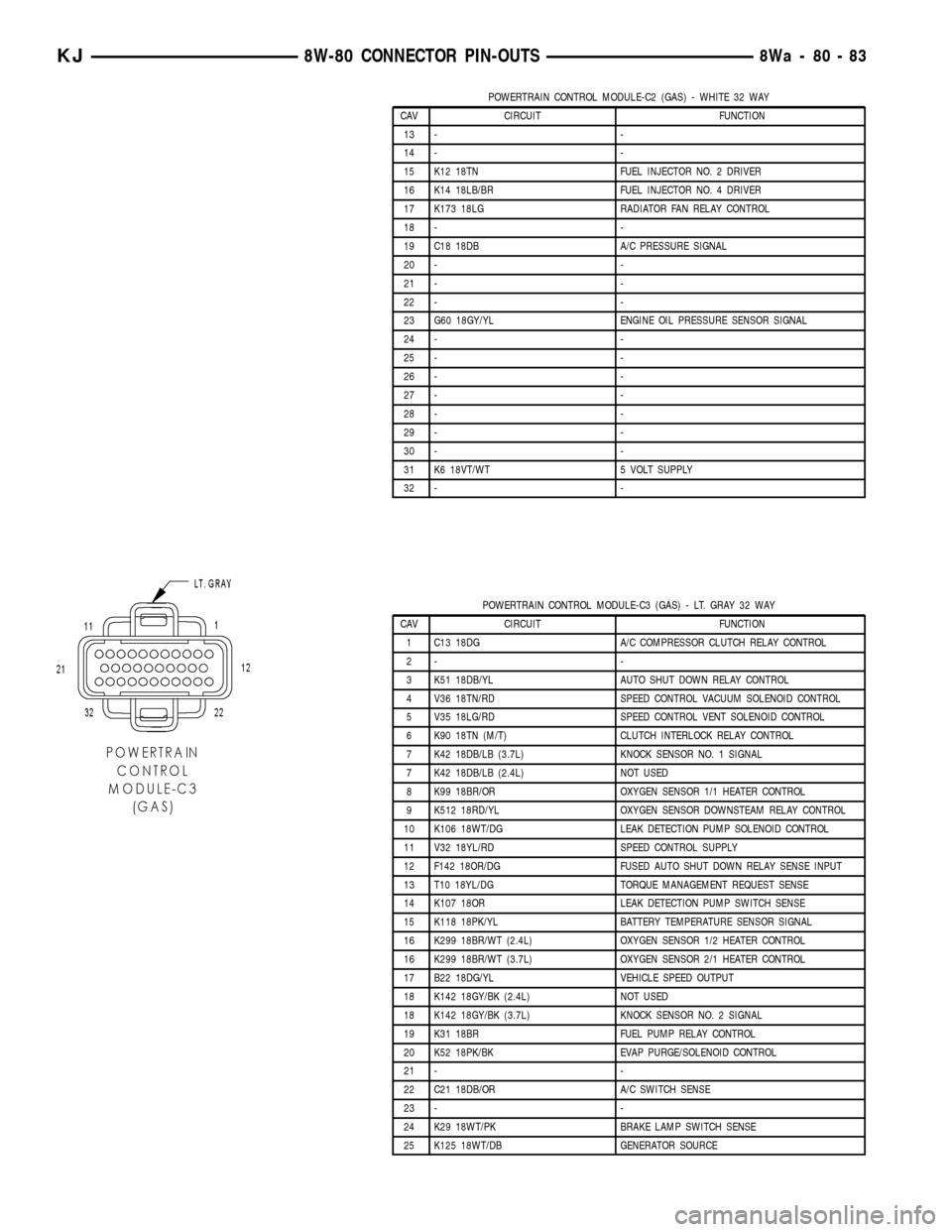
POWERTRAIN CONTROL MODULE-C2 (GAS) - WHITE 32 WAY
CAV CIRCUIT FUNCTION
13 - -
14 - -
15 K12 18TN FUEL INJECTOR NO. 2 DRIVER
16 K14 18LB/BR FUEL INJECTOR NO. 4 DRIVER
17 K173 18LG RADIATOR FAN RELAY CONTROL
18 - -
19 C18 18DB A/C PRESSURE SIGNAL
20 - -
21 - -
22 - -
23 G60 18GY/YL ENGINE OIL PRESSURE SENSOR SIGNAL
24 - -
25 - -
26 - -
27 - -
28 - -
29 - -
30 - -
31 K6 18VT/WT 5 VOLT SUPPLY
32 - -
POWERTRAIN CONTROL MODULE-C3 (GAS) - LT. GRAY 32 WAY
CAV CIRCUIT FUNCTION
1 C13 18DG A/C COMPRESSOR CLUTCH RELAY CONTROL
2- -
3 K51 18DB/YL AUTO SHUT DOWN RELAY CONTROL
4 V36 18TN/RD SPEED CONTROL VACUUM SOLENOID CONTROL
5 V35 18LG/RD SPEED CONTROL VENT SOLENOID CONTROL
6 K90 18TN (M/T) CLUTCH INTERLOCK RELAY CONTROL
7 K42 18DB/LB (3.7L) KNOCK SENSOR NO. 1 SIGNAL
7 K42 18DB/LB (2.4L) NOT USED
8 K99 18BR/OR OXYGEN SENSOR 1/1 HEATER CONTROL
9 K512 18RD/YL OXYGEN SENSOR DOWNSTEAM RELAY CONTROL
10 K106 18WT/DG LEAK DETECTION PUMP SOLENOID CONTROL
11 V32 18YL/RD SPEED CONTROL SUPPLY
12 F142 18OR/DG FUSED AUTO SHUT DOWN RELAY SENSE INPUT
13 T10 18YL/DG TORQUE MANAGEMENT REQUEST SENSE
14 K107 18OR LEAK DETECTION PUMP SWITCH SENSE
15 K118 18PK/YL BATTERY TEMPERATURE SENSOR SIGNAL
16 K299 18BR/WT (2.4L) OXYGEN SENSOR 1/2 HEATER CONTROL
16 K299 18BR/WT (3.7L) OXYGEN SENSOR 2/1 HEATER CONTROL
17 B22 18DG/YL VEHICLE SPEED OUTPUT
18 K142 18GY/BK (2.4L) NOT USED
18 K142 18GY/BK (3.7L) KNOCK SENSOR NO. 2 SIGNAL
19 K31 18BR FUEL PUMP RELAY CONTROL
20 K52 18PK/BK EVAP PURGE/SOLENOID CONTROL
21 - -
22 C21 18DB/OR A/C SWITCH SENSE
23 - -
24 K29 18WT/PK BRAKE LAMP SWITCH SENSE
25 K125 18WT/DB GENERATOR SOURCE
KJ8W-80 CONNECTOR PIN-OUTS8Wa-80-83