2002 JEEP LIBERTY radiator cap
[x] Cancel search: radiator capPage 862 of 1803

8W-30 FUEL/IGNITION SYSTEM
Component Page
A/C Compressor Clutch.............. 8Wa-30-34
A/C Compressor Clutch Relay..... 8Wa-30-34, 2, 3
A/C High Pressure Switch............ 8Wa-30-29
A/C Low Pressure Switch.......... 8Wa-30-8, 29
A/C Pressure Transducer....... 8Wa-30-11, 23, 12
Accelerator Pedal Position Sensor...... 8Wa-30-27
Auto Shut Down Relay . . 8Wa-30-13, 14, 15, 24, 28,
31, 16, 17, 2
Battery Temperature Sensor........ 8Wa-30-30, 7
Blower Motor Relay................. 8Wa-30-31
Body Control Module.............. 8Wa-30-8, 33
Boost Pressure Sensor............ 8Wa-30-26, 28
Brake Lamp Switch............ 8Wa-30-8, 32, 33
Cabin Heater...................... 8Wa-30-34
Cabin Heater Relay................. 8Wa-30-34
Camshaft Position Sensor....... 8Wa-30-10, 9, 28
Capacitor...................... 8Wa-30-19, 17
Clockspring..................... 8Wa-30-33, 7
Clutch Switch Override Relay.... 8Wa-30-13, 8, 32
Coil On Plug No. 1................. 8Wa-30-19
Coil On Plug No. 2................. 8Wa-30-20
Coil On Plug No. 3................. 8Wa-30-19
Coil On Plug No. 4................. 8Wa-30-20
Coil On Plug No. 5................. 8Wa-30-19
Coil On Plug No. 6................. 8Wa-30-20
Coil Rail......................... 8Wa-30-17
Controller Antilock Brake............ 8Wa-30-33
Crankshaft Position Sensor...... 8Wa-30-10, 9, 27
Data Link Connector.............. 8Wa-30-25, 6
Diagnostic Junction Port........... 8Wa-30-25, 6
EGR Solenoid..................... 8Wa-30-30
Engine Control Module . . 8Wa-30-24, 25, 26, 27, 28,
29, 30, 31, 32, 33, 34, 35, 36
Engine Coolant Temperature Sensor . 8Wa-30-11, 28,
12
Engine Oil Pressure Sensor..... 8Wa-30-11, 28, 12
Evap/Purge Solenoid................. 8Wa-30-2
Fuel Heater....................... 8Wa-30-31
Fuel Heater Relay.................. 8Wa-30-31
Fuel Injector No. 1............... 8Wa-30-18, 36
Fuel Injector No. 2............... 8Wa-30-18, 36
Fuel Injector No. 3............... 8Wa-30-18, 36
Fuel Injector No. 4............... 8Wa-30-18, 36
Fuel Injector No. 5................. 8Wa-30-18
Fuel Injector No. 6................. 8Wa-30-18
Fuel Pressure Sensor............... 8Wa-30-36
Fuel Pressure Solenoid.............. 8Wa-30-31
Fuel Pump Module............. 8Wa-30-30, 4, 5
Fuel Pump Relay.............. 8Wa-30-4, 2, 3, 5
Fuse 2........................... 8Wa-30-23
Fuse 6................... 8Wa-30-24, 28, 31, 2Component Page
Fuse 10.......................... 8Wa-30-35
Fuse 11.......................... 8Wa-30-35
Fuse 12....................... 8Wa-30-31, 33
Fuse 15...................... 8Wa-30-25, 2, 3
Fuse 16...... 8Wa-30-13, 14, 15, 24, 30, 34, 35, 16
Fuse 21.......................... 8Wa-30-34
Fuse 24...................... 8Wa-30-31, 2, 3
Fuse 26.................. 8Wa-30-18, 24, 17, 2
Fuse 28.......................... 8Wa-30-13
G100.................... 8Wa-30-19, 27, 17, 3
G101............................ 8Wa-30-23
G103................. 8Wa-30-15, 23, 31, 34, 16
G104............................ 8Wa-30-27
G111 ............................ 8Wa-30-31
G112 .......................... 8Wa-30-8, 23
G320........................... 8Wa-30-4, 5
Generator.................. 8Wa-30-24, 4, 3, 5
Glow Plug Assembly................ 8Wa-30-35
Glow Plug Relay No. 1.............. 8Wa-30-35
Glow Plug Relay No. 2.............. 8Wa-30-35
Idle Air Control Motor............ 8Wa-30-21, 22
Ignition Switch.................... 8Wa-30-32
Intake Air Temperature Sensor..... 8Wa-30-11, 12
Junction Block........... 8Wa-30-25, 31, 33, 2, 3
Knock Sensor...................... 8Wa-30-8
Leak Detection Pump.............. 8Wa-30-4, 5
Left Speed Control Switch.......... 8Wa-30-33, 7
Manifold Absolute Pressure Sensor . . 8Wa-30-11, 12
Oxygen Sensor 1/1 Upstream...... 8Wa-30-14, 15
Oxygen Sensor 1/2 Downstream . 8Wa-30-13, 14, 15
Oxygen Sensor 2/1 Upstream......... 8Wa-30-16
Oxygen Sensor 2/2 Downstream.... 8Wa-30-13, 16
Oxygen Sensor Downstream Relay . . 8Wa-30-13, 15,
16
Power Distribution Center . . 8Wa-30-13, 14, 15, 23,
24, 28, 30, 31, 34, 35, 16, 17, 2, 3
Power Steering Pressure Switch....... 8Wa-30-23
Powertrain Control Module . . . 8Wa-30-10, 13, 20, 8,
11, 14, 15, 18, 19, 21, 9, 23, 4, 12, 16, 17, 2, 22, 3,
6, 7, 5
Radiator Fan Motor................. 8Wa-30-23
Radiator Fan Relay................. 8Wa-30-23
Right Speed Control Switch......... 8Wa-30-33, 7
Shifter Assembly................. 8Wa-30-8, 32
Speed Control Servo................. 8Wa-30-8
Starter Motor Relay................ 8Wa-30-13
Throttle Position Sensor.......... 8Wa-30-21, 22
Transfer Case Position Sensor.... 8Wa-30-9, 23, 32
Transmission Control Module . . 8Wa-30-10, 8, 22, 6
Transmission Solenoid/Trs Assembly.... 8Wa-30-10
Water In Fuel Sensor............... 8Wa-30-29
KJ8W-30 FUEL/IGNITION SYSTEM8Wa-30-1
Page 1223 of 1803
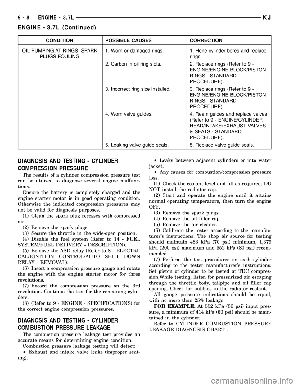
CONDITION POSSIBLE CAUSES CORRECTION
OIL PUMPING AT RINGS; SPARK
PLUGS FOULING1. Worn or damaged rings. 1. Hone cylinder bores and replace
rings.
2. Carbon in oil ring slots. 2. Replace rings (Refer to 9 -
ENGINE/ENGINE BLOCK/PISTON
RINGS - STANDARD
PROCEDURE).
3. Incorrect ring size installed. 3. Replace rings (Refer to 9 -
ENGINE/ENGINE BLOCK/PISTON
RINGS - STANDARD
PROCEDURE).
4. Worn valve guides. 4. Ream guides and replace valves
(Refer to 9 - ENGINE/CYLINDER
HEAD/INTAKE/EXHAUST VALVES
& SEATS - STANDARD
PROCEDURE).
5. Leaking valve guide seals. 5. Replace valve guide seals.
DIAGNOSIS AND TESTING - CYLINDER
COMPRESSION PRESSURE
The results of a cylinder compression pressure test
can be utilized to diagnose several engine malfunc-
tions.
Ensure the battery is completely charged and the
engine starter motor is in good operating condition.
Otherwise the indicated compression pressures may
not be valid for diagnosis purposes.
(1) Clean the spark plug recesses with compressed
air.
(2) Remove the spark plugs.
(3) Secure the throttle in the wide-open position.
(4) Disable the fuel system (Refer to 14 - FUEL
SYSTEM/FUEL DELIVERY - DESCRIPTION).
(5) Remove the ASD relay (Refer to 8 - ELECTRI-
CAL/IGNITION CONTROL/AUTO SHUT DOWN
RELAY - REMOVAL).
(6) Insert a compression pressure gauge and rotate
the engine with the engine starter motor for three
revolutions.
(7) Record the compression pressure on the 3rd
revolution. Continue the test for the remaining cylin-
ders.
(8) (Refer to 9 - ENGINE - SPECIFICATIONS) for
the correct engine compression pressures.
DIAGNOSIS AND TESTING - CYLINDER
COMBUSTION PRESSURE LEAKAGE
The combustion pressure leakage test provides an
accurate means for determining engine condition.
Combustion pressure leakage testing will detect:
²Exhaust and intake valve leaks (improper seat-
ing).²Leaks between adjacent cylinders or into water
jacket.
²Any causes for combustion/compression pressure
loss.
(1) Check the coolant level and fill as required. DO
NOT install the radiator cap.
(2) Start and operate the engine until it attains
normal operating temperature, then turn the engine
OFF.
(3) Remove the spark plugs.
(4) Remove the oil filler cap.
(5) Remove the air cleaner.
(6) Calibrate the tester according to the manufac-
turer's instructions. The shop air source for testing
should maintain 483 kPa (70 psi) minimum, 1,379
kPa (200 psi) maximum and 552 kPa (80 psi) recom-
mended.
(7) Perform the test procedures on each cylinder
according to the tester manufacturer's instructions.
Set piston of cylinder to be tested at TDC compres-
sion,While testing, listen for pressurized air escaping
through the throttle body, tailpipe and oil filler cap
opening. Check for bubbles in the radiator coolant.
All gauge pressure indications should be equal,
with no more than 25% leakage.
FOR EXAMPLE:At 552 kPa (80 psi) input pres-
sure, a minimum of 414 kPa (60 psi) should be main-
tained in the cylinder.
Refer to CYLINDER COMBUSTION PRESSURE
LEAKAGE DIAGNOSIS CHART .
9 - 8 ENGINE - 3.7LKJ
ENGINE - 3.7L (Continued)
Page 1224 of 1803
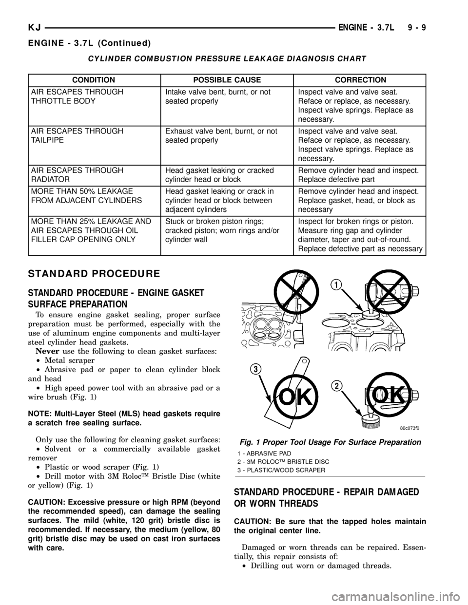
CYLINDER COMBUSTION PRESSURE LEAKAGE DIAGNOSIS CHART
CONDITION POSSIBLE CAUSE CORRECTION
AIR ESCAPES THROUGH
THROTTLE BODYIntake valve bent, burnt, or not
seated properlyInspect valve and valve seat.
Reface or replace, as necessary.
Inspect valve springs. Replace as
necessary.
AIR ESCAPES THROUGH
TAILPIPEExhaust valve bent, burnt, or not
seated properlyInspect valve and valve seat.
Reface or replace, as necessary.
Inspect valve springs. Replace as
necessary.
AIR ESCAPES THROUGH
RADIATORHead gasket leaking or cracked
cylinder head or blockRemove cylinder head and inspect.
Replace defective part
MORE THAN 50% LEAKAGE
FROM ADJACENT CYLINDERSHead gasket leaking or crack in
cylinder head or block between
adjacent cylindersRemove cylinder head and inspect.
Replace gasket, head, or block as
necessary
MORE THAN 25% LEAKAGE AND
AIR ESCAPES THROUGH OIL
FILLER CAP OPENING ONLYStuck or broken piston rings;
cracked piston; worn rings and/or
cylinder wallInspect for broken rings or piston.
Measure ring gap and cylinder
diameter, taper and out-of-round.
Replace defective part as necessary
STANDARD PROCEDURE
STANDARD PROCEDURE - ENGINE GASKET
SURFACE PREPARATION
To ensure engine gasket sealing, proper surface
preparation must be performed, especially with the
use of aluminum engine components and multi-layer
steel cylinder head gaskets.
Neveruse the following to clean gasket surfaces:
²Metal scraper
²Abrasive pad or paper to clean cylinder block
and head
²High speed power tool with an abrasive pad or a
wire brush (Fig. 1)
NOTE: Multi-Layer Steel (MLS) head gaskets require
a scratch free sealing surface.
Only use the following for cleaning gasket surfaces:
²Solvent or a commercially available gasket
remover
²Plastic or wood scraper (Fig. 1)
²Drill motor with 3M RolocŸ Bristle Disc (white
or yellow) (Fig. 1)
CAUTION: Excessive pressure or high RPM (beyond
the recommended speed), can damage the sealing
surfaces. The mild (white, 120 grit) bristle disc is
recommended. If necessary, the medium (yellow, 80
grit) bristle disc may be used on cast iron surfaces
with care.
STANDARD PROCEDURE - REPAIR DAMAGED
OR WORN THREADS
CAUTION: Be sure that the tapped holes maintain
the original center line.
Damaged or worn threads can be repaired. Essen-
tially, this repair consists of:
²Drilling out worn or damaged threads.
Fig. 1 Proper Tool Usage For Surface Preparation
1 - ABRASIVE PAD
2 - 3M ROLOCŸ BRISTLE DISC
3 - PLASTIC/WOOD SCRAPER
KJENGINE - 3.7L 9 - 9
ENGINE - 3.7L (Continued)
Page 1227 of 1803
(35) Install the mechanical cooling fan.
(36) Install the fan shroud with the electric fan
assembly.
(37) Install the radiator core support bracket.
(38) Install the air cleaner assembly.
(39) Refill the engine cooling system.
(40) Install the hood.
(41) Check and fill engine oil.
(42) Connect the battery negative cable.
(43) Start the engine and check for leaks.
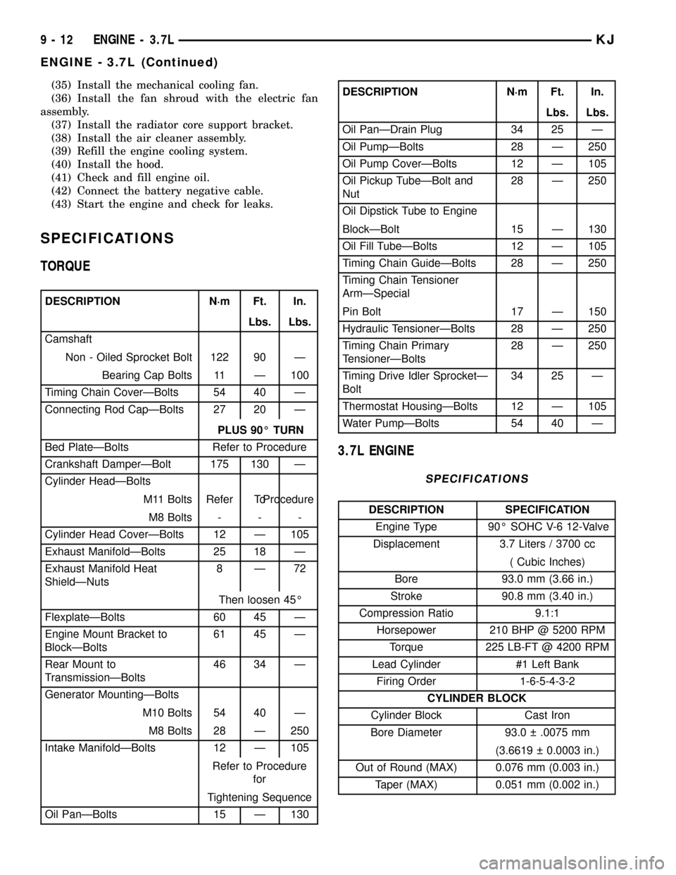
SPECIFICATIONS
TORQUE
DESCRIPTION N´m Ft. In.
Lbs. Lbs.
Camshaft
Non - Oiled Sprocket Bolt 122 90 Ð
Bearing Cap Bolts 11 Ð 100
Timing Chain CoverÐBolts 54 40 Ð
Connecting Rod CapÐBolts 27 20 Ð
PLUS 90É TURN
Bed PlateÐBolts Refer to Procedure
Crankshaft DamperÐBolt 175 130 Ð
Cylinder HeadÐBolts
M11 Bolts Refer ToProcedure
M8 Bolts - - -
Cylinder Head CoverÐBolts 12 Ð 105
Exhaust ManifoldÐBolts 25 18 Ð
Exhaust Manifold Heat
ShieldÐNuts8Ð72
Then loosen 45É
FlexplateÐBolts 60 45 Ð
Engine Mount Bracket to
BlockÐBolts61 45 Ð
Rear Mount to
TransmissionÐBolts46 34 Ð
Generator MountingÐBolts
M10 Bolts 54 40 Ð
M8 Bolts 28 Ð 250
Intake ManifoldÐBolts 12 Ð 105
Refer to Procedure
for
Tightening Sequence
Oil PanÐBolts 15 Ð 130
DESCRIPTION N´m Ft. In.
Lbs. Lbs.
Oil PanÐDrain Plug 34 25 Ð
Oil PumpÐBolts 28 Ð 250
Oil Pump CoverÐBolts 12 Ð 105
Oil Pickup TubeÐBolt and
Nut28 Ð 250
Oil Dipstick Tube to Engine
BlockÐBolt 15 Ð 130
Oil Fill TubeÐBolts 12 Ð 105
Timing Chain GuideÐBolts 28 Ð 250
Timing Chain Tensioner
ArmÐSpecial
Pin Bolt 17 Ð 150
Hydraulic TensionerÐBolts 28 Ð 250
Timing Chain Primary
TensionerÐBolts28 Ð 250
Timing Drive Idler SprocketÐ
Bolt34 25 Ð
Thermostat HousingÐBolts 12 Ð 105
Water PumpÐBolts 54 40 Ð
3.7L ENGINE
SPECIFICATIONS
DESCRIPTION SPECIFICATION
Engine Type 90É SOHC V-6 12-Valve
Displacement 3.7 Liters / 3700 cc
( Cubic Inches)
Bore 93.0 mm (3.66 in.)
Stroke 90.8 mm (3.40 in.)
Compression Ratio 9.1:1
Horsepower 210 BHP @ 5200 RPM
Torque 225 LB-FT @ 4200 RPM
Lead Cylinder #1 Left Bank
Firing Order 1-6-5-4-3-2
CYLINDER BLOCK
Cylinder Block Cast Iron
Bore Diameter 93.0 .0075 mm
(3.6619 0.0003 in.)
Out of Round (MAX) 0.076 mm (0.003 in.)
Taper (MAX) 0.051 mm (0.002 in.)
9 - 12 ENGINE - 3.7LKJ
ENGINE - 3.7L (Continued)
Page 1317 of 1803

Possible indications of the cylinder head gasket
leaking between a cylinder and an adjacent water
jacket are:
²Engine overheating
²Loss of coolant
²Excessive steam (white smoke) emitting from
exhaust
²Coolant foaming
CYLINDER-TO-CYLINDER LEAKAGE TEST
To determine if an engine cylinder head gasket is
leaking between adjacent cylinders, follow the proce-
dures in Cylinder Compression Pressure Test (Refer
to 9 - ENGINE - DIAGNOSIS AND TESTING). An
engine cylinder head gasket leaking between adja-
cent cylinders will result in approximately a 50±70%
reduction in compression pressure.
CYLINDER-TO-WATER JACKET LEAKAGE TEST
WARNING: USE EXTREME CAUTION WHEN THE
ENGINE IS OPERATING WITH COOLANT PRES-
SURE CAP REMOVED.
VISUAL TEST METHOD
With the engine cool, remove the coolant pressure
cap. Start the engine and allow it to warm up until
thermostat opens.
If a large combustion/compression pressure leak
exists, bubbles will be visible in the coolant.
COOLING SYSTEM TESTER METHOD
WARNING: WITH COOLING SYSTEM TESTER IN
PLACE, PRESSURE WILL BUILD UP FAST. EXCES-
SIVE PRESSURE BUILT UP, BY CONTINUOUS
ENGINE OPERATION, MUST BE RELEASED TO A
SAFE PRESSURE POINT. NEVER PERMIT PRES-
SURE TO EXCEED 138 kPa (20 psi).
Install Cooling System Tester 7700 or equivalent to
pressure cap neck. Start the engine and observe the
tester's pressure gauge. If gauge pulsates with every
power stroke of a cylinder a combustion pressure
leak is evident.
CHEMICAL TEST METHOD
Combustion leaks into the cooling system can also
be checked by using Bloc-Chek Kit C-3685-A or
equivalent. Perform test following the procedures
supplied with the tool kit.
REMOVAL - CYLINDER HEAD
(1) Perform fuel system pressure release procedure
before attempting any repairs.(Refer to 14 -FUEL SYSTEM/FUEL DELIVERY - SPECIFICA-
TIONS)
(2) Disconnect battery negative cable.
(3) Drain cooling system. (Refer to 7 - COOLING -
STANDARD PROCEDURE)
(4) Remove air filter housing and inlet tube.
(5) Remove intake manifold.
(6) Remove heater tube support bracket from cyl-
inder head.
(7) Disconnect radiator upper and heater supply
hoses from water outlet connections.
(8) Remove accessory drive belts. (Refer to 7 -
COOLING/ACCESSORY DRIVE/DRIVE BELTS -
REMOVAL)
(9) Raise vehicle and remove exhaust pipe from
manifold.
(10) Remove power steering pump and set aside.
Do not disconnect lines.
(11) Remove accessory drive bracket
(12) Remove ignition coil and wires from engine.
(13) Disconnect cam sensor and fuel injector wir-
ing connectors.
(14) Remove timing belt and camshaft sprockets.
(Refer to 9 - ENGINE/VALVE TIMING/TIMING
BELT/CHAIN AND SPROCKETS - REMOVAL)
(15) Remove timing belt idler pulley and rear tim-
ing belt cover. (Refer to 9 - ENGINE/VALVE TIM-
ING/TIMING BELT / CHAIN COVER(S) -
REMOVAL)
(16) Remove cylinder head cover. (Refer to 9 -
ENGINE/CYLINDER HEAD/CYLINDER HEAD
COVER(S) - REMOVAL)
(17) Remove camshafts (Refer to 9 - ENGINE/
CYLINDER HEAD/CAMSHAFT(S) - REMOVAL).
NOTE: Identify rocker arm position to ensure cor-
rect re-installation in original position, if reused.
(18) Remove rocker arms. (Refer to 9 - ENGINE/
CYLINDER HEAD/ROCKER ARMS - REMOVAL).
(19) Remove cylinder head bolts in REVERSE
sequence of tightening.
(20) Remove cylinder head from engine block.
(21) Inspect and clean cylinder head. (Refer to 9 -
ENGINE/CYLINDER HEAD - INSPECTION) (Refer
to 9 - ENGINE/CYLINDER HEAD - CLEANING)
CLEANING
To ensure engine gasket sealing, proper surface
preparation must be performed, especially with the
use of aluminum engine components and multi-layer
steel cylinder head gaskets.
NOTE: Multi-Layer Steel (MLS) head gaskets require
a scratch free sealing surface.
9s - 20 ENGINEKJ
CYLINDER HEAD (Continued)
Page 1448 of 1803
NOTE: Power steering pumps have different pres-
sure rates and are not interchangeable with other
pumps.
STANDARD PROCEDURE - POWER STEERING
PUMP - INITIAL OPERATION
WARNING: THE FLUID LEVEL SHOULD BE
CHECKED WITH ENGINE OFF TO PREVENT INJURY
FROM MOVING COMPONENTS.
CAUTION: Use MOPAR Power Steering Fluid or
equivalent. Do not use automatic transmission fluid
and do not overfill.
Wipe filler cap clean, then check the fluid level.
The dipstick should indicateCOLDwhen the fluid is
at normal ambient temperature.
(1) Fill the pump fluid reservoir to the proper level
and let the fluid settle for at least two minutes.
(2) Raise the front wheels off the ground.
(3) Slowly turn the steering wheel right and left,
lightly contacting the wheel stops at least 20 times.
(4) Check the fluid level add if necessary.
(5) Lower the vehicle, start the engine and turn
the steering wheel slowly from lock to lock.
(6) Stop the engine and check the fluid level and
refill as required.
CAUTION: Do not run a vehicle with foamy fluid for
an extended period. This may cause pump damage.
(7) If the fluid is extremely foamy or milky look-
ing, allow the vehicle to stand a few minutes and
repeat the procedure.
(8) Add fluid if necessary. Repeat the above proce-
dure until the fluid level remains constant after run-
ning the engine.
REMOVAL
REMOVAL - 3.7L
(1) Siphon out as much power steering fluid as
possible.
(2) Remove the radiator cross member (Refer to 23
- BODY/EXTERIOR/RADIATOR CROSSMEMBER -
REMOVAL).
(3) Remove the engine cooling fan (Refer to 7 -
COOLING/ENGINE/RADIATOR FAN - REMOVAL).
(4) Remove the fan shroud
(5) Remove the serpentine drive belt (Refer to 7 -
COOLING/ACCESSORY DRIVE/DRIVE BELTS -
REMOVAL).
(6) Remove the power steering high pressure hose
at the pump.
(7) Remove the return hose at the pump.
(8) Remove the three bolts securing the pump to
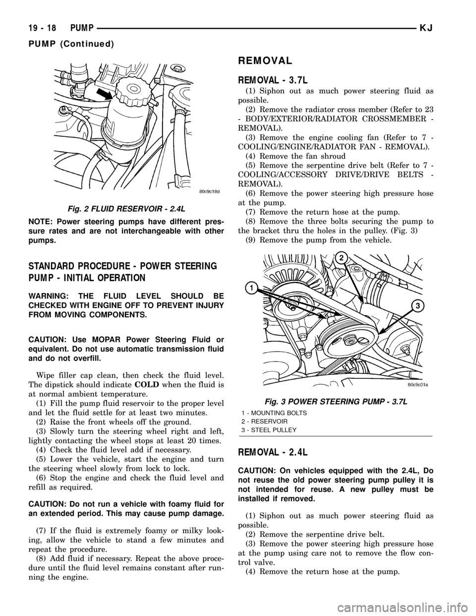
the bracket thru the holes in the pulley. (Fig. 3)
(9) Remove the pump from the vehicle.
REMOVAL - 2.4L
CAUTION: On vehicles equipped with the 2.4L, Do
not reuse the old power steering pump pulley it is
not intended for reuse. A new pulley must be
installed if removed.
(1) Siphon out as much power steering fluid as
possible.
(2) Remove the serpentine drive belt.
(3) Remove the power steering high pressure hose
at the pump using care not to remove the flow con-
trol valve.
(4) Remove the return hose at the pump.
Fig. 2 FLUID RESERVOIR - 2.4L
Fig. 3 POWER STEERING PUMP - 3.7L
1 - MOUNTING BOLTS
2 - RESERVOIR
3 - STEEL PULLEY
19 - 18 PUMPKJ
PUMP (Continued)
Page 1653 of 1803
HEATING & AIR CONDITIONING
TABLE OF CONTENTS
page page
HEATING & AIR CONDITIONING
DESCRIPTION
DESCRIPTION - HEATER AND AIR
CONDITIONER........................1
DESCRIPTION - COOLING SYSTEM
REQUIREMENTS.......................1
DESCRIPTION - REFRIGERANT SYSTEM
SERVICE PORT........................2
OPERATION
OPERATION - HEATER AND AIR
CONDITIONER........................2
OPERATION - REFRIGERANT SYSTEM
SERVICE PORT........................2
DIAGNOSIS AND TESTING
DIAGNOSIS AND TESTING - A/C
PERFORMANCE.......................2DIAGNOSIS AND TESTING - HEATER
PERFORMANCE.......................6
DIAGNOSIS AND TESTING - VACUUM
SYSTEM.............................6
STANDARD PROCEDURE - DIODE
REPLACEMENT.......................9
SPECIFICATIONS
A/C APPLICATION TABLE................9
SPECIFICATIONS.....................10
CONTROLS.............................11
DISTRIBUTION..........................29
PLUMBING.............................38
HEATING & AIR
CONDITIONING
DESCRIPTION
DESCRIPTION - HEATER AND AIR
CONDITIONER
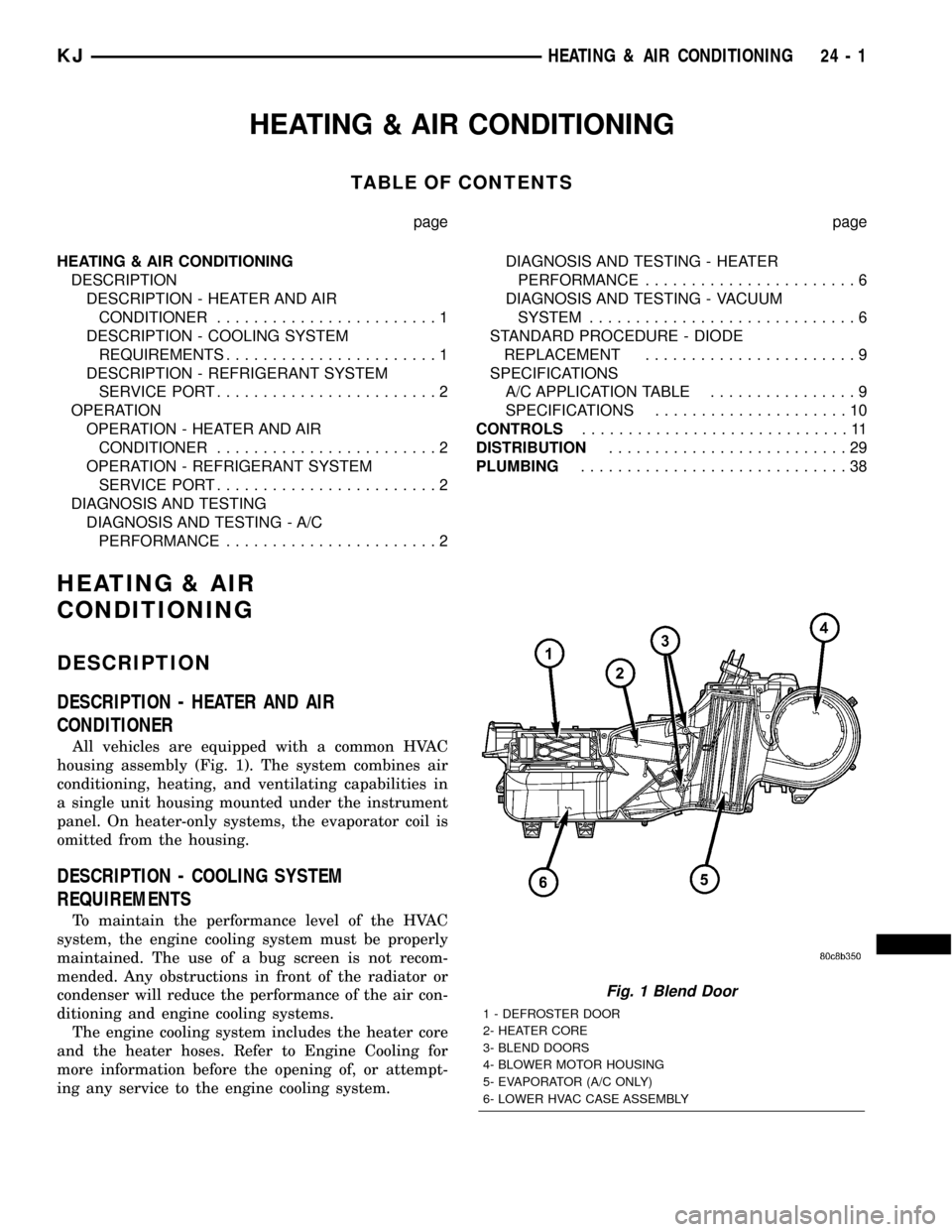
All vehicles are equipped with a common HVAC
housing assembly (Fig. 1). The system combines air
conditioning, heating, and ventilating capabilities in
a single unit housing mounted under the instrument
panel. On heater-only systems, the evaporator coil is
omitted from the housing.
DESCRIPTION - COOLING SYSTEM
REQUIREMENTS
To maintain the performance level of the HVAC
system, the engine cooling system must be properly
maintained. The use of a bug screen is not recom-
mended. Any obstructions in front of the radiator or
condenser will reduce the performance of the air con-
ditioning and engine cooling systems.
The engine cooling system includes the heater core
and the heater hoses. Refer to Engine Cooling for
more information before the opening of, or attempt-
ing any service to the engine cooling system.
Fig. 1 Blend Door
1 - DEFROSTER DOOR
2- HEATER CORE
3- BLEND DOORS
4- BLOWER MOTOR HOUSING
5- EVAPORATOR (A/C ONLY)
6- LOWER HVAC CASE ASSEMBLY
KJHEATING & AIR CONDITIONING 24 - 1
Page 1743 of 1803

BRAKE CALIPERS - OPERATION, DISC.....5-14
BRAKE CALIPERS - REMOVAL, DISC......5-14
BRAKE COMPONENTS, SPECIFICATIONS....5-6
BRAKE DRUM - DIAGNOSIS AND
TESTING............................5-27
BRAKE DRUM MACHINING - STANDARD
PROCEDURES........................5-27
BRAKE FLUID CONTAMINATION -
DIAGNOSIS AND TESTING..............5-26
BRAKE FLUID, SPECIFICATIONS..........5-27
BRAKE HOSE - INSTALLATION, FRONT.....5-10
BRAKE HOSE - INSTALLATION, REAR......5-10
BRAKE HOSE - REMOVAL, REAR..........5-9
BRAKE INDICATOR - DESCRIPTION,
BRAKE/PARK........................8J-13
BRAKE INDICATOR - DIAGNOSIS AND
TESTING...........................8J-14
BRAKE INDICATOR - OPERATION,
BRAKE/PARK........................8J-13
BRAKE LAMP SWITCH - DESCRIPTION . . . 8L-16
BRAKE LAMP SWITCH - DIAGNOSIS
AND TESTING.......................8L-17
BRAKE LAMP SWITCH - INSTALLATION . . . 8L-18
BRAKE LAMP SWITCH - OPERATION.....8L-16
BRAKE LAMP SWITCH - REMOVAL......8L-17
BRAKE LINE AND HOSES - DIAGNOSIS
AND TESTING.........................5-8
BRAKE LINES - DESCRIPTION............5-8
BRAKE PADS - INSTALLATION, FRONT.....5-11
BRAKE PADS - REMOVAL, FRONT........5-11
BRAKE ROTOR - DIAGNOSIS AND
TESTING, DISC.......................5-18
BRAKE ROTOR - STANDARD
PROCEDURE, DISC....................5-19
BRAKE SHOES - INSTALLATION, DRUM....5-11
BRAKE SHOES - REMOVAL, DRUM.......5-11
BRAKE SYSTEM - DIAGNOSIS AND
TESTING, BASE........................5-3
BRAKE TRANSMISSION SHIFT
INTERLOCK SYSTEM - DESCRIPTION....21-124
BRAKE TRANSMISSION SHIFT
INTERLOCK SYSTEM - DIAGNOSIS
AND TESTING......................21-125
BRAKE TRANSMISSION SHIFT
INTERLOCK SYSTEM - OPERATION.....21-125
BRAKE/PARK BRAKE INDICATOR -
DESCRIPTION.......................8J-13
BRAKE/PARK BRAKE INDICATOR -
OPERATION.........................8J-13
BRAKES - ABS - DESCRIPTION...........5-32
BRAKES - ABS - OPERATION............5-32
BRAKES - ABS - SPECIFICATIONS........5-33
BRAKES - BASE - DESCRIPTION...........5-2
BRAKES - BASE - WARNING..............5-2
BRAKES, SPECIAL TOOLS - BASE.........5-7
BRAKING SYSTEM - DIAGNOSIS AND
TESTING, ANTILOCK...................5-33
BREAK-IN - STANDARD PROCEDURE,
A/C COMPRESSOR CLUTCH............24-12
BUCKLE - INSTALLATION, FRONT SEAT
BELT ..............................8O-26
BUCKLE - INSTALLATION, REAR SEAT
BELT ..............................8O-35
BUCKLE - REMOVAL, FRONT SEAT BELT . . 8O-25
BUCKLE - REMOVAL, REAR SEAT BELT . . . 8O-34
BUILT-IN INDICATOR TEST - STANDARD
PROCEDURE........................8F-10
BULB - INSTALLATION, ASH RECEIVER
LAMP..............................8L-71
BULB - INSTALLATION, CARGO LAMP....8L-73
BULB - INSTALLATION, CENTER HIGH
MOUNTED STOP LAMP................8L-19
BULB - INSTALLATION, COMPASS
MINI-TRIP ILLUMINATION..............8L-75
BULB - INSTALLATION, COURTESY
LAMP..............................8L-76
BULB - INSTALLATION, FRONT FOG
LAMP..............................8L-22
BULB - INSTALLATION, FRONT LAMP....8L-27
BULB - INSTALLATION, FRONT POSITION
LAMP..............................8L-28
BULB - INSTALLATION, HEADLAMP
......8L-32
BULB - INSTALLATION, HEATER-A/C
CONTROL ILLUMINATION
..............8L-78
BULB - INSTALLATION, LICENSE PLATE
LAMP
..............................8L-45
BULB - INSTALLATION, READING LAMP
. . . 8L-79
BULB - INSTALLATION, REAR LAMP
.....8L-59BULB - INSTALLATION, REPEATER LAMP . . 8L-60
BULB - INSTALLATION, TRANSMISSION
RANGE INDICATOR ILLUMINATION.......8L-83
BULB - INSTALLATION, VANITY LAMP....8L-84
BULB - REMOVAL, ASH RECEIVER LAMP . . 8L-71
BULB - REMOVAL, CARGO LAMP........8L-72
BULB - REMOVAL, CENTER HIGH
MOUNTED STOP LAMP................8L-18
BULB - REMOVAL, COMPASS MINI-TRIP
ILLUMINATION......................8L-74
BULB - REMOVAL, COURTESY LAMP.....8L-75
BULB - REMOVAL, FRONT FOG LAMP....8L-21
BULB - REMOVAL, FRONT LAMP........8L-26
BULB - REMOVAL, FRONT POSITION
LAMP..............................8L-28
BULB - REMOVAL, HEADLAMP..........8L-31
BULB - REMOVAL, HEATER-A/C
CONTROL ILLUMINATION..............8L-78
BULB - REMOVAL, LICENSE PLATE
LAMP..............................8L-44
BULB - REMOVAL, READING LAMP......8L-79
BULB - REMOVAL, REAR LAMP.........8L-58
BULB - REMOVAL, REPEATER LAMP.....8L-60
BULB - REMOVAL, TRANSMISSION
RANGE INDICATOR ILLUMINATION.......8L-82
BULB - REMOVAL, VANITY LAMP........8L-83
BUMPER - INSTALLATION, JOUNCE.......2-19
BUMPER - REMOVAL, JOUNCE...........2-19
BURNT FLUID - DIAGNOSIS AND
TESTING, CAUSES OF................21-125
BUSHING - NV3550 - INSTALLATION,
EXTENSION HOUSING.................21-74
BUSHING - NV3550 - REMOVAL,
EXTENSION HOUSING.................21-73
BUSHINGS - INSTALLATION, STABILIZER
BAR.................................2-9
BUSHINGS - REMOVAL, STABILIZER BAR . . . 2-9
BUSHINGS, AND BALL JOINT -
DESCRIPTION, UPPER SUSPENSION
ARM ...............................2-20
BUSHINGS, AND BALL JOINT -
OPERATION, UPPER SUSPENSION
ARM ...............................2-20
CABLE - ADJUSTMENTS, GEARSHIFT....21-130
CABLE - ADJUSTMENTS, PARK-
INTERLOCK........................21-154
CABLE - DESCRIPTION.................8P-3
CABLE - DESCRIPTION, ANTENNA BODY . . . 8A-4
CABLE - DIAGNOSIS AND TESTING,
ANTENNA BODY......................8A-5
CABLE - DIAGNOSIS AND TESTING,
GEARSHIFT........................21-128
CABLE - INSTALLATION, ANTENNA BODY . . 8A-6
CABLE - INSTALLATION, GEARSHIFT....21-129
CABLE - INSTALLATION, INSTRUMENT
PANEL ANTENNA......................8A-8
CABLE - INSTALLATION, LATCH RELEASE . 23-120
CABLE - INSTALLATION, PARK -
INTERLOCK........................21-153
CABLE - INSTALLATION, THROTTLE
CONTROL..........................14-46
CABLE - OPERATION...................8P-3
CABLE - OPERATION, ANTENNA BODY.....8A-5
CABLE - REMOVAL, ANTENNA BODY......8A-6
CABLE - REMOVAL, GEARSHIFT........21-128
CABLE - REMOVAL, INSTRUMENT PANEL
ANTENNA...........................8A-7
CABLE - REMOVAL, LATCH RELEASE....23-120
CABLE - REMOVAL, PARK - INTERLOCK . 21-153
CABLE - REMOVAL, THROTTLE
CONTROL..........................14-45
CABLE RESISTANCE, 2.4L - SPARK PLUG . . . 8I-3
CABLES - DESCRIPTION, BATTERY.......8F-18
CABLES - DIAGNOSIS AND TESTING,
BATTERY...........................8F-19
CABLES - INSTALLATION...............5-30
CABLES - OPERATION, BATTERY........8F-18
CABLES - REMOVAL...................5-30
CALIBRATION - STANDARD PROCEDURE,
COMPASS...........................8M-2
CALIPER ADAPTER - INSTALLATION,
DISC BRAKE.........................5-18
CALIPER ADAPTER - REMOVAL, DISC
BRAKE
..............................5-18
CALIPERS - ASSEMBLY, DISC BRAKE
......5-16
CALIPERS - CLEANING, DISC BRAKE
......5-16
CALIPERS - DESCRIPTION, DISC BRAKE
. . . 5-13
CALIPERS - DISASSEMBLY, DISC BRAKE
. . . 5-14CALIPERS - INSPECTION, DISC BRAKE....5-16
CALIPERS - INSTALLATION, DISC BRAKE . . . 5-17
CALIPERS - OPERATION, DISC BRAKE.....5-14
CALIPERS - REMOVAL, DISC BRAKE......5-14
CAMBER AND CASTER ADJUSTMENT -
STANDARD PROCEDURE.................2-5
CAMBER, CASTER AND TOE
ADJUSTMENT - STANDARD
PROCEDURE..........................2-5
CAMSHAFT(S) - DESCRIPTION.......9-23,9-33
CAMSHAFT(S) - INSTALLATION......9-25,9-33
CAMSHAFT(S) - REMOVAL..........9-24,9-33
CANISTER - DESCRIPTION, VAPOR......25-33
CANISTER - INSTALLATION, VAPOR......25-33
CANISTER - OPERATION, VAPOR........25-33
CANISTER - REMOVAL, VAPOR..........25-33
CAP - CLEANING, RADIATOR PRESSURE . . . 7-25
CAP - DESCRIPTION, FUEL FILLER.......25-27
CAP - DESCRIPTION, RADIATOR
PRESSURE..........................7-25
CAP - DIAGNOSIS AND TESTING,
RADIATOR PRESSURE.................7-25
CAP - INSPECTION, RADIATOR
PRESSURE..........................7-25
CAP - INSTALLATION, INSTRUMENT
PANEL END........................23-153
CAP - OPERATION, FUEL FILLER........25-27
CAP - OPERATION, RADIATOR
PRESSURE..........................7-25
CAP - REMOVAL, INSTRUMENT PANEL
END ..............................23-153
CAPACITIES - SPECIFICATIONS, FLUID......0-4
CAPACITOR - DESCRIPTION, IGNITION
COIL...............................8I-16
CAPACITOR - INSTALLATION, IGNITION
COIL...............................8I-16
CAPACITOR - OPERATION, IGNITION
COIL...............................8I-16
CAPACITOR - REMOVAL, IGNITION COIL . . . 8I-16
CAPACITY - SPECIFICATIONS, CHARGE . . . 24-42
CAPACITY TEST - DIAGNOSIS AND
TESTING, FUEL PUMP.................14-15
CARDAN UNIVERSAL JOINTS -
ASSEMBLY, SINGLE.....................3-9
CARDAN UNIVERSAL JOINTS -
DISASSEMBLY, SINGLE..................3-8
CARGO LAMP BULB - INSTALLATION.....8L-73
CARGO LAMP BULB - REMOVAL........8L-72
CARGO LAMP SWITCH - INSTALLATION . . 8L-74
CARGO LAMP SWITCH - REMOVAL......8L-73
CARGO LAMP UNIT - INSTALLATION.....8L-74
CARGO LAMP UNIT - REMOVAL.........8L-74
CARPETS AND FLOOR MATS -
INSTALLATION......................23-158
CARPETS AND FLOOR MATS - REMOVAL . 23-158
CASE - NV231 - ASSEMBLY, TRANSFER . . 21-194
CASE - NV231 - CLEANING, TRANSFER . . 21-190
CASE - NV231 - DESCRIPTION,
TRANSFER............................0-3
CASE - NV231 - DESCRIPTION,
TRANSFER.........................21-178
CASE - NV231 - DIAGNOSIS AND
TESTING, TRANSFER.................21-180
CASE - NV231 - DISASSEMBLY,
TRANSFER.........................21-182
CASE - NV231 - INSPECTION, TRANSFER . 21-190
CASE - NV231 - INSTALLATION,
TRANSFER.........................21-205
CASE - NV231 - OPERATION, TRANSFER
. 21-179
CASE - NV231 - REMOVAL, TRANSFER
. . 21-181
CASE - NV242 - ASSEMBLY, TRANSFER
. . 21-230
CASE - NV242 - CLEANING, TRANSFER
. . 21-227
CASE - NV242 - DESCRIPTION,
TRANSFER
............................0-3
CASE - NV242 - DESCRIPTION,
TRANSFER
.........................21-215
CASE - NV242 - DIAGNOSIS AND
TESTING, TRANSFER
.................21-216
CASE - NV242 - DISASSEMBLY,
TRANSFER
.........................21-218
CASE - NV242 - INSPECTION, TRANSFER
. 21-228
CASE - NV242 - INSTALLATION,
TRANSFER
.........................21-243
CASE - NV242 - OPERATION, TRANSFER
. 21-215
CASE - NV242 - REMOVAL, TRANSFER
. . 21-217
CASE BEARINGS - INSTALLATION,
DIFFERENTIAL
...............3-110,3-44,3-79
4 INDEXKJ
Description Group-Page Description Group-Page Description Group-Page