2002 JEEP LIBERTY Body
[x] Cancel search: BodyPage 1375 of 1803
INSTALLATION
(1) Install the fascia.
(2) Connect the electrical connectors.
²Side repeater lights, both sides, if equipped.
²Fascia to grille opening reinforcement.
(3) Install the six push pin fasteners into the grill
support.
(4) Install the four screws through the lower air
damn.
(5) Install new rivets attaching the air dam to the
wheelhouse splash shield.
(6) Install the front wheel opening flare moldings.
(Refer to 23 - BODY/EXTERIOR/WHEEL OPENING
FLARE MOLDING - INSTALLATION)
(7) Install the grille. (Refer to 23 - BODY/EXTERI-
OR/GRILLE - INSTALLATION)
REAR FASCIA
REMOVAL
(1) Remove the wheel flares (rear). (Refer to 23 -
BODY/EXTERIOR/REAR WHEEL OPENING
FLARE MOLDINGS - REMOVAL)
(2) Remove the rear lamp units. (Refer to 8 -
ELECTRICAL/LAMPS/LIGHTING - EXTERIOR/
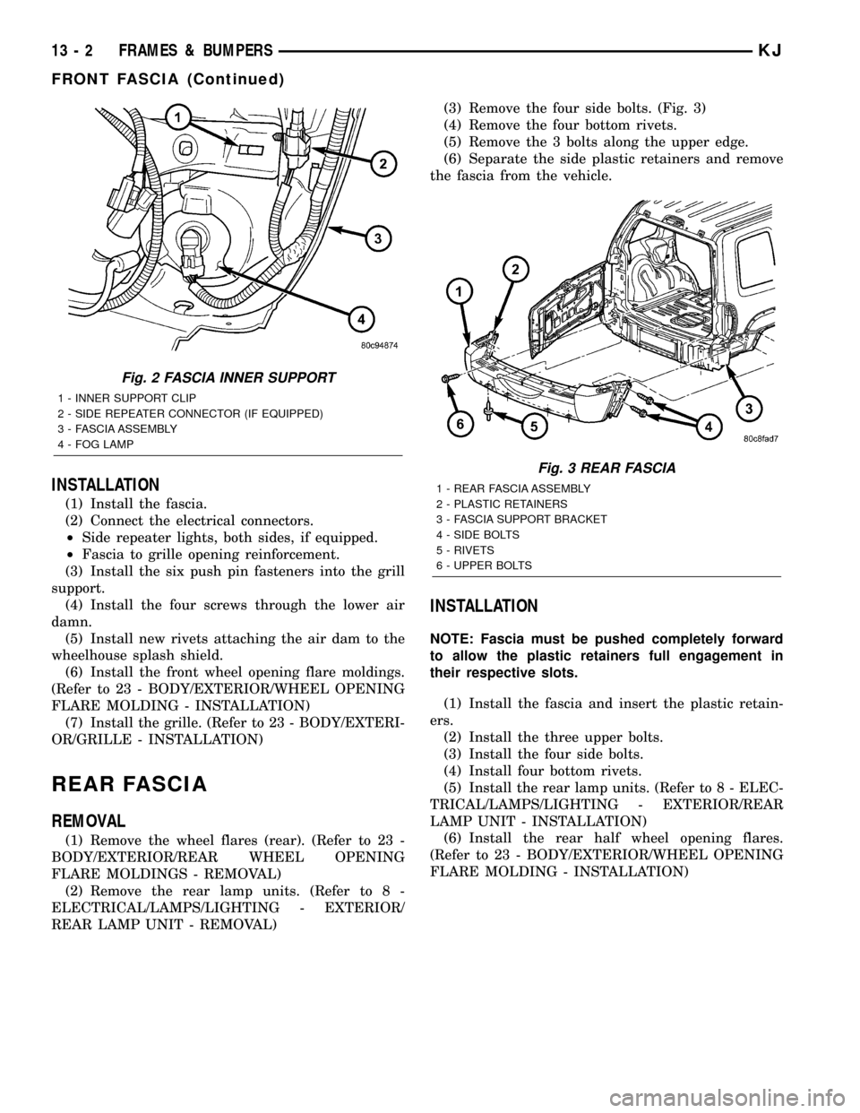
REAR LAMP UNIT - REMOVAL)(3) Remove the four side bolts. (Fig. 3)
(4) Remove the four bottom rivets.
(5) Remove the 3 bolts along the upper edge.
(6) Separate the side plastic retainers and remove
the fascia from the vehicle.
INSTALLATION
NOTE: Fascia must be pushed completely forward
to allow the plastic retainers full engagement in
their respective slots.
(1) Install the fascia and insert the plastic retain-
ers.
(2) Install the three upper bolts.
(3) Install the four side bolts.
(4) Install four bottom rivets.
(5) Install the rear lamp units. (Refer to 8 - ELEC-
TRICAL/LAMPS/LIGHTING - EXTERIOR/REAR
LAMP UNIT - INSTALLATION)
(6) Install the rear half wheel opening flares.
(Refer to 23 - BODY/EXTERIOR/WHEEL OPENING
FLARE MOLDING - INSTALLATION)
Fig. 2 FASCIA INNER SUPPORT
1 - INNER SUPPORT CLIP
2 - SIDE REPEATER CONNECTOR (IF EQUIPPED)
3 - FASCIA ASSEMBLY
4 - FOG LAMP
Fig. 3 REAR FASCIA
1 - REAR FASCIA ASSEMBLY
2 - PLASTIC RETAINERS
3 - FASCIA SUPPORT BRACKET
4 - SIDE BOLTS
5 - RIVETS
6 - UPPER BOLTS
13 - 2 FRAMES & BUMPERSKJ
FRONT FASCIA (Continued)
Page 1387 of 1803
SPECIFICATIONS
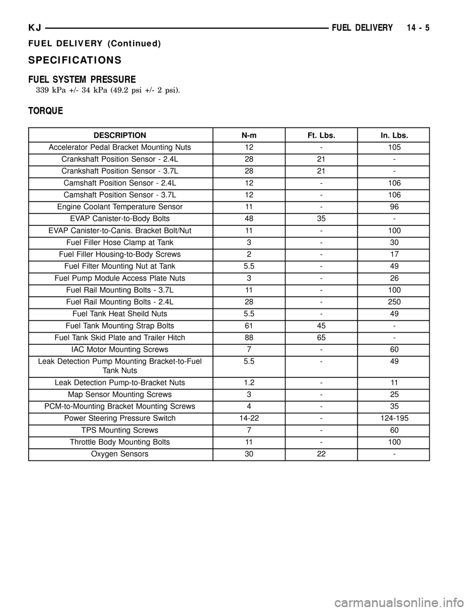
FUEL SYSTEM PRESSURE
339 kPa +/- 34 kPa (49.2 psi +/- 2 psi).
TORQUE
DESCRIPTION N-m Ft. Lbs. In. Lbs.
Accelerator Pedal Bracket Mounting Nuts 12 - 105
Crankshaft Position Sensor - 2.4L 28 21 -
Crankshaft Position Sensor - 3.7L 28 21 -
Camshaft Position Sensor - 2.4L 12 - 106
Camshaft Position Sensor - 3.7L 12 - 106
Engine Coolant Temperature Sensor 11 - 96
EVAP Canister-to-Body Bolts 48 35 -
EVAP Canister-to-Canis. Bracket Bolt/Nut 11 - 100
Fuel Filler Hose Clamp at Tank 3 - 30
Fuel Filler Housing-to-Body Screws 2 - 17
Fuel Filter Mounting Nut at Tank 5.5 - 49
Fuel Pump Module Access Plate Nuts 3 - 26
Fuel Rail Mounting Bolts - 3.7L 11 - 100
Fuel Rail Mounting Bolts - 2.4L 28 - 250
Fuel Tank Heat Sheild Nuts 5.5 - 49
Fuel Tank Mounting Strap Bolts 61 45 -
Fuel Tank Skid Plate and Trailer Hitch 88 65 -
IAC Motor Mounting Screws 7 - 60
Leak Detection Pump Mounting Bracket-to-Fuel
Tank Nuts5.5 - 49
Leak Detection Pump-to-Bracket Nuts 1.2 - 11
Map Sensor Mounting Screws 3 - 25
PCM-to-Mounting Bracket Mounting Screws 4 - 35
Power Steering Pressure Switch 14-22 - 124-195
TPS Mounting Screws 7 - 60
Throttle Body Mounting Bolts 11 - 100
Oxygen Sensors 30 22 -
KJFUEL DELIVERY 14 - 5
FUEL DELIVERY (Continued)
Page 1389 of 1803
(3) Remove 4 fuel pump module access plate nuts
(Fig. 3).
(4) While applying heat from a heat gun, carefully
pry up fuel pump module access plate. Take care not
to bend plate.
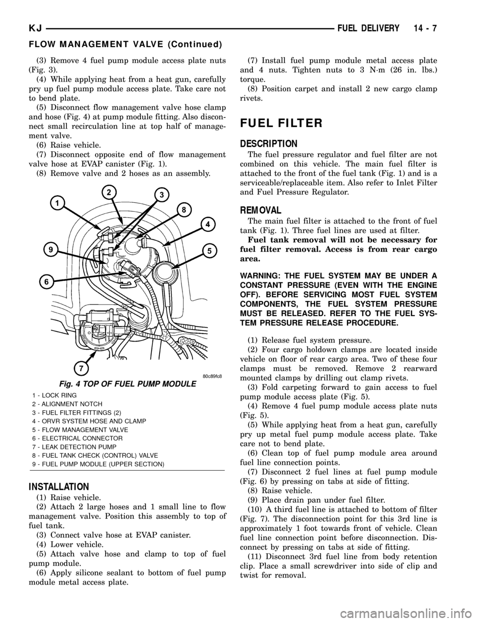
(5) Disconnect flow management valve hose clamp
and hose (Fig. 4) at pump module fitting. Also discon-
nect small recirculation line at top half of manage-
ment valve.
(6) Raise vehicle.
(7) Disconnect opposite end of flow management
valve hose at EVAP canister (Fig. 1).
(8) Remove valve and 2 hoses as an assembly.
INSTALLATION
(1) Raise vehicle.
(2) Attach 2 large hoses and 1 small line to flow
management valve. Position this assembly to top of
fuel tank.
(3) Connect valve hose at EVAP canister.
(4) Lower vehicle.
(5) Attach valve hose and clamp to top of fuel
pump module.
(6) Apply silicone sealant to bottom of fuel pump
module metal access plate.(7) Install fuel pump module metal access plate
and 4 nuts. Tighten nuts to 3 N´m (26 in. lbs.)
torque.
(8) Position carpet and install 2 new cargo clamp
rivets.
FUEL FILTER
DESCRIPTION
The fuel pressure regulator and fuel filter are not
combined on this vehicle. The main fuel filter is
attached to the front of the fuel tank (Fig. 1) and is a
serviceable/replaceable item. Also refer to Inlet Filter
and Fuel Pressure Regulator.
REMOVAL
The main fuel filter is attached to the front of fuel
tank (Fig. 1). Three fuel lines are used at filter.
Fuel tank removal will not be necessary for
fuel filter removal. Access is from rear cargo
area.
WARNING: THE FUEL SYSTEM MAY BE UNDER A
CONSTANT PRESSURE (EVEN WITH THE ENGINE
OFF). BEFORE SERVICING MOST FUEL SYSTEM
COMPONENTS, THE FUEL SYSTEM PRESSURE
MUST BE RELEASED. REFER TO THE FUEL SYS-
TEM PRESSURE RELEASE PROCEDURE.
(1) Release fuel system pressure.
(2) Four cargo holdown clamps are located inside
vehicle on floor of rear cargo area. Two of these four
clamps must be removed. Remove 2 rearward
mounted clamps by drilling out clamp rivets.
(3) Fold carpeting forward to gain access to fuel
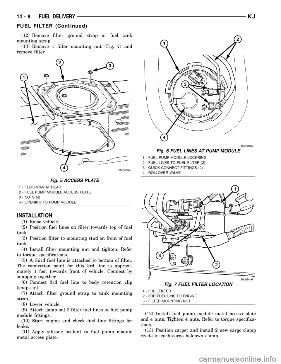
pump module access plate (Fig. 5).
(4) Remove 4 fuel pump module access plate nuts
(Fig. 5).
(5) While applying heat from a heat gun, carefully
pry up metal fuel pump module access plate. Take
care not to bend plate.
(6) Clean top of fuel pump module area around
fuel line connection points.
(7) Disconnect 2 fuel lines at fuel pump module
(Fig. 6) by pressing on tabs at side of fitting.
(8) Raise vehicle.
(9) Place drain pan under fuel filter.
(10) A third fuel line is attached to bottom of filter
(Fig. 7). The disconnection point for this 3rd line is
approximately 1 foot towards front of vehicle. Clean
fuel line connection point before disconnection. Dis-
connect by pressing on tabs at side of fitting.
(11) Disconnect 3rd fuel line from body retention
clip. Place a small screwdriver into side of clip and
twist for removal.
Fig. 4 TOP OF FUEL PUMP MODULE
1 - LOCK RING
2 - ALIGNMENT NOTCH
3 - FUEL FILTER FITTINGS (2)
4 - ORVR SYSTEM HOSE AND CLAMP
5 - FLOW MANAGEMENT VALVE
6 - ELECTRICAL CONNECTOR
7 - LEAK DETECTION PUMP
8 - FUEL TANK CHECK (CONTROL) VALVE
9 - FUEL PUMP MODULE (UPPER SECTION)
KJFUEL DELIVERY 14 - 7
FLOW MANAGEMENT VALVE (Continued)
Page 1390 of 1803
(12) Remove filter ground strap at fuel tank
mounting strap.
(13) Remove 1 filter mounting nut (Fig. 7) and
remove filter.
INSTALLATION
(1) Raise vehicle.
(2) Position fuel lines on filter towards top of fuel
tank.
(3) Position filter to mounting stud on front of fuel
tank.
(4) Install filter mounting nut and tighten. Refer
to torque specifications.
(5) A third fuel line is attached to bottom of filter.
The connection point for this 3rd line is approxi-
mately 1 foot towards front of vehicle. Connect by
snapping together.
(6) Connect 3rd fuel line to body retention clip
(snaps in).
(7) Attach filter ground strap to tank mounting
strap.
(8) Lower vehicle.
(9) Attach (snap on) 2 filter fuel lines at fuel pump
module fittings.
(10) Start engine and check fuel line fittings for
leaks.
(11) Apply silicone sealant to fuel pump module
metal access plate.(12) Install fuel pump module metal access plate
and 4 nuts. Tighten 4 nuts. Refer to torque specifica-
tions.
(13) Position carpet and install 2 new cargo clamp
rivets in each cargo holdown clamp.
Fig. 5 ACCESS PLATE
1 - FLOORPAN AT REAR
2 - FUEL PUMP MODULE ACCESS PLATE
3 - NUTS (4)
4 - OPENING TO PUMP MODULE
Fig. 6 FUEL LINES AT PUMP MODULE
1 - FUEL PUMP MODULE LOCKRING
2 - FUEL LINES TO FUEL FILTER (2)
3 - QUICK-CONNECT FITTINGS (2)
4 - ROLLOVER VALVE
Fig. 7 FUEL FILTER LOCATION
1 - FUEL FILTER
2 - 3RD FUEL LINE TO ENGINE
3 - FILTER MOUNTING NUT
14 - 8 FUEL DELIVERYKJ
FUEL FILTER (Continued)
Page 1393 of 1803
CAUTION: The interior components (o-rings, spac-
ers) of some types of quick-connect fitting are not
serviced separately. If service parts are not avail-
able, do not attempt to repair a damaged fitting or
fuel line. If repair is necessary, replace complete
fuel line assembly.
(1) Perform fuel pressure release procedure. Refer
to Fuel Pressure Release Procedure.
(2) Disconnect negative battery cable from battery.
(3) Clean fitting of any foreign material before dis-
assembly.
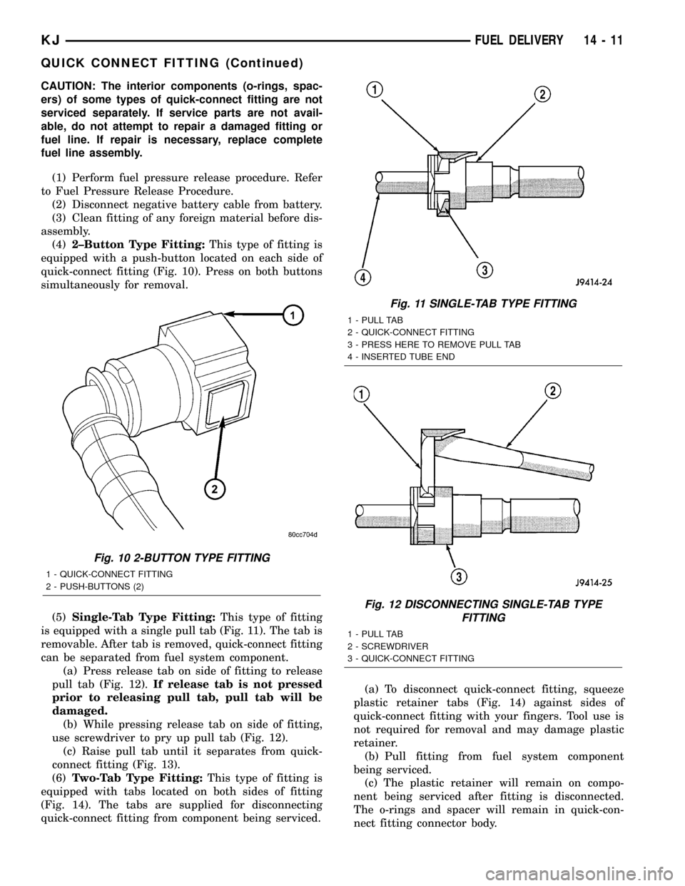
(4)2±Button Type Fitting:This type of fitting is
equipped with a push-button located on each side of
quick-connect fitting (Fig. 10). Press on both buttons
simultaneously for removal.
(5)Single-Tab Type Fitting:This type of fitting
is equipped with a single pull tab (Fig. 11). The tab is
removable. After tab is removed, quick-connect fitting
can be separated from fuel system component.
(a) Press release tab on side of fitting to release
pull tab (Fig. 12).If release tab is not pressed
prior to releasing pull tab, pull tab will be
damaged.
(b) While pressing release tab on side of fitting,
use screwdriver to pry up pull tab (Fig. 12).
(c) Raise pull tab until it separates from quick-
connect fitting (Fig. 13).
(6)Two-Tab Type Fitting:This type of fitting is
equipped with tabs located on both sides of fitting
(Fig. 14). The tabs are supplied for disconnecting
quick-connect fitting from component being serviced.(a) To disconnect quick-connect fitting, squeeze
plastic retainer tabs (Fig. 14) against sides of
quick-connect fitting with your fingers. Tool use is
not required for removal and may damage plastic
retainer.
(b) Pull fitting from fuel system component
being serviced.
(c) The plastic retainer will remain on compo-
nent being serviced after fitting is disconnected.
The o-rings and spacer will remain in quick-con-
nect fitting connector body.
Fig. 10 2-BUTTON TYPE FITTING
1 - QUICK-CONNECT FITTING
2 - PUSH-BUTTONS (2)
Fig. 11 SINGLE-TAB TYPE FITTING
1 - PULL TAB
2 - QUICK-CONNECT FITTING
3 - PRESS HERE TO REMOVE PULL TAB
4 - INSERTED TUBE END
Fig. 12 DISCONNECTING SINGLE-TAB TYPE
FITTING
1 - PULL TAB
2 - SCREWDRIVER
3 - QUICK-CONNECT FITTING
KJFUEL DELIVERY 14 - 11
QUICK CONNECT FITTING (Continued)
Page 1394 of 1803
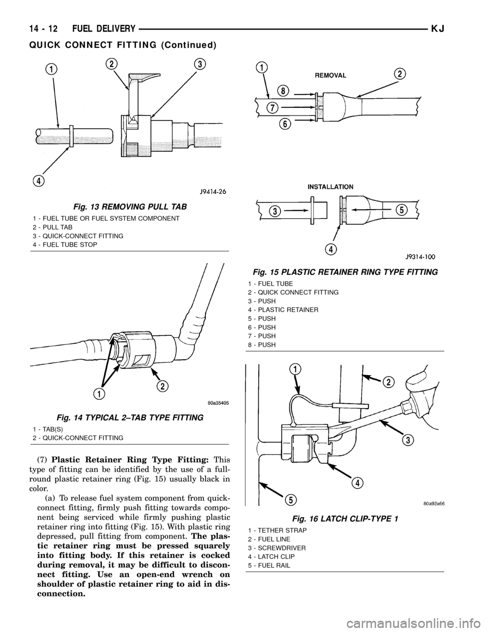
(7)Plastic Retainer Ring Type Fitting:This
type of fitting can be identified by the use of a full-
round plastic retainer ring (Fig. 15) usually black in
color.
(a) To release fuel system component from quick-
connect fitting, firmly push fitting towards compo-
nent being serviced while firmly pushing plastic
retainer ring into fitting (Fig. 15). With plastic ring
depressed, pull fitting from component.The plas-
tic retainer ring must be pressed squarely
into fitting body. If this retainer is cocked
during removal, it may be difficult to discon-
nect fitting. Use an open-end wrench on
shoulder of plastic retainer ring to aid in dis-
connection.
Fig. 13 REMOVING PULL TAB
1 - FUEL TUBE OR FUEL SYSTEM COMPONENT
2 - PULL TAB
3 - QUICK-CONNECT FITTING
4 - FUEL TUBE STOP
Fig. 14 TYPICAL 2±TAB TYPE FITTING
1 - TAB(S)
2 - QUICK-CONNECT FITTING
Fig. 15 PLASTIC RETAINER RING TYPE FITTING
1 - FUEL TUBE
2 - QUICK CONNECT FITTING
3 - PUSH
4 - PLASTIC RETAINER
5 - PUSH
6 - PUSH
7 - PUSH
8 - PUSH
Fig. 16 LATCH CLIP-TYPE 1
1 - TETHER STRAP
2 - FUEL LINE
3 - SCREWDRIVER
4 - LATCH CLIP
5 - FUEL RAIL
14 - 12 FUEL DELIVERYKJ
QUICK CONNECT FITTING (Continued)
Page 1395 of 1803
(b) After disconnection, plastic retainer ring will
remain with quick-connect fitting connector body.
(c) Inspect fitting connector body, plastic retainer
ring and fuel system component for damage.
Replace as necessary.
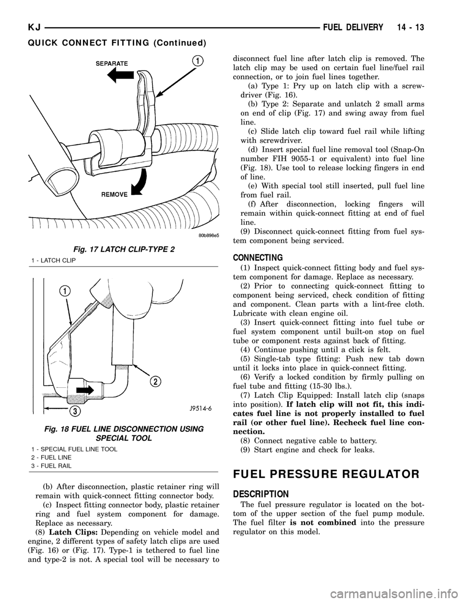
(8)Latch Clips:Depending on vehicle model and
engine, 2 different types of safety latch clips are used
(Fig. 16) or (Fig. 17). Type-1 is tethered to fuel line
and type-2 is not. A special tool will be necessary todisconnect fuel line after latch clip is removed. The
latch clip may be used on certain fuel line/fuel rail
connection, or to join fuel lines together.
(a) Type 1: Pry up on latch clip with a screw-
driver (Fig. 16).
(b) Type 2: Separate and unlatch 2 small arms
on end of clip (Fig. 17) and swing away from fuel
line.
(c) Slide latch clip toward fuel rail while lifting
with screwdriver.
(d) Insert special fuel line removal tool (Snap-On
number FIH 9055-1 or equivalent) into fuel line
(Fig. 18). Use tool to release locking fingers in end
of line.
(e) With special tool still inserted, pull fuel line
from fuel rail.
(f) After disconnection, locking fingers will
remain within quick-connect fitting at end of fuel
line.
(9) Disconnect quick-connect fitting from fuel sys-
tem component being serviced.
CONNECTING
(1) Inspect quick-connect fitting body and fuel sys-
tem component for damage. Replace as necessary.
(2) Prior to connecting quick-connect fitting to
component being serviced, check condition of fitting
and component. Clean parts with a lint-free cloth.
Lubricate with clean engine oil.
(3) Insert quick-connect fitting into fuel tube or
fuel system component until built-on stop on fuel
tube or component rests against back of fitting.
(4) Continue pushing until a click is felt.
(5) Single-tab type fitting: Push new tab down
until it locks into place in quick-connect fitting.
(6) Verify a locked condition by firmly pulling on
fuel tube and fitting (15-30 lbs.).
(7) Latch Clip Equipped: Install latch clip (snaps
into position).If latch clip will not fit, this indi-
cates fuel line is not properly installed to fuel
rail (or other fuel line). Recheck fuel line con-
nection.
(8) Connect negative cable to battery.
(9) Start engine and check for leaks.
FUEL PRESSURE REGULATOR
DESCRIPTION
The fuel pressure regulator is located on the bot-
tom of the upper section of the fuel pump module.
The fuel filteris not combinedinto the pressure
regulator on this model.
Fig. 17 LATCH CLIP-TYPE 2
1 - LATCH CLIP
Fig. 18 FUEL LINE DISCONNECTION USING
SPECIAL TOOL
1 - SPECIAL FUEL LINE TOOL
2 - FUEL LINE
3 - FUEL RAIL
KJFUEL DELIVERY 14 - 13
QUICK CONNECT FITTING (Continued)
Page 1404 of 1803
of the firing of the fuel injectors. It isnot usedas a
fuel pressure regulator. The fuel pressure regulator is
not mountedto the fuel rail on any engine. It is
located on the fuel tank mounted fuel pump module.
Refer to Fuel Pressure Regulator for additional infor-
mation.
The fuel rail is not repairable.
A quick-connect fitting with a safety latch is used
to attach the fuel line to the fuel rail.
3.7L
High pressure fuel from the fuel pump is routed to
the fuel rail. The fuel rail then supplies the neces-
sary fuel to each individual fuel injector.
A quick-connect fitting with a safety latch is used
to attach the fuel line to the fuel rail.
The fuel rail is not repairable.
REMOVAL
2.4L
WARNING: THE FUEL SYSTEM IS UNDER CON-
STANT PRESSURE EVEN WITH ENGINE OFF.
BEFORE SERVICING FUEL RAIL, FUEL SYSTEM
PRESSURE MUST BE RELEASED.
The fuel rail can be removed without removing the
intake manifold if the following procedures are fol-
lowed.(1) Remove fuel tank filler tube cap.
(2) Perform Fuel System Pressure Release Proce-
dure.
(3) Remove negative battery cable at battery.
(4) Remove air duct at throttle body.
(5) Disconnect fuel line latch clip and fuel line at
fuel rail. A special tool will be necessary for fuel line
disconnection. Refer to Quick-Connect Fittings.
(6) Remove necessary vacuum lines at throttle
body.
(7) Drain engine coolant and remove thermostat
and thermostat housing.
(8) Remove PCV hose and valve at valve cover.
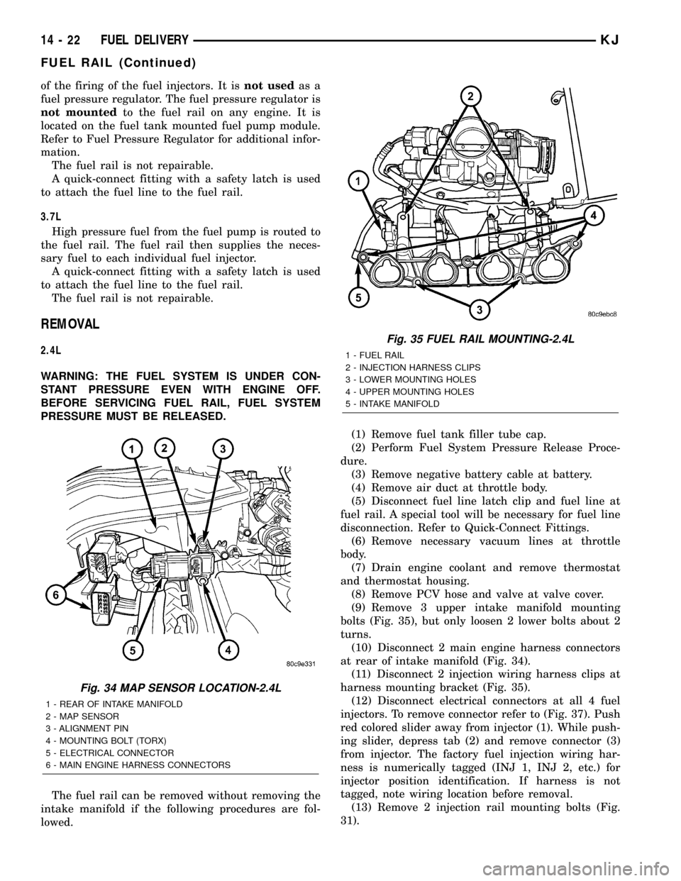
(9) Remove 3 upper intake manifold mounting
bolts (Fig. 35), but only loosen 2 lower bolts about 2
turns.
(10) Disconnect 2 main engine harness connectors
at rear of intake manifold (Fig. 34).
(11) Disconnect 2 injection wiring harness clips at
harness mounting bracket (Fig. 35).
(12) Disconnect electrical connectors at all 4 fuel
injectors. To remove connector refer to (Fig. 37). Push
red colored slider away from injector (1). While push-
ing slider, depress tab (2) and remove connector (3)
from injector. The factory fuel injection wiring har-
ness is numerically tagged (INJ 1, INJ 2, etc.) for
injector position identification. If harness is not
tagged, note wiring location before removal.
(13) Remove 2 injection rail mounting bolts (Fig.
31).
Fig. 34 MAP SENSOR LOCATION-2.4L
1 - REAR OF INTAKE MANIFOLD
2 - MAP SENSOR
3 - ALIGNMENT PIN
4 - MOUNTING BOLT (TORX)
5 - ELECTRICAL CONNECTOR
6 - MAIN ENGINE HARNESS CONNECTORS
Fig. 35 FUEL RAIL MOUNTING-2.4L
1 - FUEL RAIL
2 - INJECTION HARNESS CLIPS
3 - LOWER MOUNTING HOLES
4 - UPPER MOUNTING HOLES
5 - INTAKE MANIFOLD
14 - 22 FUEL DELIVERYKJ
FUEL RAIL (Continued)