2002 JEEP LIBERTY turn
[x] Cancel search: turnPage 1148 of 1803
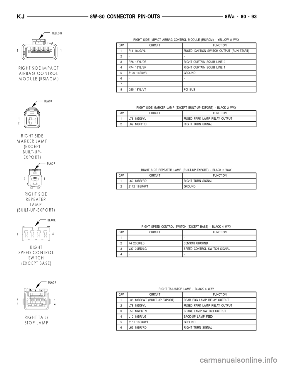
RIGHT SIDE IMPACT AIRBAG CONTROL MODULE (RSIACM) - YELLOW 8 WAY
CAV CIRCUIT FUNCTION
1 F14 18LG/YL FUSED IGNITION SWITCH OUTPUT (RUN-START)
2- -
3 R76 18YL/DB RIGHT CURTAIN SQUIB LINE 2
4 R74 18YL/BR RIGHT CURTAIN SQUIB LINE 1
5 Z100 18BK/YL GROUND
6- -
7- -
8 D25 18YL/VT PCI BUS
RIGHT SIDE MARKER LAMP (EXCEPT BUILT-UP-EXPORT) - BLACK 2 WAY
CAV CIRCUIT FUNCTION
1 L78 18DG/YL FUSED PARK LAMP RELAY OUTPUT
2 L62 18BR/RD RIGHT TURN SIGNAL
RIGHT SIDE REPEATER LAMP (BUILT-UP-EXPORT) - BLACK 2 WAY
CAV CIRCUIT FUNCTION
1 L62 18BR/RD RIGHT TURN SIGNAL
2 Z142 18BK/WT GROUND
RIGHT SPEED CONTROL SWITCH (EXCEPT BASE) - BLACK 4 WAY
CAV CIRCUIT FUNCTION
1- -
2 K4 20BK/LB SENSOR GROUND
3 V37 20RD/LG SPEED CONTROL SWITCH SIGNAL
4- -
RIGHT TAIL/STOP LAMP - BLACK 6 WAY
CAV CIRCUIT FUNCTION
1 L38 18BR/WT (BUILT-UP-EXPORT) REAR FOG LAMP RELAY OUTPUT
2 L78 18DG/YL FUSED PARK LAMP RELAY OUTPUT
3 L50 18WT/TN BRAKE LAMP SWITCH OUTPUT
4 L10 18BR/LG BACK-UP LAMP FEED
5 Z151 18BK/WT GROUND
6 L62 18BR/RD RIGHT TURN SIGNAL
KJ8W-80 CONNECTOR PIN-OUTS8Wa-80-93
Page 1151 of 1803
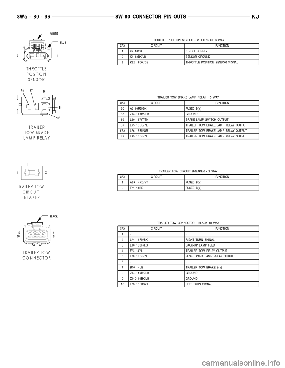
THROTTLE POSITION SENSOR - WHITE/BLUE 3 WAY
CAV CIRCUIT FUNCTION
1 K7 18OR 5 VOLT SUPPLY
2 K4 18BK/LB SENSOR GROUND
3 K22 18OR/DB THROTTLE POSITION SENSOR SIGNAL
TRAILER TOW BRAKE LAMP RELAY-5WAY
CAV CIRCUIT FUNCTION
30 A6 16RD/BK FUSED B(+)
85 Z149 18BK/LB GROUND
86 L50 18WT/TN BRAKE LAMP SWITCH OUTPUT
87 L95 16DG/YL TRAILER TOW BRAKE LAMP RELAY OUTPUT
87A L76 16BK/OR TRAILER TOW BRAKE LAMP RELAY OUTPUT
87 L95 16DG/YL TRAILER TOW BRAKE LAMP RELAY OUTPUT
TRAILER TOW CIRCUIT BREAKER-2WAY
CAV CIRCUIT FUNCTION
1 A99 14RD/VT FUSED B(+)
2 F71 14RD FUSED B(+)
TRAILER TOW CONNECTOR - BLACK 10 WAY
CAV CIRCUIT FUNCTION
1- -
2 L74 16PK/BK RIGHT TURN SIGNAL
3 L10 18BR/LG BACK-UP LAMP FEED
4 F73 14YL TRAILER TOW RELAY OUTPUT
5 L78 18DG/YL FUSED PARK LAMP RELAY OUTPUT
6- -
7 B40 14LB TRAILER TOW BRAKE B(+)
8 Z149 16BK/LB GROUND
9 Z149 16BK/LB GROUND
10 L73 16PK/WT LEFT TURN SIGNAL
8Wa - 80 - 96 8W-80 CONNECTOR PIN-OUTSKJ
Page 1152 of 1803
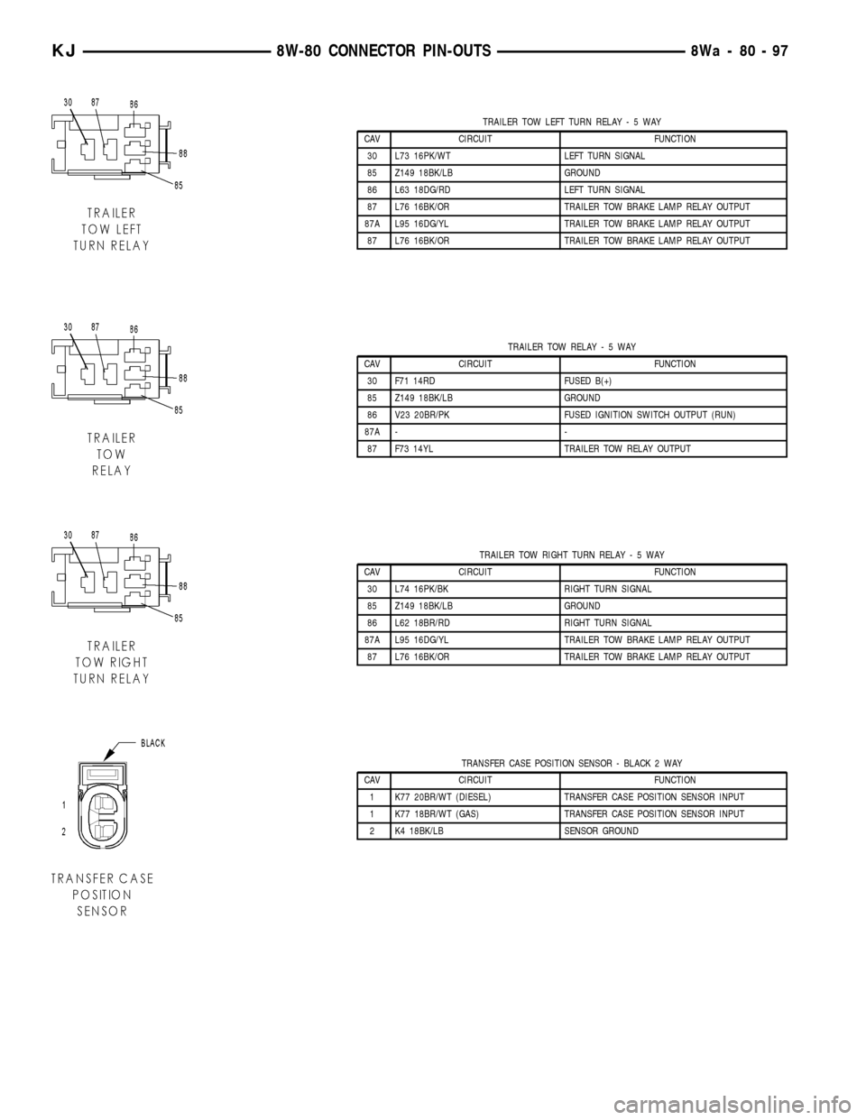
TRAILER TOW LEFT TURN RELAY-5WAY
CAV CIRCUIT FUNCTION
30 L73 16PK/WT LEFT TURN SIGNAL
85 Z149 18BK/LB GROUND
86 L63 18DG/RD LEFT TURN SIGNAL
87 L76 16BK/OR TRAILER TOW BRAKE LAMP RELAY OUTPUT
87A L95 16DG/YL TRAILER TOW BRAKE LAMP RELAY OUTPUT
87 L76 16BK/OR TRAILER TOW BRAKE LAMP RELAY OUTPUT
TRAILER TOW RELAY-5WAY
CAV CIRCUIT FUNCTION
30 F71 14RD FUSED B(+)
85 Z149 18BK/LB GROUND
86 V23 20BR/PK FUSED IGNITION SWITCH OUTPUT (RUN)
87A - -
87 F73 14YL TRAILER TOW RELAY OUTPUT
TRAILER TOW RIGHT TURN RELAY-5WAY
CAV CIRCUIT FUNCTION
30 L74 16PK/BK RIGHT TURN SIGNAL
85 Z149 18BK/LB GROUND
86 L62 18BR/RD RIGHT TURN SIGNAL
87A L95 16DG/YL TRAILER TOW BRAKE LAMP RELAY OUTPUT
87 L76 16BK/OR TRAILER TOW BRAKE LAMP RELAY OUTPUT
TRANSFER CASE POSITION SENSOR - BLACK 2 WAY
CAV CIRCUIT FUNCTION
1 K77 20BR/WT (DIESEL) TRANSFER CASE POSITION SENSOR INPUT
1 K77 18BR/WT (GAS) TRANSFER CASE POSITION SENSOR INPUT
2 K4 18BK/LB SENSOR GROUND
KJ8W-80 CONNECTOR PIN-OUTS8Wa-80-97
Page 1161 of 1803
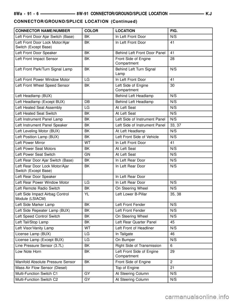
CONNECTOR NAME/NUMBER COLOR LOCATION FIG.
Left Front Door Ajar Switch (Base) BK In Left Front Door N/S
Left Front Door Lock Motor/Ajar
Switch (Except Base)BK In Left Front Door 41
Left Front Door Speaker BK Behind Left Front Door Panel 41
Left Front Impact Sensor BK Front Side of Engine
Compartment28
Left Front Park/Turn Signal Lamp BK Behind Left Turn Signal
LampN/S
Left Front Power Window Motor LG In Left Front Door 41
Left Front Wheel Speed Sensor BK Left Side of Engine
Compartment30
Left Headlamp (BUX) Behind Left Headlamp N/S
Left Headlamp (Except BUX) DB Behind Left Headlamp N/S
Left Heated Seat Assembly LG At Left Seat N/S
Left Heated Seat Switch BK At Left Seat N/S
Left Instrument Panel Lamp BK Left Side of Instrument Panel N/S
Left Instrument Panel Speaker BK Left Side of Instrument Panel 33, 37
Left Leveling Motor (BUX) BK At Left Headlamp N/S
Left Position Lamp (BUX) BK Left Front Side of Vehicle N/S
Left Power Mirror WT In Left Front Door 41
Left Power Seat Motors BK At Left Seat N/S
Left Power Seat Switch GN At Left Seat N/S
Left Rear Door Ajar Switch (Base) BK In Left Rear Door N/S
Left Rear Door Lock Motor/Ajar
Switch (Except Base)BK In Left Rear Door N/S
Left Rear Door Speaker In Left Rear Door
Left Rear Power Window Motor LG In Left Rear Door N/S
Left Remote Radio Switch BK On Steering Wheel N/S
Left Side Impact Airbag Control
Module (LSIACM)YL Left Lower B-Pillar 35, 38
Left Side Marker Lamp BK Left Front Fender N/S
Left Side Repeater Lamp (BUX) BK Left Front Fender N/S
Left Speed Control Switch BK On Steering Wheel N/S
Left Tail/Stop Lamp BK Left Rear Quarter Panel 45
Left Visor/Vanity Lamp WT Left Front of Headliner N/S
License Lamp (BUX) LG In Tailgate 46
License Lamp (Except BUX) LG On Bumper N/S
Line Pressure Sensor (3.7L) BK Right Side of Transmission 6
Low Note Horn BK Left Front Side of Engine
Compartment29
Manifold Absolute Pressure Sensor BK Front Side of Engine 2
Mass Air Flow Sensor (Diesel) Top of Engine 21
Multi-Function Switch C1 GY At Steering Column N/S
Multi-Function Switch C2 GY At Steering Column N/S
8Wa - 91 - 6 8W-91 CONNECTOR/GROUND/SPLICE LOCATIONKJ
CONNECTOR/GROUND/SPLICE LOCATION (Continued)
Page 1163 of 1803
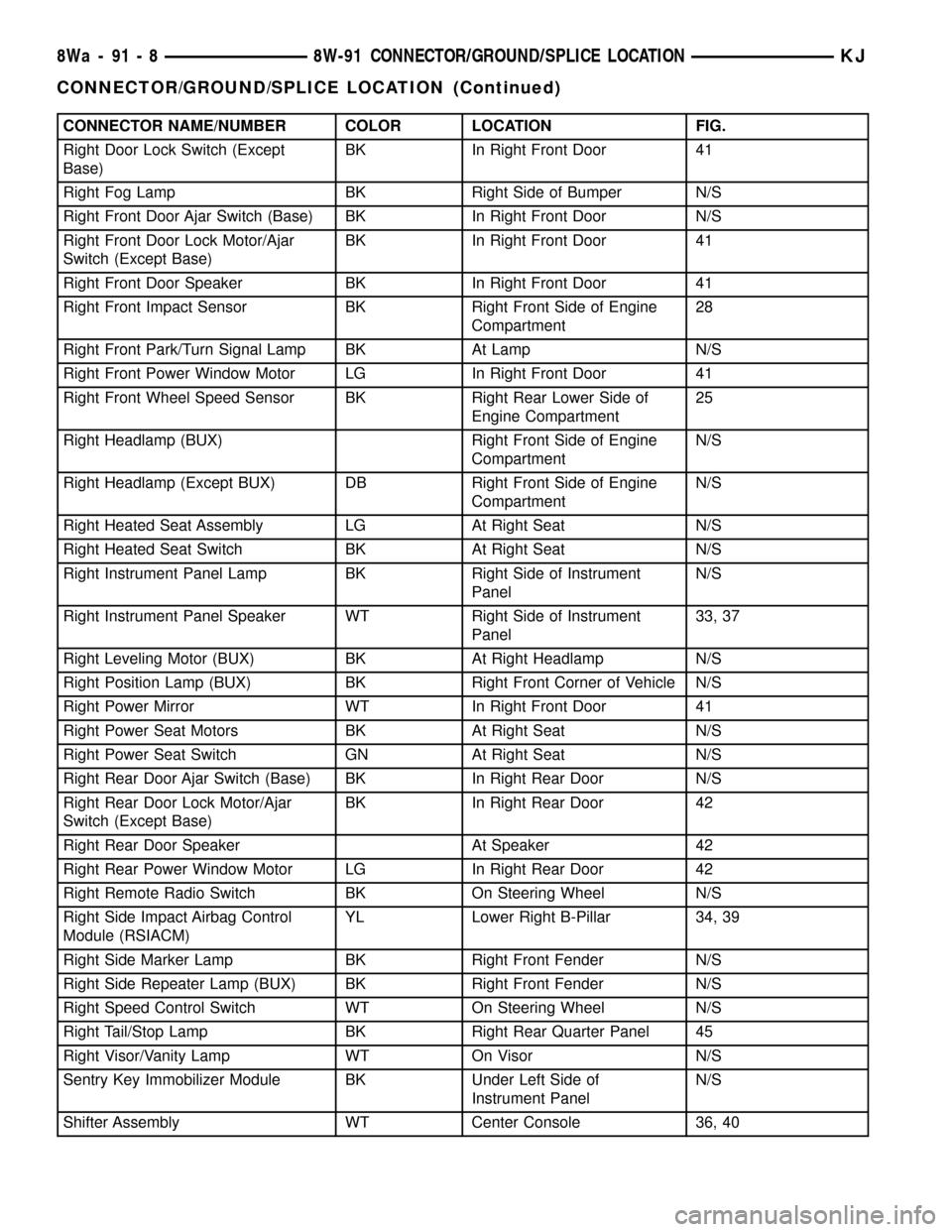
CONNECTOR NAME/NUMBER COLOR LOCATION FIG.
Right Door Lock Switch (Except
Base)BK In Right Front Door 41
Right Fog Lamp BK Right Side of Bumper N/S
Right Front Door Ajar Switch (Base) BK In Right Front Door N/S
Right Front Door Lock Motor/Ajar
Switch (Except Base)BK In Right Front Door 41
Right Front Door Speaker BK In Right Front Door 41
Right Front Impact Sensor BK Right Front Side of Engine
Compartment28
Right Front Park/Turn Signal Lamp BK At Lamp N/S
Right Front Power Window Motor LG In Right Front Door 41
Right Front Wheel Speed Sensor BK Right Rear Lower Side of
Engine Compartment25
Right Headlamp (BUX) Right Front Side of Engine
CompartmentN/S
Right Headlamp (Except BUX) DB Right Front Side of Engine
CompartmentN/S
Right Heated Seat Assembly LG At Right Seat N/S
Right Heated Seat Switch BK At Right Seat N/S
Right Instrument Panel Lamp BK Right Side of Instrument
PanelN/S
Right Instrument Panel Speaker WT Right Side of Instrument
Panel33, 37
Right Leveling Motor (BUX) BK At Right Headlamp N/S
Right Position Lamp (BUX) BK Right Front Corner of Vehicle N/S
Right Power Mirror WT In Right Front Door 41
Right Power Seat Motors BK At Right Seat N/S
Right Power Seat Switch GN At Right Seat N/S
Right Rear Door Ajar Switch (Base) BK In Right Rear Door N/S
Right Rear Door Lock Motor/Ajar
Switch (Except Base)BK In Right Rear Door 42
Right Rear Door Speaker At Speaker 42
Right Rear Power Window Motor LG In Right Rear Door 42
Right Remote Radio Switch BK On Steering Wheel N/S
Right Side Impact Airbag Control
Module (RSIACM)YL Lower Right B-Pillar 34, 39
Right Side Marker Lamp BK Right Front Fender N/S
Right Side Repeater Lamp (BUX) BK Right Front Fender N/S
Right Speed Control Switch WT On Steering Wheel N/S
Right Tail/Stop Lamp BK Right Rear Quarter Panel 45
Right Visor/Vanity Lamp WT On Visor N/S
Sentry Key Immobilizer Module BK Under Left Side of
Instrument PanelN/S
Shifter Assembly WT Center Console 36, 40
8Wa - 91 - 8 8W-91 CONNECTOR/GROUND/SPLICE LOCATIONKJ
CONNECTOR/GROUND/SPLICE LOCATION (Continued)
Page 1164 of 1803
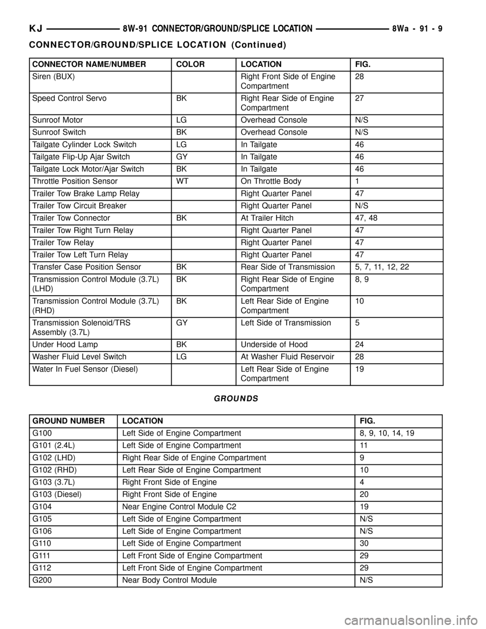
CONNECTOR NAME/NUMBER COLOR LOCATION FIG.
Siren (BUX) Right Front Side of Engine
Compartment28
Speed Control Servo BK Right Rear Side of Engine
Compartment27
Sunroof Motor LG Overhead Console N/S
Sunroof Switch BK Overhead Console N/S
Tailgate Cylinder Lock Switch LG In Tailgate 46
Tailgate Flip-Up Ajar Switch GY In Tailgate 46
Tailgate Lock Motor/Ajar Switch BK In Tailgate 46
Throttle Position Sensor WT On Throttle Body 1
Trailer Tow Brake Lamp Relay Right Quarter Panel 47
Trailer Tow Circuit Breaker Right Quarter Panel N/S
Trailer Tow Connector BK At Trailer Hitch 47, 48
Trailer Tow Right Turn Relay Right Quarter Panel 47
Trailer Tow Relay Right Quarter Panel 47
Trailer Tow Left Turn Relay Right Quarter Panel 47
Transfer Case Position Sensor BK Rear Side of Transmission 5, 7, 11, 12, 22
Transmission Control Module (3.7L)
(LHD)BK Right Rear Side of Engine
Compartment8, 9
Transmission Control Module (3.7L)
(RHD)BK Left Rear Side of Engine
Compartment10
Transmission Solenoid/TRS
Assembly (3.7L)GY Left Side of Transmission 5
Under Hood Lamp BK Underside of Hood 24
Washer Fluid Level Switch LG At Washer Fluid Reservoir 28
Water In Fuel Sensor (Diesel) Left Rear Side of Engine
Compartment19
GROUNDS
GROUND NUMBER LOCATION FIG.
G100 Left Side of Engine Compartment 8, 9, 10, 14, 19
G101 (2.4L) Left Side of Engine Compartment 11
G102 (LHD) Right Rear Side of Engine Compartment 9
G102 (RHD) Left Rear Side of Engine Compartment 10
G103 (3.7L) Right Front Side of Engine 4
G103 (Diesel) Right Front Side of Engine 20
G104 Near Engine Control Module C2 19
G105 Left Side of Engine Compartment N/S
G106 Left Side of Engine Compartment N/S
G110 Left Side of Engine Compartment 30
G111 Left Front Side of Engine Compartment 29
G112 Left Front Side of Engine Compartment 29
G200 Near Body Control Module N/S
KJ8W-91 CONNECTOR/GROUND/SPLICE LOCATION8Wa-91-9
CONNECTOR/GROUND/SPLICE LOCATION (Continued)
Page 1165 of 1803
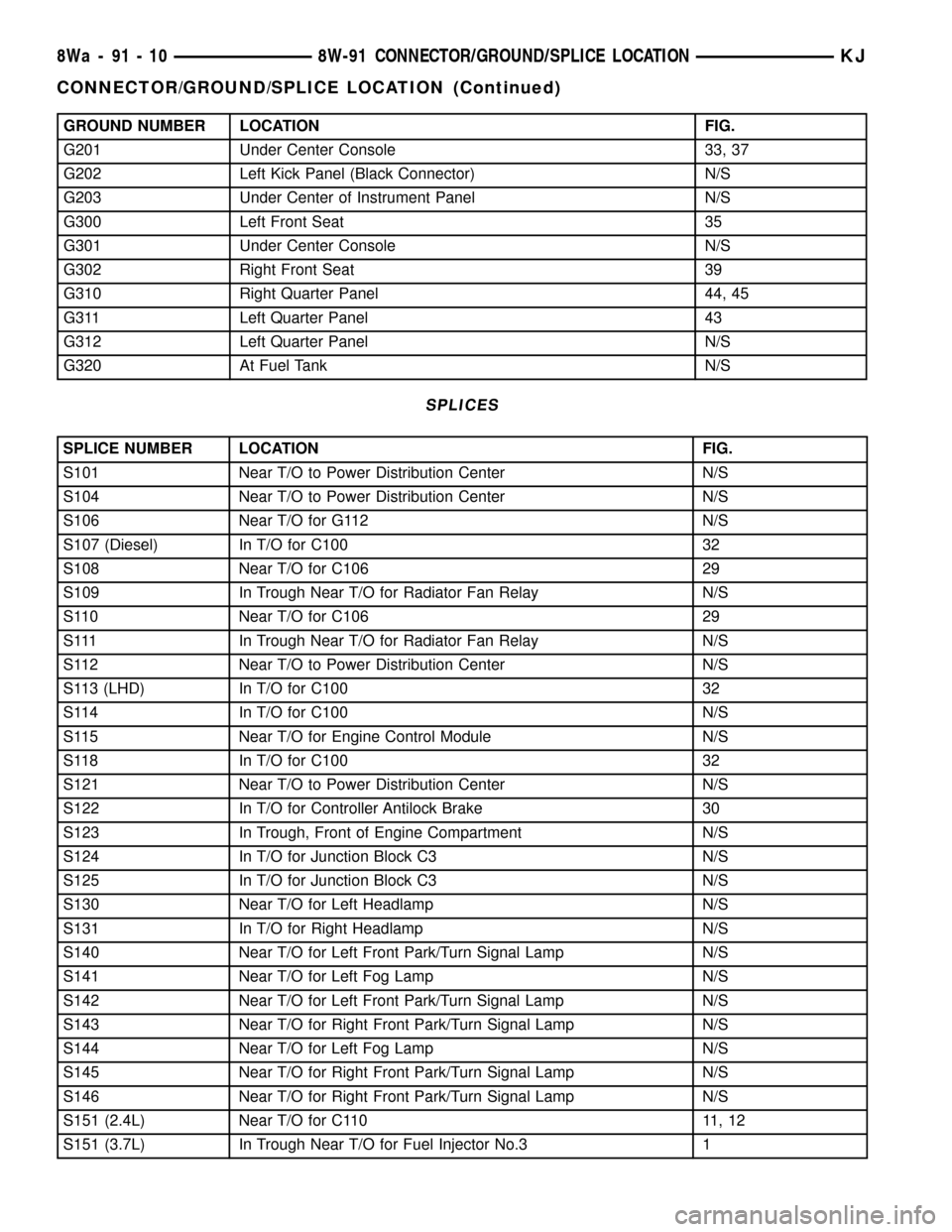
GROUND NUMBER LOCATION FIG.
G201 Under Center Console 33, 37
G202 Left Kick Panel (Black Connector) N/S
G203 Under Center of Instrument Panel N/S
G300 Left Front Seat 35
G301 Under Center Console N/S
G302 Right Front Seat 39
G310 Right Quarter Panel 44, 45
G311 Left Quarter Panel 43
G312 Left Quarter Panel N/S
G320 At Fuel Tank N/S
SPLICES
SPLICE NUMBER LOCATION FIG.
S101 Near T/O to Power Distribution Center N/S
S104 Near T/O to Power Distribution Center N/S
S106 Near T/O for G112 N/S
S107 (Diesel) In T/O for C100 32
S108 Near T/O for C106 29
S109 In Trough Near T/O for Radiator Fan Relay N/S
S110 Near T/O for C106 29
S111 In Trough Near T/O for Radiator Fan Relay N/S
S112 Near T/O to Power Distribution Center N/S
S113 (LHD) In T/O for C100 32
S114 In T/O for C100 N/S
S115 Near T/O for Engine Control Module N/S
S118 In T/O for C100 32
S121 Near T/O to Power Distribution Center N/S
S122 In T/O for Controller Antilock Brake 30
S123 In Trough, Front of Engine Compartment N/S
S124 In T/O for Junction Block C3 N/S
S125 In T/O for Junction Block C3 N/S
S130 Near T/O for Left Headlamp N/S
S131 In T/O for Right Headlamp N/S
S140 Near T/O for Left Front Park/Turn Signal Lamp N/S
S141 Near T/O for Left Fog Lamp N/S
S142 Near T/O for Left Front Park/Turn Signal Lamp N/S
S143 Near T/O for Right Front Park/Turn Signal Lamp N/S
S144 Near T/O for Left Fog Lamp N/S
S145 Near T/O for Right Front Park/Turn Signal Lamp N/S
S146 Near T/O for Right Front Park/Turn Signal Lamp N/S
S151 (2.4L) Near T/O for C110 11, 12
S151 (3.7L) In Trough Near T/O for Fuel Injector No.3 1
8Wa - 91 - 10 8W-91 CONNECTOR/GROUND/SPLICE LOCATIONKJ
CONNECTOR/GROUND/SPLICE LOCATION (Continued)
Page 1223 of 1803
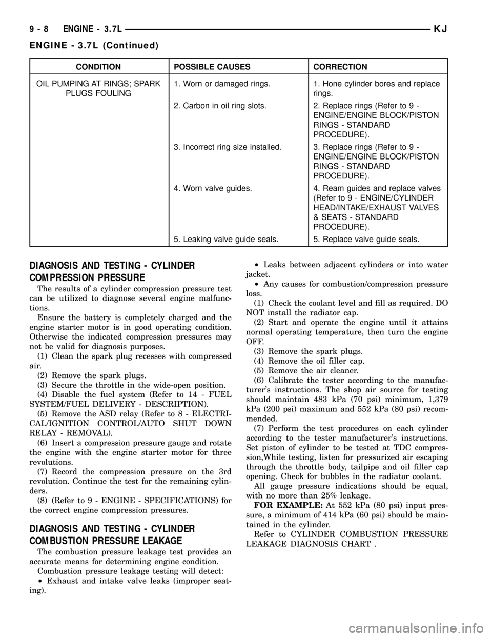
CONDITION POSSIBLE CAUSES CORRECTION
OIL PUMPING AT RINGS; SPARK
PLUGS FOULING1. Worn or damaged rings. 1. Hone cylinder bores and replace
rings.
2. Carbon in oil ring slots. 2. Replace rings (Refer to 9 -
ENGINE/ENGINE BLOCK/PISTON
RINGS - STANDARD
PROCEDURE).
3. Incorrect ring size installed. 3. Replace rings (Refer to 9 -
ENGINE/ENGINE BLOCK/PISTON
RINGS - STANDARD
PROCEDURE).
4. Worn valve guides. 4. Ream guides and replace valves
(Refer to 9 - ENGINE/CYLINDER
HEAD/INTAKE/EXHAUST VALVES
& SEATS - STANDARD
PROCEDURE).
5. Leaking valve guide seals. 5. Replace valve guide seals.
DIAGNOSIS AND TESTING - CYLINDER
COMPRESSION PRESSURE
The results of a cylinder compression pressure test
can be utilized to diagnose several engine malfunc-
tions.
Ensure the battery is completely charged and the
engine starter motor is in good operating condition.
Otherwise the indicated compression pressures may
not be valid for diagnosis purposes.
(1) Clean the spark plug recesses with compressed
air.
(2) Remove the spark plugs.
(3) Secure the throttle in the wide-open position.
(4) Disable the fuel system (Refer to 14 - FUEL
SYSTEM/FUEL DELIVERY - DESCRIPTION).
(5) Remove the ASD relay (Refer to 8 - ELECTRI-
CAL/IGNITION CONTROL/AUTO SHUT DOWN
RELAY - REMOVAL).
(6) Insert a compression pressure gauge and rotate
the engine with the engine starter motor for three
revolutions.
(7) Record the compression pressure on the 3rd
revolution. Continue the test for the remaining cylin-
ders.
(8) (Refer to 9 - ENGINE - SPECIFICATIONS) for
the correct engine compression pressures.
DIAGNOSIS AND TESTING - CYLINDER
COMBUSTION PRESSURE LEAKAGE
The combustion pressure leakage test provides an
accurate means for determining engine condition.
Combustion pressure leakage testing will detect:
²Exhaust and intake valve leaks (improper seat-
ing).²Leaks between adjacent cylinders or into water
jacket.
²Any causes for combustion/compression pressure
loss.
(1) Check the coolant level and fill as required. DO
NOT install the radiator cap.
(2) Start and operate the engine until it attains
normal operating temperature, then turn the engine
OFF.
(3) Remove the spark plugs.
(4) Remove the oil filler cap.
(5) Remove the air cleaner.
(6) Calibrate the tester according to the manufac-
turer's instructions. The shop air source for testing
should maintain 483 kPa (70 psi) minimum, 1,379
kPa (200 psi) maximum and 552 kPa (80 psi) recom-
mended.
(7) Perform the test procedures on each cylinder
according to the tester manufacturer's instructions.
Set piston of cylinder to be tested at TDC compres-
sion,While testing, listen for pressurized air escaping
through the throttle body, tailpipe and oil filler cap
opening. Check for bubbles in the radiator coolant.
All gauge pressure indications should be equal,
with no more than 25% leakage.
FOR EXAMPLE:At 552 kPa (80 psi) input pres-
sure, a minimum of 414 kPa (60 psi) should be main-
tained in the cylinder.
Refer to CYLINDER COMBUSTION PRESSURE
LEAKAGE DIAGNOSIS CHART .
9 - 8 ENGINE - 3.7LKJ
ENGINE - 3.7L (Continued)