2002 JEEP LIBERTY oil pressure sensor
[x] Cancel search: oil pressure sensorPage 1138 of 1803
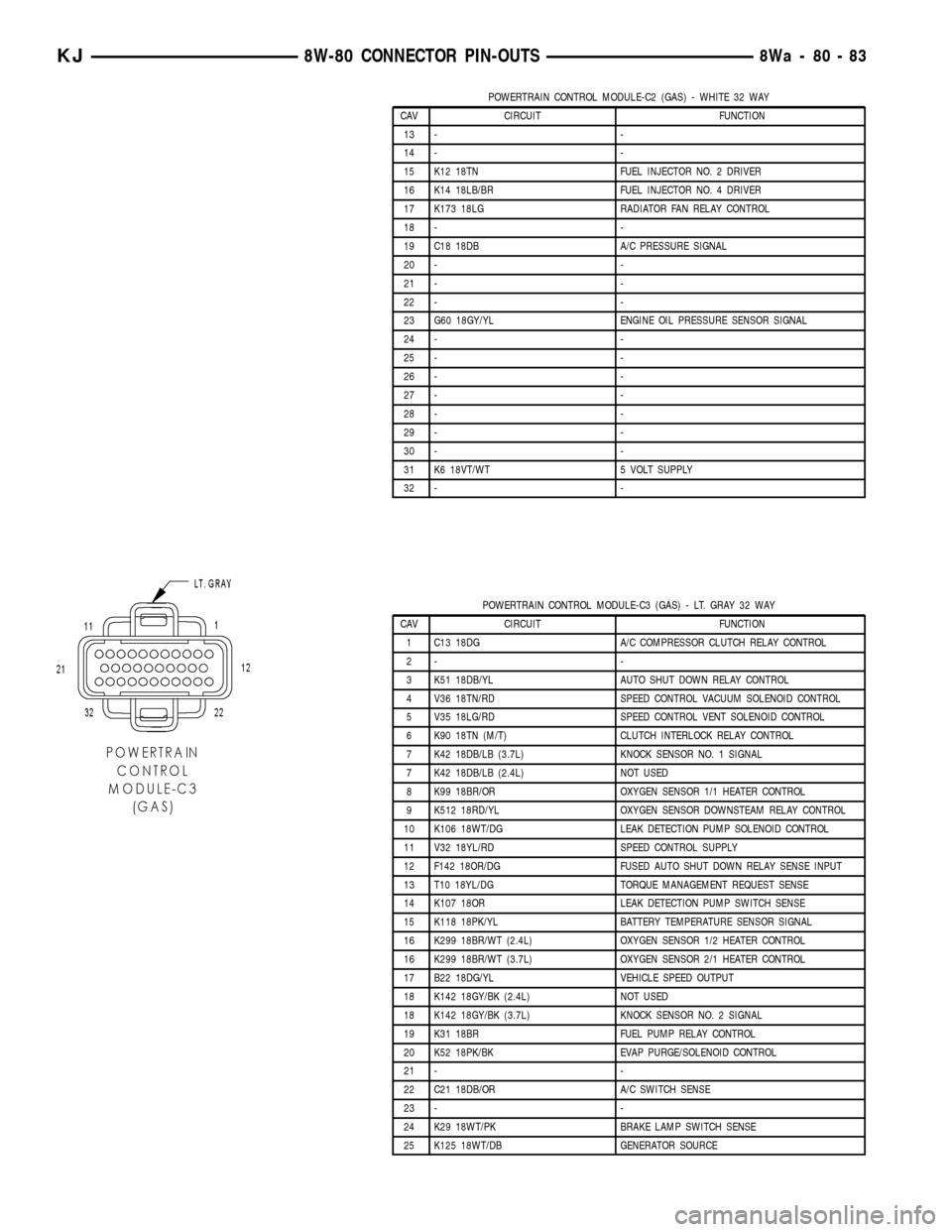
POWERTRAIN CONTROL MODULE-C2 (GAS) - WHITE 32 WAY
CAV CIRCUIT FUNCTION
13 - -
14 - -
15 K12 18TN FUEL INJECTOR NO. 2 DRIVER
16 K14 18LB/BR FUEL INJECTOR NO. 4 DRIVER
17 K173 18LG RADIATOR FAN RELAY CONTROL
18 - -
19 C18 18DB A/C PRESSURE SIGNAL
20 - -
21 - -
22 - -
23 G60 18GY/YL ENGINE OIL PRESSURE SENSOR SIGNAL
24 - -
25 - -
26 - -
27 - -
28 - -
29 - -
30 - -
31 K6 18VT/WT 5 VOLT SUPPLY
32 - -
POWERTRAIN CONTROL MODULE-C3 (GAS) - LT. GRAY 32 WAY
CAV CIRCUIT FUNCTION
1 C13 18DG A/C COMPRESSOR CLUTCH RELAY CONTROL
2- -
3 K51 18DB/YL AUTO SHUT DOWN RELAY CONTROL
4 V36 18TN/RD SPEED CONTROL VACUUM SOLENOID CONTROL
5 V35 18LG/RD SPEED CONTROL VENT SOLENOID CONTROL
6 K90 18TN (M/T) CLUTCH INTERLOCK RELAY CONTROL
7 K42 18DB/LB (3.7L) KNOCK SENSOR NO. 1 SIGNAL
7 K42 18DB/LB (2.4L) NOT USED
8 K99 18BR/OR OXYGEN SENSOR 1/1 HEATER CONTROL
9 K512 18RD/YL OXYGEN SENSOR DOWNSTEAM RELAY CONTROL
10 K106 18WT/DG LEAK DETECTION PUMP SOLENOID CONTROL
11 V32 18YL/RD SPEED CONTROL SUPPLY
12 F142 18OR/DG FUSED AUTO SHUT DOWN RELAY SENSE INPUT
13 T10 18YL/DG TORQUE MANAGEMENT REQUEST SENSE
14 K107 18OR LEAK DETECTION PUMP SWITCH SENSE
15 K118 18PK/YL BATTERY TEMPERATURE SENSOR SIGNAL
16 K299 18BR/WT (2.4L) OXYGEN SENSOR 1/2 HEATER CONTROL
16 K299 18BR/WT (3.7L) OXYGEN SENSOR 2/1 HEATER CONTROL
17 B22 18DG/YL VEHICLE SPEED OUTPUT
18 K142 18GY/BK (2.4L) NOT USED
18 K142 18GY/BK (3.7L) KNOCK SENSOR NO. 2 SIGNAL
19 K31 18BR FUEL PUMP RELAY CONTROL
20 K52 18PK/BK EVAP PURGE/SOLENOID CONTROL
21 - -
22 C21 18DB/OR A/C SWITCH SENSE
23 - -
24 K29 18WT/PK BRAKE LAMP SWITCH SENSE
25 K125 18WT/DB GENERATOR SOURCE
KJ8W-80 CONNECTOR PIN-OUTS8Wa-80-83
Page 1159 of 1803
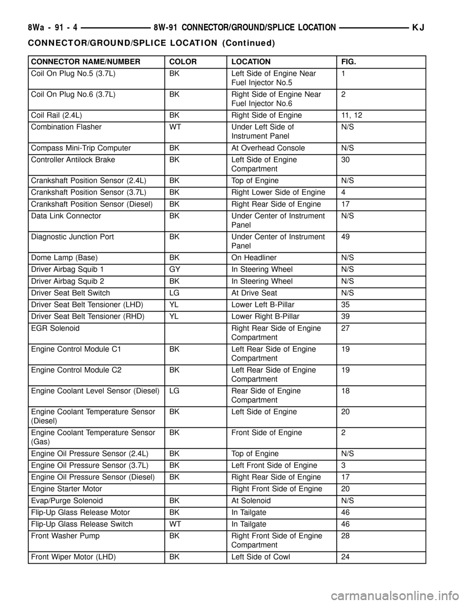
CONNECTOR NAME/NUMBER COLOR LOCATION FIG.
Coil On Plug No.5 (3.7L) BK Left Side of Engine Near
Fuel Injector No.51
Coil On Plug No.6 (3.7L) BK Right Side of Engine Near
Fuel Injector No.62
Coil Rail (2.4L) BK Right Side of Engine 11, 12
Combination Flasher WT Under Left Side of
Instrument PanelN/S
Compass Mini-Trip Computer BK At Overhead Console N/S
Controller Antilock Brake BK Left Side of Engine
Compartment30
Crankshaft Position Sensor (2.4L) BK Top of Engine N/S
Crankshaft Position Sensor (3.7L) BK Right Lower Side of Engine 4
Crankshaft Position Sensor (Diesel) BK Right Rear Side of Engine 17
Data Link Connector BK Under Center of Instrument
PanelN/S
Diagnostic Junction Port BK Under Center of Instrument
Panel49
Dome Lamp (Base) BK On Headliner N/S
Driver Airbag Squib 1 GY In Steering Wheel N/S
Driver Airbag Squib 2 BK In Steering Wheel N/S
Driver Seat Belt Switch LG At Drive Seat N/S
Driver Seat Belt Tensioner (LHD) YL Lower Left B-Pillar 35
Driver Seat Belt Tensioner (RHD) YL Lower Right B-Pillar 39
EGR Solenoid Right Rear Side of Engine
Compartment27
Engine Control Module C1 BK Left Rear Side of Engine
Compartment19
Engine Control Module C2 BK Left Rear Side of Engine
Compartment19
Engine Coolant Level Sensor (Diesel) LG Rear Side of Engine
Compartment18
Engine Coolant Temperature Sensor
(Diesel)BK Left Side of Engine 20
Engine Coolant Temperature Sensor
(Gas)BK Front Side of Engine 2
Engine Oil Pressure Sensor (2.4L) BK Top of Engine N/S
Engine Oil Pressure Sensor (3.7L) BK Left Front Side of Engine 3
Engine Oil Pressure Sensor (Diesel) BK Right Rear Side of Engine 17
Engine Starter Motor Right Front Side of Engine 20
Evap/Purge Solenoid BK At Solenoid N/S
Flip-Up Glass Release Motor BK In Tailgate 46
Flip-Up Glass Release Switch WT In Tailgate 46
Front Washer Pump BK Right Front Side of Engine
Compartment28
Front Wiper Motor (LHD) BK Left Side of Cowl 24
8Wa - 91 - 4 8W-91 CONNECTOR/GROUND/SPLICE LOCATIONKJ
CONNECTOR/GROUND/SPLICE LOCATION (Continued)
Page 1217 of 1803
ENGINE BLOCK
DESCRIPTION.........................39
STANDARD PROCEDURE - CYLINDER BORE
HONING............................39
CLEANING............................39
INSPECTION..........................40
CONNECTING ROD BEARINGS
STANDARD PROCEDURE - CONNECTING
ROD BEARING - FITTING...............40
CRANKSHAFT
DESCRIPTION.........................42
REMOVAL.............................43
INSPECTION..........................43
INSTALLATION.........................43
CRANKSHAFT MAIN BEARINGS
STANDARD PROCEDURE
MAIN BEARING - FITTING...............45
CRANKSHAFT OIL SEAL - FRONT
REMOVAL.............................46
INSTALLATION.........................47
CRANKSHAFT OIL SEAL - REAR
REMOVAL.............................48
INSTALLATION.........................48
FLEX PLATE
REMOVAL.............................49
INSTALLATION.........................49
PISTON & CONNECTING ROD
DESCRIPTION.........................49
STANDARD PROCEDURE
CONNECTING ROD BEARING - FITTING . . . 49
STANDARD PROCEDURE - PISTON
FITTING.............................50
REMOVAL.............................50
CLEANING............................51
INSPECTION..........................51
INSTALLATION.........................51
PISTON RINGS
STANDARD PROCEDURE - PISTON RING
FITTING.............................52
VIBRATION DAMPER
REMOVAL.............................54
INSTALLATION.........................55
STRUCTURAL COVER
DESCRIPTION.........................55
OPERATION...........................55
REMOVAL.............................55
INSTALLATION.........................55
FRONT MOUNT
REMOVAL.............................56
INSTALLATION.........................57
REAR MOUNT
REMOVAL.............................57
INSTALLATION.........................57
LUBRICATION
DESCRIPTION.........................57
OPERATION...........................58DIAGNOSIS AND TESTING
DIAGNOSIS AND TESTING - ENGINE OIL
LEAK...............................60
DIAGNOSIS AND TESTING - ENGINE OIL
PRESSURE..........................60
DIAGNOSIS AND TESTING - REAR SEAL
AREA LEAKS.........................61
OIL
STANDARD PROCEDURE - ENGINE OIL.....61
OIL FILTER
REMOVAL.............................63
INSTALLATION.........................63
OIL PAN
DESCRIPTION.........................63
REMOVAL.............................63
CLEANING............................63
INSPECTION..........................63
INSTALLATION.........................64
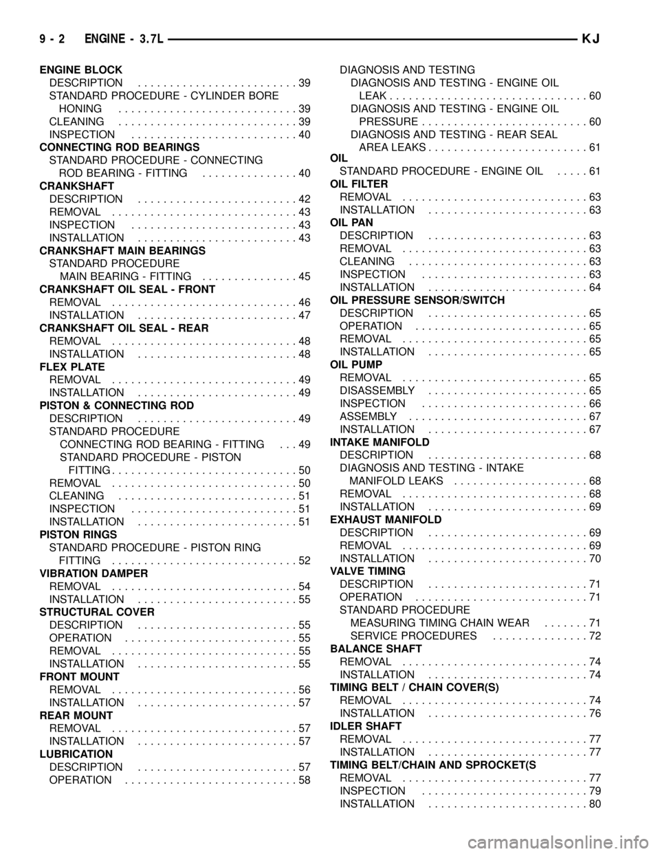
OIL PRESSURE SENSOR/SWITCH
DESCRIPTION.........................65
OPERATION...........................65
REMOVAL.............................65
INSTALLATION.........................65
OIL PUMP
REMOVAL.............................65
DISASSEMBLY.........................65
INSPECTION..........................66
ASSEMBLY............................67
INSTALLATION.........................67
INTAKE MANIFOLD
DESCRIPTION.........................68
DIAGNOSIS AND TESTING - INTAKE
MANIFOLD LEAKS.....................68
REMOVAL.............................68
INSTALLATION.........................69
EXHAUST MANIFOLD
DESCRIPTION.........................69
REMOVAL.............................69
INSTALLATION.........................70
VALVE TIMING
DESCRIPTION.........................71
OPERATION...........................71
STANDARD PROCEDURE
MEASURING TIMING CHAIN WEAR.......71
SERVICE PROCEDURES...............72
BALANCE SHAFT
REMOVAL.............................74
INSTALLATION.........................74
TIMING BELT / CHAIN COVER(S)
REMOVAL.............................74
INSTALLATION.........................76
IDLER SHAFT
REMOVAL.............................77
INSTALLATION.........................77
TIMING BELT/CHAIN AND SPROCKET(S
REMOVAL.............................77
INSPECTION..........................79
INSTALLATION.........................80
9 - 2 ENGINE - 3.7LKJ
Page 1219 of 1803
DIAGNOSIS AND TESTING
DIAGNOSIS AND TESTING - ENGINE
DIAGNOSIS - INTRODUCTION
Engine diagnosis is helpful in determining the
causes of malfunctions not detected and remedied by
routine maintenance.
These malfunctions may be classified as either per-
formance (e.g., engine idles rough and stalls) or
mechanical (e.g., a strange noise).
(Refer to 9 - ENGINE - DIAGNOSIS AND TEST-
ING)ÐPERFORMANCE and (Refer to 9 - ENGINE -
DIAGNOSIS AND TESTING)ÐMECHANICAL for
possible causes and corrections of malfunctions.
(Refer to 14 - FUEL SYSTEM/FUEL DELIVERY -
DIAGNOSIS AND TESTING) and (Refer to 14 -
FUEL SYSTEM/FUEL INJECTION - DIAGNOSIS
AND TESTING) for the fuel system diagnosis.Additional tests and diagnostic procedures may be
necessary for specific engine malfunctions that can
not be isolated with the Service Diagnosis charts.
Information concerning additional tests and diagno-
sis is provided within the following diagnosis:
²Cylinder Compression Pressure Test (Refer to 9 -
ENGINE - DIAGNOSIS AND TESTING).
²Cylinder Combustion Pressure Leakage Test
(Refer to 9 - ENGINE - DIAGNOSIS AND TEST-
ING).
²Engine Cylinder Head Gasket Failure Diagnosis
(Refer to 9 - ENGINE/CYLINDER HEAD - DIAGNO-
SIS AND TESTING).
²Intake Manifold Leakage Diagnosis (Refer to 9 -
ENGINE/MANIFOLDS/INTAKE MANIFOLD -
DIAGNOSIS AND TESTING).
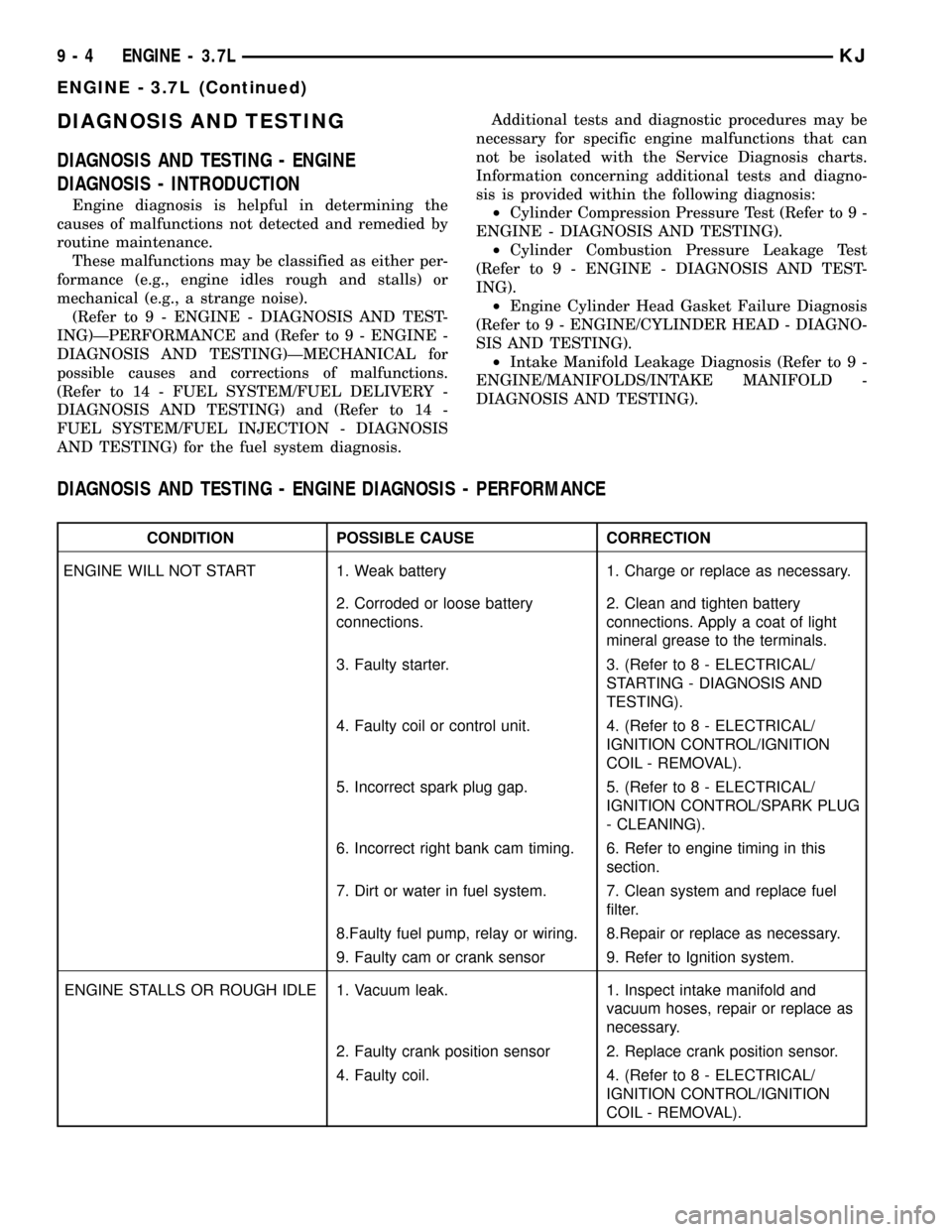
DIAGNOSIS AND TESTING - ENGINE DIAGNOSIS - PERFORMANCE
CONDITION POSSIBLE CAUSE CORRECTION
ENGINE WILL NOT START 1. Weak battery 1. Charge or replace as necessary.
2. Corroded or loose battery
connections.2. Clean and tighten battery
connections. Apply a coat of light
mineral grease to the terminals.
3. Faulty starter. 3. (Refer to 8 - ELECTRICAL/
STARTING - DIAGNOSIS AND
TESTING).
4. Faulty coil or control unit. 4. (Refer to 8 - ELECTRICAL/
IGNITION CONTROL/IGNITION
COIL - REMOVAL).
5. Incorrect spark plug gap. 5. (Refer to 8 - ELECTRICAL/
IGNITION CONTROL/SPARK PLUG
- CLEANING).
6. Incorrect right bank cam timing. 6. Refer to engine timing in this
section.
7. Dirt or water in fuel system. 7. Clean system and replace fuel
filter.
8.Faulty fuel pump, relay or wiring. 8.Repair or replace as necessary.
9. Faulty cam or crank sensor 9. Refer to Ignition system.
ENGINE STALLS OR ROUGH IDLE 1. Vacuum leak. 1. Inspect intake manifold and
vacuum hoses, repair or replace as
necessary.
2. Faulty crank position sensor 2. Replace crank position sensor.
4. Faulty coil. 4. (Refer to 8 - ELECTRICAL/
IGNITION CONTROL/IGNITION
COIL - REMOVAL).
9 - 4 ENGINE - 3.7LKJ
ENGINE - 3.7L (Continued)
Page 1222 of 1803
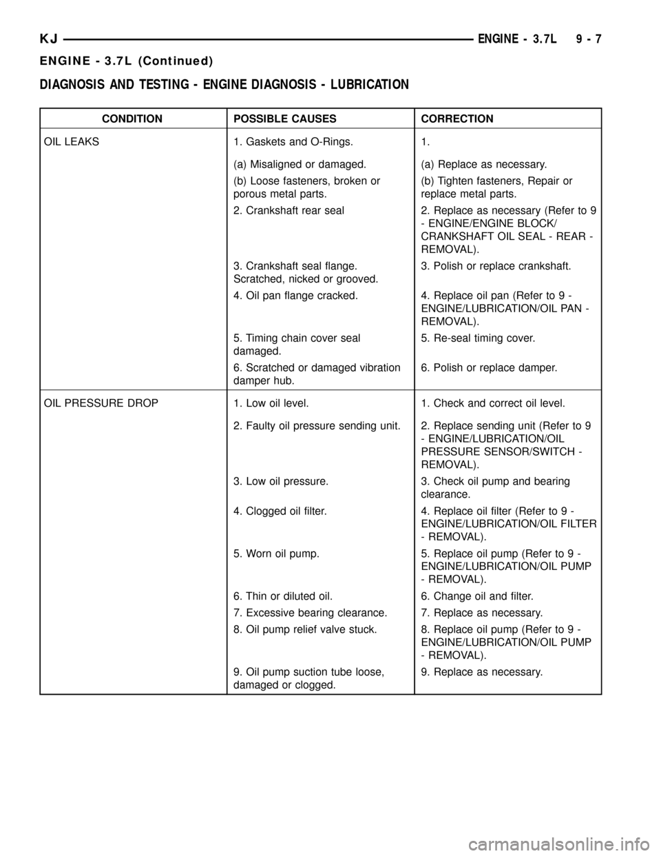
DIAGNOSIS AND TESTING - ENGINE DIAGNOSIS - LUBRICATION
CONDITION POSSIBLE CAUSES CORRECTION
OIL LEAKS 1. Gaskets and O-Rings. 1.
(a) Misaligned or damaged. (a) Replace as necessary.
(b) Loose fasteners, broken or
porous metal parts.(b) Tighten fasteners, Repair or
replace metal parts.
2. Crankshaft rear seal 2. Replace as necessary (Refer to 9
- ENGINE/ENGINE BLOCK/
CRANKSHAFT OIL SEAL - REAR -
REMOVAL).
3. Crankshaft seal flange.
Scratched, nicked or grooved.3. Polish or replace crankshaft.
4. Oil pan flange cracked. 4. Replace oil pan (Refer to 9 -
ENGINE/LUBRICATION/OIL PAN -
REMOVAL).
5. Timing chain cover seal
damaged.5. Re-seal timing cover.
6. Scratched or damaged vibration
damper hub.6. Polish or replace damper.
OIL PRESSURE DROP 1. Low oil level. 1. Check and correct oil level.
2. Faulty oil pressure sending unit. 2. Replace sending unit (Refer to 9
- ENGINE/LUBRICATION/OIL
PRESSURE SENSOR/SWITCH -
REMOVAL).
3. Low oil pressure. 3. Check oil pump and bearing
clearance.
4. Clogged oil filter. 4. Replace oil filter (Refer to 9 -
ENGINE/LUBRICATION/OIL FILTER
- REMOVAL).
5. Worn oil pump. 5. Replace oil pump (Refer to 9 -
ENGINE/LUBRICATION/OIL PUMP
- REMOVAL).
6. Thin or diluted oil. 6. Change oil and filter.
7. Excessive bearing clearance. 7. Replace as necessary.
8. Oil pump relief valve stuck. 8. Replace oil pump (Refer to 9 -
ENGINE/LUBRICATION/OIL PUMP
- REMOVAL).
9. Oil pump suction tube loose,
damaged or clogged.9. Replace as necessary.
KJENGINE - 3.7L 9 - 7
ENGINE - 3.7L (Continued)
Page 1225 of 1803
²Tapping the hole with a special Heli-Coil Tap, or
equivalent.
²Installing an insert into the tapped hole to bring
the hole back to its original thread size.
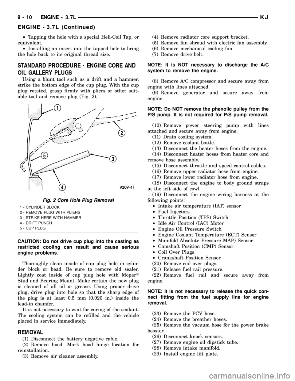
STANDARD PROCEDURE - ENGINE CORE AND
OIL GALLERY PLUGS
Using a blunt tool such as a drift and a hammer,
strike the bottom edge of the cup plug. With the cup
plug rotated, grasp firmly with pliers or other suit-
able tool and remove plug (Fig. 2).
CAUTION: Do not drive cup plug into the casting as
restricted cooling can result and cause serious
engine problems.
Thoroughly clean inside of cup plug hole in cylin-
der block or head. Be sure to remove old sealer.
Lightly coat inside of cup plug hole with Mopart
Stud and Bearing Mount. Make certain the new plug
is cleaned of all oil or grease. Using proper drive
plug, drive plug into hole so that the sharp edge of
the plug is at least 0.5 mm (0.020 in.) inside the
lead-in chamfer.
It is not necessary to wait for curing of the sealant.
The cooling system can be refilled and the vehicle
placed in service immediately.
REMOVAL
(1) Disconnect the battery negative cable.
(2) Remove hood. Mark hood hinge location for
reinstallation.
(3) Remove air cleaner assembly.(4) Remove radiator core support bracket.
(5) Remove fan shroud with electric fan assembly.
(6) Remove mechanical cooling fan.
(7) Remove drive belt.
NOTE: It is NOT necessary to discharge the A/C
system to remove the engine.
(8) Remove A/C compressor and secure away from
engine with lines attached.
(9) Remove generator and secure away from
engine.
NOTE: Do NOT remove the phenolic pulley from the
P/S pump. It is not required for P/S pump removal.
(10) Remove power steering pump with lines
attached and secure away from engine.
(11) Drain cooling system.
(12) Remove coolant bottle.
(13) Disconnect the heater hoses from the engine.
(14) Disconnect heater hoses from heater core and
remove hose assembly.
(15) Disconnect throttle and speed control cables.
(16) Remove upper radiator hose from engine.
(17) Remove lower radiator hose from engine.
(18) Disconnect the engine to body ground straps
at the left side of cowl.
(19) Disconnect the engine wiring harness at the
following points:
²Intake air temperature (IAT) sensor
²Fuel Injectors
²Throttle Position (TPS) Switch
²Idle Air Control (IAC) Motor
²Engine Oil Pressure Switch
²Engine Coolant Temperature (ECT) Sensor
²Manifold Absolute Pressure MAP) Sensor
²Camshaft Position (CMP) Sensor
²Coil Over Plugs
²Crankshaft Position Sensor
(20) Remove coil over plugs.
(21) Release fuel rail pressure.
(22) Remove fuel rail and secure away from
engine.
NOTE: It is not necessary to release the quick con-
nect fitting from the fuel supply line for engine
removal.
(23) Remove the PCV hose.
(24) Remove the breather hoses.
(25) Remove the vacuum hose for the power brake
booster.
(26) Disconnect knock sensors.
(27) Remove engine oil dipstick tube.
(28) Remove intake manifold.
(29) Install engine lift plate.
Fig. 2 Core Hole Plug Removal
1 - CYLINDER BLOCK
2 - REMOVE PLUG WITH PLIERS
3 - STRIKE HERE WITH HAMMER
4 - DRIFT PUNCH
5 - CUP PLUG
9 - 10 ENGINE - 3.7LKJ
ENGINE - 3.7L (Continued)
Page 1226 of 1803
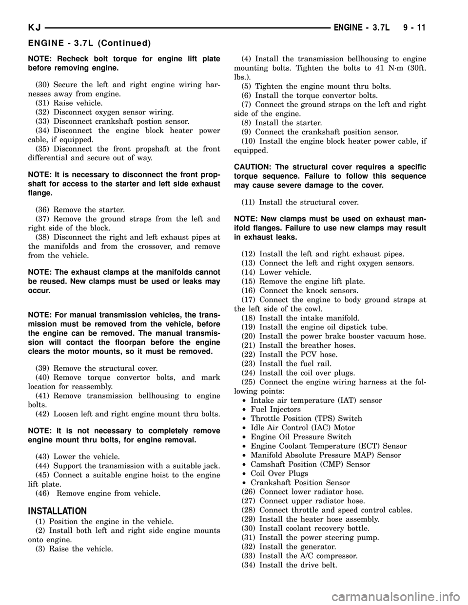
NOTE: Recheck bolt torque for engine lift plate
before removing engine.
(30) Secure the left and right engine wiring har-
nesses away from engine.
(31) Raise vehicle.
(32) Disconnect oxygen sensor wiring.
(33) Disconnect crankshaft postion sensor.
(34) Disconnect the engine block heater power
cable, if equipped.
(35) Disconnect the front propshaft at the front
differential and secure out of way.
NOTE: It is necessary to disconnect the front prop-
shaft for access to the starter and left side exhaust
flange.
(36) Remove the starter.
(37) Remove the ground straps from the left and
right side of the block.
(38) Disconnect the right and left exhaust pipes at
the manifolds and from the crossover, and remove
from the vehicle.
NOTE: The exhaust clamps at the manifolds cannot
be reused. New clamps must be used or leaks may
occur.
NOTE: For manual transmission vehicles, the trans-
mission must be removed from the vehicle, before
the engine can be removed. The manual transmis-
sion will contact the floorpan before the engine
clears the motor mounts, so it must be removed.
(39) Remove the structural cover.
(40) Remove torque convertor bolts, and mark
location for reassembly.
(41) Remove transmission bellhousing to engine
bolts.
(42) Loosen left and right engine mount thru bolts.
NOTE: It is not necessary to completely remove
engine mount thru bolts, for engine removal.
(43) Lower the vehicle.
(44) Support the transmission with a suitable jack.
(45) Connect a suitable engine hoist to the engine
lift plate.
(46) Remove engine from vehicle.
INSTALLATION
(1) Position the engine in the vehicle.
(2) Install both left and right side engine mounts
onto engine.
(3) Raise the vehicle.(4) Install the transmission bellhousing to engine
mounting bolts. Tighten the bolts to 41 N´m (30ft.
lbs.).
(5) Tighten the engine mount thru bolts.
(6) Install the torque convertor bolts.
(7) Connect the ground straps on the left and right
side of the engine.
(8) Install the starter.
(9) Connect the crankshaft position sensor.
(10) Install the engine block heater power cable, if
equipped.
CAUTION: The structural cover requires a specific
torque sequence. Failure to follow this sequence
may cause severe damage to the cover.
(11) Install the structural cover.
NOTE: New clamps must be used on exhaust man-
ifold flanges. Failure to use new clamps may result
in exhaust leaks.
(12) Install the left and right exhaust pipes.
(13) Connect the left and right oxygen sensors.
(14) Lower vehicle.
(15) Remove the engine lift plate.
(16) Connect the knock sensors.
(17) Connect the engine to body ground straps at
the left side of the cowl.
(18) Install the intake manifold.
(19) Install the engine oil dipstick tube.
(20) Install the power brake booster vacuum hose.
(21) Install the breather hoses.
(22) Install the PCV hose.
(23) Install the fuel rail.
(24) Install the coil over plugs.
(25) Connect the engine wiring harness at the fol-
lowing points:
²Intake air temperature (IAT) sensor
²Fuel Injectors
²Throttle Position (TPS) Switch
²Idle Air Control (IAC) Motor
²Engine Oil Pressure Switch
²Engine Coolant Temperature (ECT) Sensor
²Manifold Absolute Pressure MAP) Sensor
²Camshaft Position (CMP) Sensor
²Coil Over Plugs
²Crankshaft Position Sensor
(26) Connect lower radiator hose.
(27) Connect upper radiator hose.
(28) Connect throttle and speed control cables.
(29) Install the heater hose assembly.
(30) Install coolant recovery bottle.
(31) Install the power steering pump.
(32) Install the generator.
(33) Install the A/C compressor.
(34) Install the drive belt.
KJENGINE - 3.7L 9 - 11
ENGINE - 3.7L (Continued)
Page 1246 of 1803
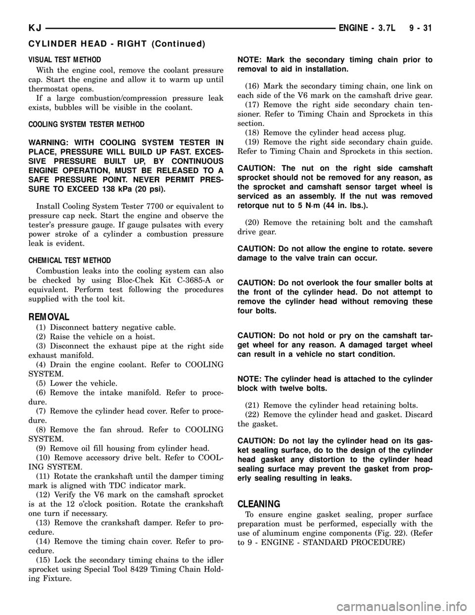
VISUAL TEST METHOD
With the engine cool, remove the coolant pressure
cap. Start the engine and allow it to warm up until
thermostat opens.
If a large combustion/compression pressure leak
exists, bubbles will be visible in the coolant.
COOLING SYSTEM TESTER METHOD
WARNING: WITH COOLING SYSTEM TESTER IN
PLACE, PRESSURE WILL BUILD UP FAST. EXCES-
SIVE PRESSURE BUILT UP, BY CONTINUOUS
ENGINE OPERATION, MUST BE RELEASED TO A
SAFE PRESSURE POINT. NEVER PERMIT PRES-
SURE TO EXCEED 138 kPa (20 psi).
Install Cooling System Tester 7700 or equivalent to
pressure cap neck. Start the engine and observe the
tester's pressure gauge. If gauge pulsates with every
power stroke of a cylinder a combustion pressure
leak is evident.
CHEMICAL TEST METHOD
Combustion leaks into the cooling system can also
be checked by using Bloc-Chek Kit C-3685-A or
equivalent. Perform test following the procedures
supplied with the tool kit.
REMOVAL
(1) Disconnect battery negative cable.
(2) Raise the vehicle on a hoist.
(3) Disconnect the exhaust pipe at the right side
exhaust manifold.
(4) Drain the engine coolant. Refer to COOLING
SYSTEM.
(5) Lower the vehicle.
(6) Remove the intake manifold. Refer to proce-
dure.
(7) Remove the cylinder head cover. Refer to proce-
dure.
(8) Remove the fan shroud. Refer to COOLING
SYSTEM.
(9) Remove oil fill housing from cylinder head.
(10) Remove accessory drive belt. Refer to COOL-
ING SYSTEM.
(11) Rotate the crankshaft until the damper timing
mark is aligned with TDC indicator mark.
(12) Verify the V6 mark on the camshaft sprocket
is at the 12 o'clock position. Rotate the crankshaft
one turn if necessary.
(13) Remove the crankshaft damper. Refer to pro-
cedure.
(14) Remove the timing chain cover. Refer to pro-
cedure.
(15) Lock the secondary timing chains to the idler
sprocket using Special Tool 8429 Timing Chain Hold-
ing Fixture.NOTE: Mark the secondary timing chain prior to
removal to aid in installation.
(16) Mark the secondary timing chain, one link on
each side of the V6 mark on the camshaft drive gear.
(17) Remove the right side secondary chain ten-
sioner. Refer to Timing Chain and Sprockets in this
section.
(18) Remove the cylinder head access plug.
(19) Remove the right side secondary chain guide.
Refer to Timing Chain and Sprockets in this section.
CAUTION: The nut on the right side camshaft
sprocket should not be removed for any reason, as
the sprocket and camshaft sensor target wheel is
serviced as an assembly. If the nut was removed
retorque nut to 5 N´m (44 in. lbs.).
(20) Remove the retaining bolt and the camshaft
drive gear.
CAUTION: Do not allow the engine to rotate. severe
damage to the valve train can occur.
CAUTION: Do not overlook the four smaller bolts at
the front of the cylinder head. Do not attempt to
remove the cylinder head without removing these
four bolts.
CAUTION: Do not hold or pry on the camshaft tar-
get wheel for any reason. A damaged target wheel
can result in a vehicle no start condition.
NOTE: The cylinder head is attached to the cylinder
block with twelve bolts.
(21) Remove the cylinder head retaining bolts.
(22) Remove the cylinder head and gasket. Discard
the gasket.
CAUTION: Do not lay the cylinder head on its gas-
ket sealing surface, do to the design of the cylinder
head gasket any distortion to the cylinder head
sealing surface may prevent the gasket from prop-
erly sealing resulting in leaks.
CLEANING
To ensure engine gasket sealing, proper surface
preparation must be performed, especially with the
use of aluminum engine components (Fig. 22). (Refer
to 9 - ENGINE - STANDARD PROCEDURE)
KJENGINE - 3.7L 9 - 31
CYLINDER HEAD - RIGHT (Continued)