2002 JEEP LIBERTY wire
[x] Cancel search: wirePage 753 of 1803

CIRCUIT FUNCTION
U OPEN
V SPEED CONTROL, WIPER/
WASHER
W OPEN
X AUDIO SYSTEMS
Y OPEN
Z GROUNDS
DESCRIPTION - SECTION IDENTIFICATION AND
INFORMATION
The wiring diagrams are grouped into individual
sections. If a component is most likely found in a par-
ticular group, it will be shown complete (all wires,
connectors, and pins) within that group. For exam-
ple, the Auto Shutdown Relay is most likely to be
found in Group 30, so it is shown there complete. It
can, however, be shown partially in another group if
it contains some associated wiring.
Splice diagrams in Section 8W-70 show the entire
splice and provide references to other sections the
splices serves. Section 8W-70 only contains splice dia-
grams that are not shown in their entirety some-
where else in the wiring diagrams.
Section 8W-80 shows each connector and the cir-
cuits involved with that connector. The connectors
are identified using the name/number on the dia-
gram pages.
WIRING SECTION CHART
GROUP TOPIC
8Wa-01 thru
8W-09General information and Diagram
Overview
8Wa-10 thru
8W-19Main Sources of Power and
Vehicle Grounding
8Wa-20 thru
8W-29Starting and Charging
8Wa-30 thru
8W-39Powertrain/Drivetrain Systems
8Wa-40 thru
8W-49Body Electrical items and A/C
8Wa-50 thru
8W-59Exterior Lighting, Wipers and
Trailer Tow
8Wa-60 thru
8W-69Power Accessories
8Wa-70 Splice Information
8Wa-80 Connector Pin Outs
8Wa-91 Connector, Ground and Splice
Locations
DESCRIPTION - CONNECTOR, GROUND AND
SPLICE INFORMATION
CAUTION: Not all connectors are serviced. Some
connectors are serviced only with a harness. A typ-
ical example might be the Supplemental Restraint
System connectors. Always check parts availability
before attempting a repair.
IDENTIFICATION
In-line connectors are identified by a number, as
follows:
²In-line connectors located in the engine compart-
ment are C100 series numbers
²In-line connectors located in the Instrument
Panel area are C200 series numbers.
²In-line connectors located in the body are C300
series numbers.
²Jumper harness connectors are C400 series
numbers.
²Grounds and ground connectors are identified
with a ªGº and follow the same series numbering as
the in-line connectors.
²Splices are identified with an ªSº and follow the
same series numbering as the in-line connectors.
²Component connectors are identified by the com-
ponent name instead of a number. Multiple connec-
tors on a component use a C1, C2, etc. identifier.
LOCATIONS
Section 8W-91 contains connector/ground/splice
location illustrations. The illustrations contain the
connector name (or number)/ground number/splice
number and component identification. Connector/
ground/splice location charts in section 8W-91 refer-
ence the figure numbers of the illustrations.
The abbreviation T/O is used in the component
location section to indicate a point in which the wir-
ing harness branches out to a component. The abbre-
viation N/S means Not Shown in the illustrations
WARNINGS - GENERAL
WARNINGSprovide information to prevent per-
sonal injury and vehicle damage. Below is a list of
general warnings that should be followed any time a
vehicle is being serviced.
WARNING:: ALWAYS WEAR SAFETY GLASSES FOR
EYE PROTECTION.
WARNING: USE SAFETY STANDS ANYTIME A PRO-
CEDURE REQUIRES BEING UNDER A VEHICLE.
8Wa - 01 - 6 8W-01 WIRING DIAGRAM INFORMATIONKJ
WIRING DIAGRAM INFORMATION (Continued)
Page 754 of 1803

WARNING: BE SURE THAT THE IGNITION SWITCH
ALWAYS IS IN THE OFF POSITION, UNLESS THE
PROCEDURE REQUIRES IT TO BE ON.
WARNING: SET THE PARKING BRAKE WHEN
WORKING ON ANY VEHICLE. AN AUTOMATIC
TRANSMISSION SHOULD BE IN PARK. A MANUAL
TRANSMISSION SHOULD BE IN NEUTRAL.
WARNING: OPERATE THE ENGINE ONLY IN A
WELL-VENTILATED AREA.
WARNING: KEEP AWAY FROM MOVING PARTS
WHEN THE ENGINE IS RUNNING, ESPECIALLY THE
FAN AND BELTS.
WARNING: TO PREVENT SERIOUS BURNS, AVOID
CONTACT WITH HOT PARTS SUCH AS THE RADIA-
TOR, EXHAUST MANIFOLD(S), TAIL PIPE, CATA-
LYTIC CONVERTER AND MUFFLER.
WARNING: DO NOT ALLOW FLAME OR SPARKS
NEAR THE BATTERY. GASES ARE ALWAYS
PRESENT IN AND AROUND THE BATTERY.
WARNING: ALWAYS REMOVE RINGS, WATCHES,
LOOSE HANGING JEWELRY AND AVOID LOOSE
CLOTHING.
DIAGNOSIS AND TESTING - WIRING HARNESS
TROUBLESHOOTING TOOLS
When diagnosing a problem in an electrical circuit
there are several common tools necessary. These tools
are listed and explained below.
²Jumper Wire - This is a test wire used to con-
nect two points of a circuit. It can be used to bypass
an open in a circuit.
WARNING: NEVER USE A JUMPER WIRE ACROSS
A LOAD, SUCH AS A MOTOR, CONNECTED
BETWEEN A BATTERY FEED AND GROUND.
²Voltmeter - Used to check for voltage on a cir-
cuit. Always connect the black lead to a known good
ground and the red lead to the positive side of the
circuit.
CAUTION: Most of the electrical components used
in today's vehicles are Solid State. When checking
voltages in these circuits, use a meter with a 10 -
megohm or greater impedance rating.²Ohmmeter - Used to check the resistance
between two points of a circuit. Low or no resistance
in a circuit means good continuity.
CAUTION: Most of the electrical components used
in today's vehicles are Solid State. When checking
resistance in these circuits use a meter with a 10 -
megohm or greater impedance rating. In addition,
make sure the power is disconnected from the cir-
cuit. Circuits that are powered up by the vehicle's
electrical system can cause damage to the equip-
ment and provide false readings.
²Probing Tools - These tools are used for probing
terminals in connectors (Fig. 5). Select the proper
size tool from Special Tool Package 6807, and insert
it into the terminal being tested. Use the other end
of the tool to insert the meter probe.
INTERMITTENT AND POOR CONNECTIONS
Most intermittent electrical problems are caused
by faulty electrical connections or wiring. It is also
possible for a sticking component or relay to cause a
problem. Before condemning a component or wiring
assembly, check the following items.
²Connectors are fully seated
²Spread terminals, or terminal push out
²Terminals in the wiring assembly are fully
seated into the connector/component and locked into
position
²Dirt or corrosion on the terminals. Any amount
of corrosion or dirt could cause an intermittent prob-
lem
²Damaged connector/component casing exposing
the item to dirt or moisture
²Wire insulation that has rubbed through causing
a short to ground
²Some or all of the wiring strands broken inside
of the insulation
²Wiring broken inside of the insulation
Fig. 5 PROBING TOOL
1 - SPECIAL TOOL 6801
2 - PROBING END
KJ8W-01 WIRING DIAGRAM INFORMATION8Wa-01-7
WIRING DIAGRAM INFORMATION (Continued)
Page 757 of 1803

SPECIAL TOOLS
WIRING/TERMINAL
CONNECTOR
REMOVAL
(1) Disconnect battery.
(2) Release Connector Lock (Fig. 10).
(3) Disconnect the connector being repaired from
its mating half/component.
(4) Remove the dress cover (if applicable) (Fig. 10).
(5) Release the Secondary Terminal Lock, if
required (Fig. 11).
(6) Position the connector locking finger away from
the terminal using the proper special tool. Pull on
the wire to remove the terminal from the connector
(Fig. 12).
PROBING TOOL PACKAGE 6807
TERMINAL PICK TOOL SET 6680
TERMINAL REMOVING TOOLS 6932 AND 8638
TERMINAL REMOVING TOOL 6934
Fig. 10 REMOVAL OF DRESS COVER
1 - DRESS COVER
2 - CONNECTOR LOCK
3 - CONNECTOR
8Wa - 01 - 10 8W-01 WIRING DIAGRAM INFORMATIONKJ
WIRING DIAGRAM INFORMATION (Continued)
Page 760 of 1803

INSTALLATION
(1) Insert the removed terminal in the same cavity
on the repair connector.
(2) Repeat steps for each terminal in the connec-
tor, being sure that all wires are inserted into the
proper cavities. For additional connector pin-out
identification, refer to the wiring diagrams.
(3) When the connector is re-assembled, the sec-
ondary terminal lock must be placed in the locked
position to prevent terminal push out.
(4) Replace dress cover (if applicable).
(5) Connect connector to its mating half/compo-
nent.
(6) Connect battery and test all affected systems.
DIODE
REMOVAL
(1) Disconnect the battery.
(2) Locate the diode in the harness, and remove
the protective covering.
(3) Remove the diode from the harness, pay atten-
tion to the current flow direction (Fig. 13).
INSTALLATION
(1) Remove the insulation from the wires in the
harness. Only remove enough insulation to solder in
the new diode.(2) Install the new diode in the harness, making
sure current flow is correct. If necessary, refer to the
appropriate wiring diagram for current flow (Fig. 13).
(3) Solder the connection together using rosin core
type solder only.Do not use acid core solder.
(4) Tape the diode to the harness using electrical
tape. Make sure the diode is completely sealed from
the elements.
(5) Re-connect the battery and test affected sys-
tems.
TERMINAL
REMOVAL
(1) Follow steps for removing terminals described
in the connector removal section.
(2) Cut the wire 6 inches from the back of the con-
nector.
INSTALLATION
(1) Select a wire from the terminal repair kit that
best matches the color and gage of the wire being
repaired.
(2) Cut the repair wire to the proper length and
remove one±half (1/2) inch of insulation.
(3) Splice the repair wire to the wire harness (see
wire splicing procedure).
(4) Insert the repaired wire into the connector.
(5) Install the connector locking wedge, if required,
and reconnect the connector to its mating half/compo-
nent.
(6) Re-tape the wire harness starting at 1±1/2
inches behind the connector and 2 inches past the
repair.
(7) Connect battery and test all affected systems.
WIRE
STANDARD PROCEDURE - WIRE SPLICING
When splicing a wire, it is important that the cor-
rect gage be used as shown in the wiring diagrams.
(1) Remove one-half (1/2) inch of insulation from
each wire that needs to be spliced.
(2) Place a piece of adhesive lined heat shrink tub-
ing on one side of the wire. Make sure the tubing will
be long enough to cover and seal the entire repair
area.
Fig. 13 DIODE IDENTIFICATION
1 - CURRENT FLOW
2 - BAND AROUND DIODE INDICATES CURRENT FLOW
3 - DIODE AS SHOWN IN THE DIAGRAMS
KJ8W-01 WIRING DIAGRAM INFORMATION8Wa-01-13
CONNECTOR (Continued)
Page 761 of 1803

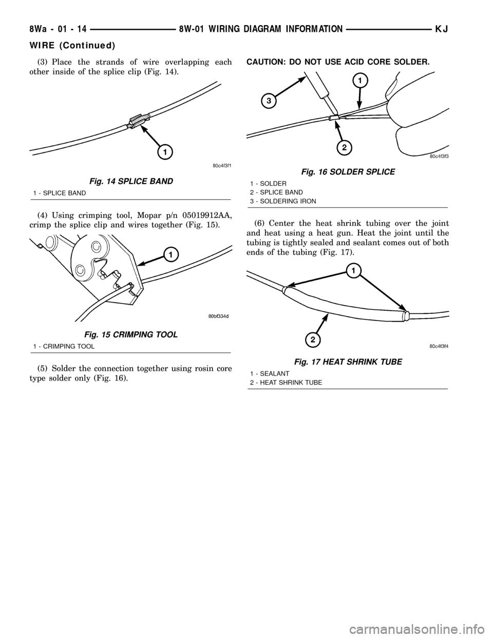
(3) Place the strands of wire overlapping each
other inside of the splice clip (Fig. 14).
(4) Using crimping tool, Mopar p/n 05019912AA,
crimp the splice clip and wires together (Fig. 15).
(5) Solder the connection together using rosin core
type solder only (Fig. 16).CAUTION: DO NOT USE ACID CORE SOLDER.
(6) Center the heat shrink tubing over the joint
and heat using a heat gun. Heat the joint until the
tubing is tightly sealed and sealant comes out of both
ends of the tubing (Fig. 17).
Fig. 14 SPLICE BAND
1 - SPLICE BAND
Fig. 15 CRIMPING TOOL
1 - CRIMPING TOOL
Fig. 16 SOLDER SPLICE
1 - SOLDER
2 - SPLICE BAND
3 - SOLDERING IRON
Fig. 17 HEAT SHRINK TUBE
1 - SEALANT
2 - HEAT SHRINK TUBE
8Wa - 01 - 14 8W-01 WIRING DIAGRAM INFORMATIONKJ
WIRE (Continued)
Page 1224 of 1803

CYLINDER COMBUSTION PRESSURE LEAKAGE DIAGNOSIS CHART
CONDITION POSSIBLE CAUSE CORRECTION
AIR ESCAPES THROUGH
THROTTLE BODYIntake valve bent, burnt, or not
seated properlyInspect valve and valve seat.
Reface or replace, as necessary.
Inspect valve springs. Replace as
necessary.
AIR ESCAPES THROUGH
TAILPIPEExhaust valve bent, burnt, or not
seated properlyInspect valve and valve seat.
Reface or replace, as necessary.
Inspect valve springs. Replace as
necessary.
AIR ESCAPES THROUGH
RADIATORHead gasket leaking or cracked
cylinder head or blockRemove cylinder head and inspect.
Replace defective part
MORE THAN 50% LEAKAGE
FROM ADJACENT CYLINDERSHead gasket leaking or crack in
cylinder head or block between
adjacent cylindersRemove cylinder head and inspect.
Replace gasket, head, or block as
necessary
MORE THAN 25% LEAKAGE AND
AIR ESCAPES THROUGH OIL
FILLER CAP OPENING ONLYStuck or broken piston rings;
cracked piston; worn rings and/or
cylinder wallInspect for broken rings or piston.
Measure ring gap and cylinder
diameter, taper and out-of-round.
Replace defective part as necessary
STANDARD PROCEDURE
STANDARD PROCEDURE - ENGINE GASKET
SURFACE PREPARATION
To ensure engine gasket sealing, proper surface
preparation must be performed, especially with the
use of aluminum engine components and multi-layer
steel cylinder head gaskets.
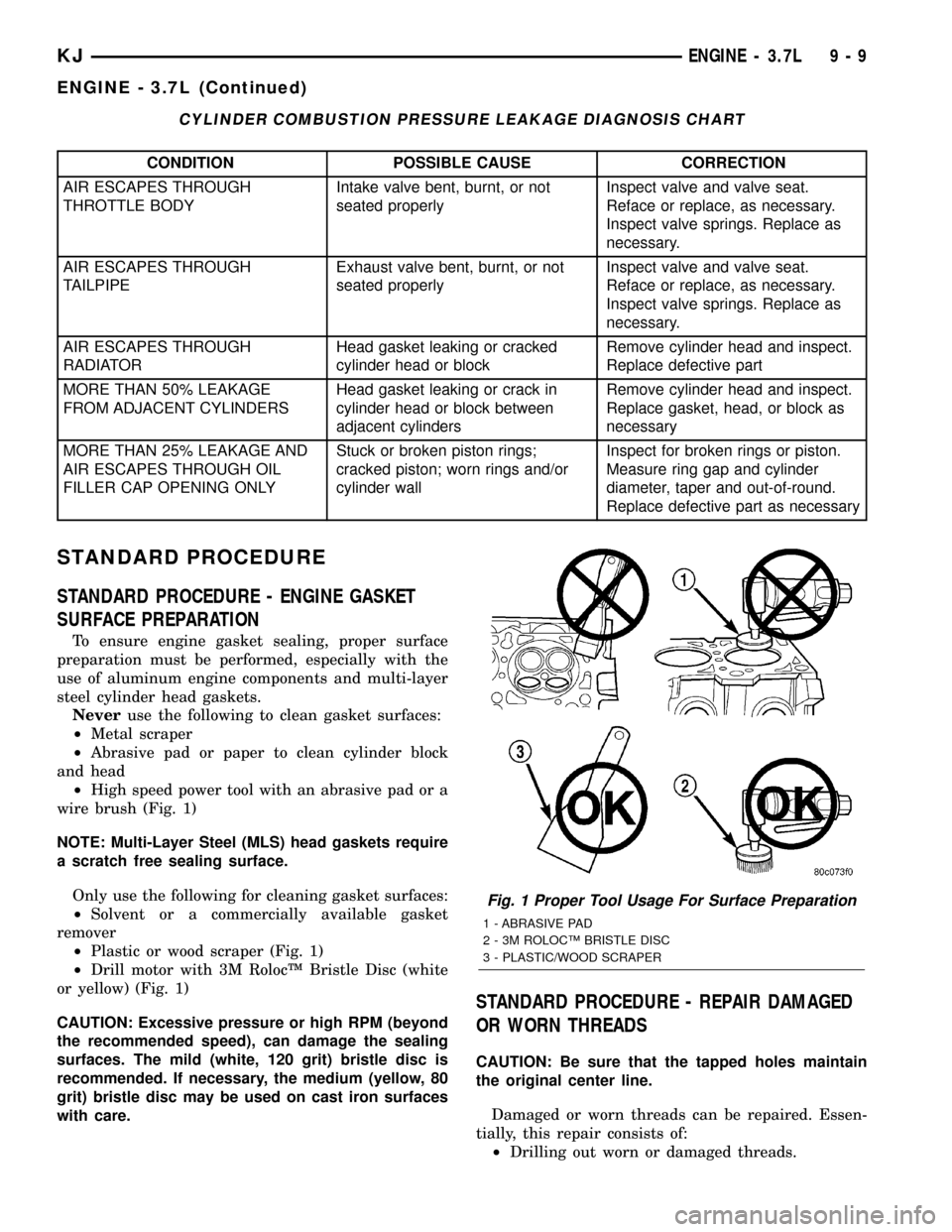
Neveruse the following to clean gasket surfaces:
²Metal scraper
²Abrasive pad or paper to clean cylinder block
and head
²High speed power tool with an abrasive pad or a
wire brush (Fig. 1)
NOTE: Multi-Layer Steel (MLS) head gaskets require
a scratch free sealing surface.
Only use the following for cleaning gasket surfaces:
²Solvent or a commercially available gasket
remover
²Plastic or wood scraper (Fig. 1)
²Drill motor with 3M RolocŸ Bristle Disc (white
or yellow) (Fig. 1)
CAUTION: Excessive pressure or high RPM (beyond
the recommended speed), can damage the sealing
surfaces. The mild (white, 120 grit) bristle disc is
recommended. If necessary, the medium (yellow, 80
grit) bristle disc may be used on cast iron surfaces
with care.
STANDARD PROCEDURE - REPAIR DAMAGED
OR WORN THREADS
CAUTION: Be sure that the tapped holes maintain
the original center line.
Damaged or worn threads can be repaired. Essen-
tially, this repair consists of:
²Drilling out worn or damaged threads.
Fig. 1 Proper Tool Usage For Surface Preparation
1 - ABRASIVE PAD
2 - 3M ROLOCŸ BRISTLE DISC
3 - PLASTIC/WOOD SCRAPER
KJENGINE - 3.7L 9 - 9
ENGINE - 3.7L (Continued)
Page 1229 of 1803

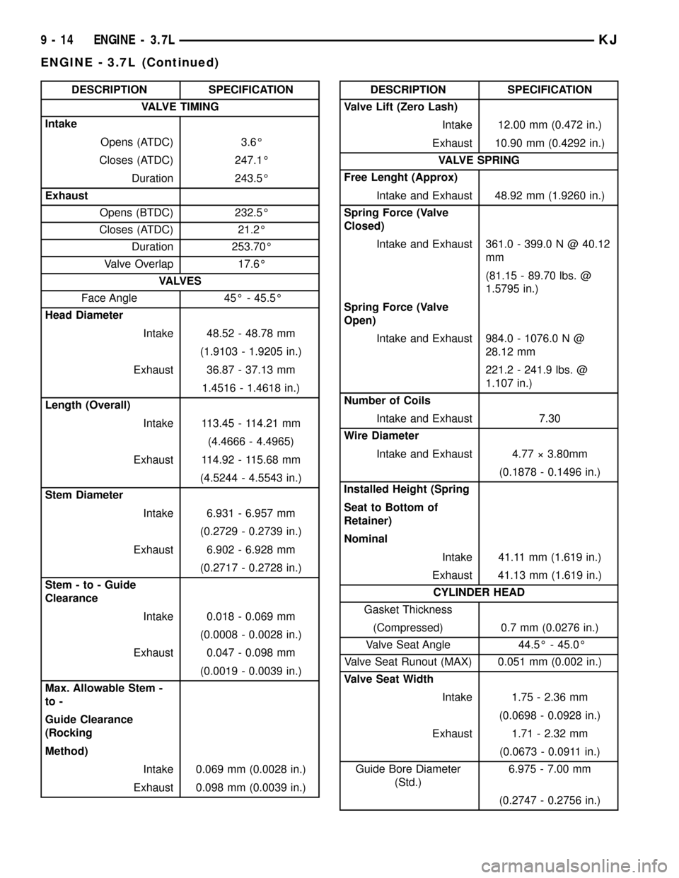
DESCRIPTION SPECIFICATION
VALVE TIMING
Intake
Opens (ATDC) 3.6É
Closes (ATDC) 247.1É
Duration 243.5É
Exhaust
Opens (BTDC) 232.5É
Closes (ATDC) 21.2É
Duration 253.70É
Valve Overlap 17.6É
VA LV E S
Face Angle 45É - 45.5É
Head Diameter
Intake 48.52 - 48.78 mm
(1.9103 - 1.9205 in.)
Exhaust 36.87 - 37.13 mm
1.4516 - 1.4618 in.)
Length (Overall)
Intake 113.45 - 114.21 mm
(4.4666 - 4.4965)
Exhaust 114.92 - 115.68 mm
(4.5244 - 4.5543 in.)
Stem Diameter
Intake 6.931 - 6.957 mm
(0.2729 - 0.2739 in.)
Exhaust 6.902 - 6.928 mm
(0.2717 - 0.2728 in.)
Stem - to - Guide
Clearance
Intake 0.018 - 0.069 mm
(0.0008 - 0.0028 in.)
Exhaust 0.047 - 0.098 mm
(0.0019 - 0.0039 in.)
Max. Allowable Stem -
to -
Guide Clearance
(Rocking
Method)
Intake 0.069 mm (0.0028 in.)
Exhaust 0.098 mm (0.0039 in.)DESCRIPTION SPECIFICATION
Valve Lift (Zero Lash)
Intake 12.00 mm (0.472 in.)
Exhaust 10.90 mm (0.4292 in.)
VALVE SPRING
Free Lenght (Approx)
Intake and Exhaust 48.92 mm (1.9260 in.)
Spring Force (Valve
Closed)
Intake and Exhaust 361.0 - 399.0 N @ 40.12
mm
(81.15 - 89.70 lbs. @
1.5795 in.)
Spring Force (Valve
Open)
Intake and Exhaust 984.0 - 1076.0 N @
28.12 mm
221.2 - 241.9 lbs. @
1.107 in.)
Number of Coils
Intake and Exhaust 7.30
Wire Diameter
Intake and Exhaust 4.77 ý 3.80mm
(0.1878 - 0.1496 in.)
Installed Height (Spring
Seat to Bottom of
Retainer)
Nominal
Intake 41.11 mm (1.619 in.)
Exhaust 41.13 mm (1.619 in.)
CYLINDER HEAD
Gasket Thickness
(Compressed) 0.7 mm (0.0276 in.)
Valve Seat Angle 44.5É - 45.0É
Valve Seat Runout (MAX) 0.051 mm (0.002 in.)
Valve Seat Width
Intake 1.75 - 2.36 mm
(0.0698 - 0.0928 in.)
Exhaust 1.71 - 2.32 mm
(0.0673 - 0.0911 in.)
Guide Bore Diameter
(Std.)6.975 - 7.00 mm
(0.2747 - 0.2756 in.)
9 - 14 ENGINE - 3.7LKJ
ENGINE - 3.7L (Continued)
Page 1266 of 1803

assemblies from the engine, rotate crankshaft so the
each connecting rod is centered in cylinder bore.
CAUTION: DO NOT use a number stamp or a punch
to mark connecting rods or caps, as damage to
connecting rods could occur
NOTE: Connecting rods and bearing caps are not
interchangeable and should be marked before
removing to ensure correct reassembly.
(4) Mark connecting rod and bearing cap positions
using a permanent ink marker or scribe tool.
CAUTION: Care must be taken not to damage the
fractured rod and cap joint face surfaces, as engine
damage may occur.
(5) Remove connecting rod cap. Install Special Tool
8507 Connecting Rod Guides into the connecting rod
being removed. Remove piston from cylinder bore.
Repeat this procedure for each piston being removed.
CAUTION: Care must be taken not to nick crank-
shaft journals, as engine damage may occur
(6) Immediately after piston and connecting rod
removal, install bearing cap on the mating connect-
ing rod to prevent damage to the fractured cap and
rod surfaces.
CLEANING
CAUTION: DO NOT use a wire wheel or other abra-
sive cleaning devise to clean the pistons or con-
necting rods. The pistons have a Moly coating, this
coating must not be damaged.
(1) Using a suitable cleaning solvent clean the pis-
tons in warm water and towel dry.
(2) Use a wood or plastic scraper to clean the ring
land grooves.
CAUTION: DO NOT remove the piston pin from the
piston and connecting rod assembly.
INSPECTION
Check the connecting rod journal for excessive
wear, taper and scoring (Refer to 9 - ENGINE/EN-
GINE BLOCK/CONNECTING ROD BEARINGS -
STANDARD PROCEDURE).
Check the connecting rod for signs of twist or bend-
ing.
Check the piston for taper and elliptical shape
before it is fitted into the cylinder bore (Refer to 9 -
ENGINE/ENGINE BLOCK/PISTON & CONNECT-
ING ROD - STANDARD PROCEDURE).
Check the piston for scoring, or scraping marks in
the piston skirts. Check the ring lands for cracks
and/or deterioration.
INSTALLATION
(1) Before installing piston and connecting rod
assemblies into the bore, install the piston rings.
(2) Immerse the piston head and rings in clean
engine oil. Position a ring compressor over the piston
and rings. Tighten ring compressor.Ensure posi-
tion of rings do not change during this opera-
tion.
(3) Position bearing onto connecting rod. Ensure
that tabs in bearing shell aligns with slots in con-
necting rod. Verify that parting line of bearing is
aligned with parting line of connecting rod.
(4) Lubricate bearing surface with clean engine oil.
(5) Install Special Tool 8507 Connecting Rod
Guides into connecting rod bolt threads (Fig. 55).
(6) The pistons are marked on the piston pin bore
surface with an raised ªFº indicating installation
position. This mark must be pointing toward the
front of engine on both cylinder banks. The connect-
ing rod oil slinger slot faces the front of the engine
(Fig. 56).
(7) Wipe cylinder bore clean and lubricate with
engine oil.
(8) Rotate crankshaft until connecting rod journal
is on the center of cylinder bore. Insert rod and pis-
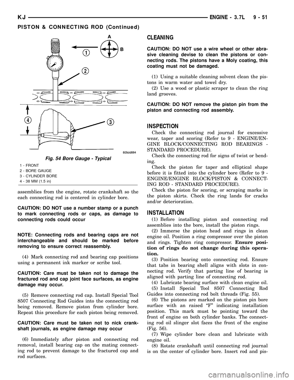
Fig. 54 Bore Gauge - Typical
1 - FRONT
2 - BORE GAUGE
3 - CYLINDER BORE
4 - 38 MM (1.5 in)
KJENGINE - 3.7L 9 - 51
PISTON & CONNECTING ROD (Continued)