2002 JEEP LIBERTY oil
[x] Cancel search: oilPage 96 of 1803

(5) Apply a light coating of gear lubricant on the
lip of pinion seal and intall seal with an appropriate
installer (Fig. 55).
(6) Install rear pinion bearing and oil slinger/depth
shim onto the pinion shaft with Installer 6448 and a
press (Fig. 56).(7) Install anewcollapsible spacer on pinion shaft
and install the pinion into the housing (Fig. 57).
(8) Install pinion companion flange, with Installer
W-162-D, Cup 8109 and Spanner Wrench 6958.
(9) Install pinion anewnut onto the pinion gear
and tighten the nut to 216 N´m (160 ft. lbs.).Do not
over-tighten.
CAUTION: Never loosen pinion gear nut to decrease
pinion rotating torque and never exceed specified
preload torque. If preload torque is exceeded a new
collapsible spacer must be installed.
Fig. 55 PINION SEAL
1 - HANDLE
2 - INSTALLER
Fig. 56 REAR PINION BEARING
1 - INSTALLER
2 - OIL SLINGER
3 - PINION GEAR
4 - REAR PINION BEARING
5 - PRESS
Fig. 57 COLLAPSIBLE PRELOAD SPACER
1 - COLLAPSIBLE SPACER
2 - SHOULDER
3 - PINION GEAR
4 - OIL SLINGER
5 - REAR BEARING
KJFRONT AXLE - 186FIA 3 - 47
PINION GEAR/RING GEAR (Continued)
Page 103 of 1803

REMOVAL
(1) Raise and support the vehicle.
(2) Position a lift/jack under the axle and secure
axle to device.
(3) Remove wheels and tires.
(4) Mark propeller shaft and pinion yoke for
installation reference.
(5) Remove propeller shaft and suspend under the
vehicle.
(6) Remove brake drums, parking brake cables and
speed sensor from the axle.
(7) Disconnect the brake hose at the body junction
block.
(8) Remove brakes and backing plates.
(9) Remove vent hose from the axle shaft tube.
(10) Remove the stabilizer bar (Fig. 5).
(11) Remove upper control arm ball joint pinch
bolt from bracket (Fig. 6).
(12) Remove shock absorbers from axle brackets
(Fig. 7).
(13) Loosen all lower control arms mounting bolts
(Fig. 8).
(14) Lower axle enough to remove coil springs and
spring insulators.
(15) Remove lower control arm bolts from the axle
brackets.
(16) Lower and remove the axle.
INSTALLATION
CAUTION: The weight of the vehicle must be sup-
ported by the springs before the lower control arms
are tightened. This must be done to maintain vehi-
cle ride height and prevent premature bushing fail-
ure.(1) Raise the axle under the vehicle.
(2) Install lower control arms onto the axle brack-
ets and loosely install the mounting bolts.
(3) Install coil spring isolators and spring.
(4) Raise axle up until springs are seated.
(5) Install upper control arm ball joint into axle
bracket and tighten pinch bolt to torque specification.
(6) Install shock absorbers and tighten nuts to
torque specification.
(7) Install stabilizer bar and tighten nuts to torque
specification.
(8) Install brake backing plates, parking brake
cables, brake drums and speed sensor.
(9) Install brake hose to the body junction block
and bleed the brakes.
Fig. 5 STABILIZER BAR MOUNTS
1 - STABILIZER BAR MOUNTING BOLTS
2 - LOWER SUSPENSION ARM
Fig. 6 BALL JOINT PINCH BOLT
1 - UPPER BALL JOINT
2 - PINCH BOLT
Fig. 7 SHOCK ABSORBER
1 - UPPER MOUNTING BOLT
2 - LOWER MOUNTING BOLT
3 - 54 REAR AXLE - 198RBIKJ
REAR AXLE - 198RBI (Continued)
Page 120 of 1803

(6) Using yoke with Spanner Wrench 6958 and a
torque wrench set at 474 N´m (350 ft. lbs.), (Fig. 41)
slowly tighten the nut in 6.8 N´m (5 ft. lbs.) incre-
ments until the rotating torque is achieved. Measure
the rotating torque frequently to avoid over crushing
the collapsible spacer (Fig. 42).
NOTE: If more than 474 N´m (350 ft. lbs.) torque is
required to crush the collapsible spacer, the spacer
is defective and must be replaced.
(7) Check rotating torque with an inch pound
torque wrench (Fig. 42). The rotating torque of the
pinion gear should be, the reading recorded during
removal plus an additional 0.56 N´m (5 in. lbs.).
(8) Install propeller shaft with reference marks
aligned.
(9) Install rear brake drums.
(10) Add gear lubricant, if necessary.
(11) Install wheel and tire assemblies.
(12) Remove supports and lower vehicle.
DIFFERENTIAL
REMOVAL
(1) Raise and support vehicle.
(2) Remove differential cover and drain fluid.
(3) Clean the housing cavity with flushing oil, light
engine oil or lint free cloth.NOTE: Do not use water, steam, kerosene or gaso-
line for cleaning.
(4) Remove axle shafts.
(5)
Note the reference letters stamped on the bearing
caps and housing machined sealing surface (Fig. 43).
Fig. 41 YOKE SPANNER WRENCH
1 - PINION YOKE
2 - WRENCH
3 - PIPE
Fig. 42 PINION ROTATING TORQUE
1 - TORQUE WRENCH
2 - PINION YOKE
Fig. 43 BEARING CAP IDENTIFICATION
1 - REFERENCE LETTERS
2 - REFERENCE LETTERS
KJREAR AXLE - 198RBI 3 - 71
COLLAPSIBLE SPACER (Continued)
Page 130 of 1803

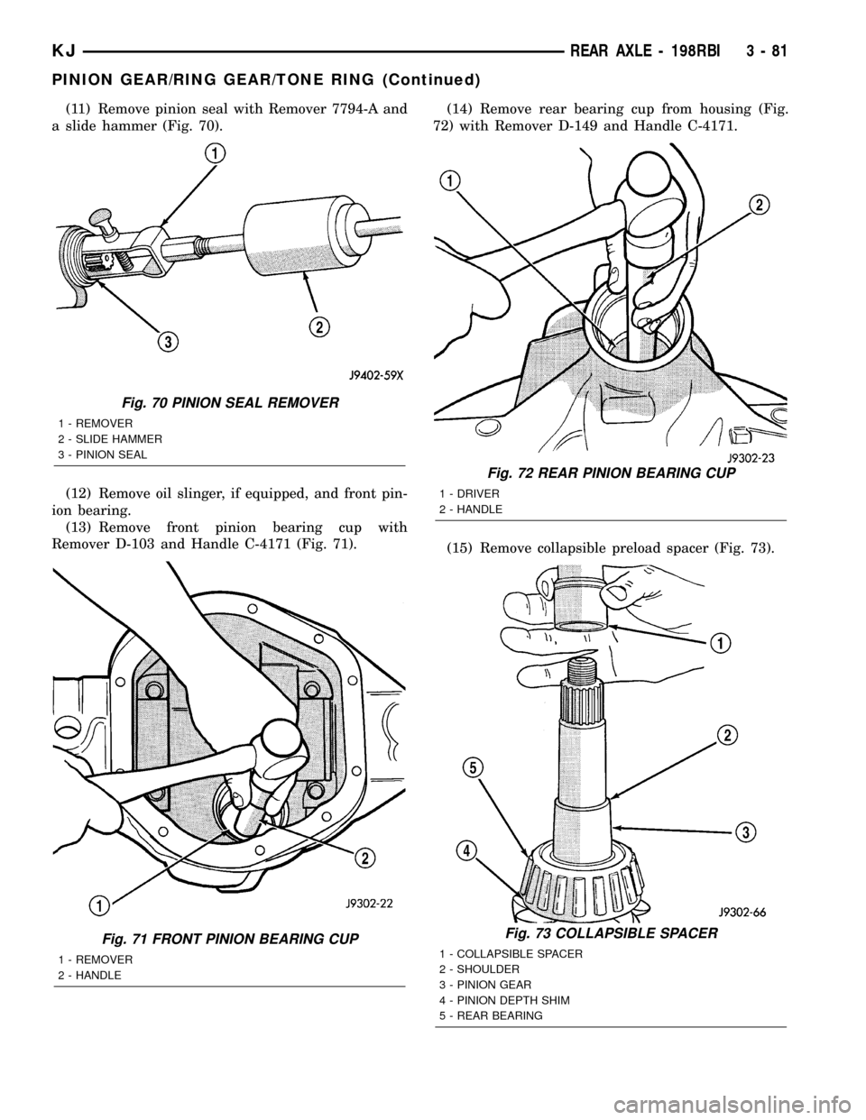
(11) Remove pinion seal with Remover 7794-A and
a slide hammer (Fig. 70).
(12) Remove oil slinger, if equipped, and front pin-
ion bearing.
(13) Remove front pinion bearing cup with
Remover D-103 and Handle C-4171 (Fig. 71).(14) Remove rear bearing cup from housing (Fig.
72) with Remover D-149 and Handle C-4171.
(15) Remove collapsible preload spacer (Fig. 73).
Fig. 70 PINION SEAL REMOVER
1 - REMOVER
2 - SLIDE HAMMER
3 - PINION SEAL
Fig. 71 FRONT PINION BEARING CUP
1 - REMOVER
2 - HANDLE
Fig. 72 REAR PINION BEARING CUP
1 - DRIVER
2 - HANDLE
Fig. 73 COLLAPSIBLE SPACER
1 - COLLAPSIBLE SPACER
2 - SHOULDER
3 - PINION GEAR
4 - PINION DEPTH SHIM
5 - REAR BEARING
KJREAR AXLE - 198RBI 3 - 81
PINION GEAR/RING GEAR/TONE RING (Continued)
Page 131 of 1803

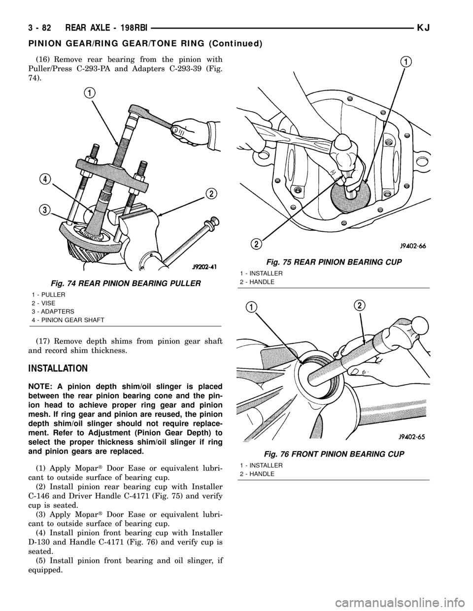
(16) Remove rear bearing from the pinion with
Puller/Press C-293-PA and Adapters C-293-39 (Fig.
74).
(17) Remove depth shims from pinion gear shaft
and record shim thickness.
INSTALLATION
NOTE: A pinion depth shim/oil slinger is placed
between the rear pinion bearing cone and the pin-
ion head to achieve proper ring gear and pinion
mesh. If ring gear and pinion are reused, the pinion
depth shim/oil slinger should not require replace-
ment. Refer to Adjustment (Pinion Gear Depth) to
select the proper thickness shim/oil slinger if ring
and pinion gears are replaced.
(1) Apply MopartDoor Ease or equivalent lubri-
cant to outside surface of bearing cup.
(2) Install pinion rear bearing cup with Installer
C-146 and Driver Handle C-4171 (Fig. 75) and verify
cup is seated.
(3) Apply MopartDoor Ease or equivalent lubri-
cant to outside surface of bearing cup.
(4) Install pinion front bearing cup with Installer
D-130 and Handle C-4171 (Fig. 76) and verify cup is
seated.
(5) Install pinion front bearing and oil slinger, if
equipped.
Fig. 74 REAR PINION BEARING PULLER
1 - PULLER
2 - VISE
3 - ADAPTERS
4 - PINION GEAR SHAFT
Fig. 75 REAR PINION BEARING CUP
1 - INSTALLER
2 - HANDLE
Fig. 76 FRONT PINION BEARING CUP
1 - INSTALLER
2 - HANDLE
3 - 82 REAR AXLE - 198RBIKJ
PINION GEAR/RING GEAR/TONE RING (Continued)
Page 140 of 1803

REMOVAL
(1) Raise and support the vehicle.
(2) Position a lift/jack under the axle and secure
axle to device.
(3) Remove wheels and tires.
(4) Mark propeller shaft and pinion yoke for
installation reference.
(5) Remove propeller shaft and suspend under the
vehicle.
(6) Remove brake drums, parking brake cables and
speed sensor from the axle.
(7) Disconnect the brake hose at the body junction
block.
(8) Remove brakes and backing plates.
(9) Remove vent hose from the axle shaft tube.
(10) Remove the stabilizer bar (Fig. 4).
(11) Remove upper control arm ball joint pinch
bolt from bracket (Fig. 5).
(12) Remove shock absorbers from axle brackets
(Fig. 6).
(13) Loosen all lower control arms mounting bolts
(Fig. 7).
(14) Lower axle enough to remove coil springs and
spring insulators.
(15) Remove lower control arm bolts from the axle
brackets.
(16) Lower and remove the axle.
INSTALLATION
CAUTION: The weight of the vehicle must be sup-
ported by the springs before the lower control arms
are tightened. This must be done to maintain vehi-
cle ride height and prevent premature bushing fail-
ure.(1) Raise the axle under the vehicle.
(2) Install lower control arms onto the axle brack-
ets and loosely install the mounting bolts.
(3) Install coil spring isolators and spring.
(4) Raise axle up until springs are seated.
(5) Install upper control arm ball joint into axle
bracket and tighten pinch bolt to torque specification.
(6) Install shock absorbers and tighten nuts to
torque specification.
(7) Install stabilizer bar and tighten nuts to torque
specification.
(8) Install brake backing plates, parking brake
cables, brake drums and speed sensor.
(9) Install brake hose to the body junction block
and bleed the brakes.
Fig. 4 STABILIZER BAR MOUNTS
1 - STABILIZER BAR MOUNTING BOLTS
2 - LOWER SUSPENSION ARM
Fig. 5 BALL JOINT PINCH BOLT
1 - UPPER BALL JOINT
2 - PINCH BOLT
Fig. 6 SHOCK ABSORBER
1 - UPPER MOUNTING BOLT
2 - LOWER MOUNTING BOLT
KJREAR AXLE - 8 1/4 3 - 91
REAR AXLE - 8 1/4 (Continued)
Page 153 of 1803

lbs.) increments until proper rotating torque is
achieved.
NOTE: The bearing rotating torque should be con-
stant during a complete revolution of the pinion. If
the rotating torque varies, it indicates a binding
condition.
(9) The seal replacement is unacceptable if the
final pinion nut torque is less than 285 N´m (210 ft.
lbs.).
(10) Install the propeller shaft with the installa-
tion reference marks aligned.
(11) Install the brake drums.
(12) Check the differential housing lubricant level.
(13) Install wheel and tire assemblies and lower
the vehicle.
DIFFERENTIAL
REMOVAL
(1) Raise and support vehicle.
(2) Remove fill hole plug from the differential
housing cover.
(3) Remove differential housing cover and drain
housing.
(4) Clean the housing cavity with a flushing oil,
light engine oil or lint free cloth.Do not use water,
steam, kerosene or gasoline for cleaning.(5) Remove the axle shafts.
NOTE: Side play resulting from bearing races being
loose on case hubs requires replacement of the dif-
ferential case.
(6) Mark the differential housing and bearing caps
for installation reference (Fig. 28).
(7) Remove bearing threaded adjuster locks from
each bearing cap.
(8) Loosen bearing cap bolts, them loosen the
threaded adjusters with Wrench C-4164 (Fig. 29).
Fig. 27 Pinion Rotation Torque
1 - PINION YOKE
2 - INCH POUND TORQUE WRENCH
Fig. 28 Reference Mark
1 - REFERENCE MARKS
2 - REFERENCE MARKS
3 - DIFFERENTIAL HOUSING
4 - BEARING CAP
Fig. 29 Threaded Adjuster
1 - AXLE TUBE
2 - BACKING PLATE
3 - THREAD ADJUSTER WRENCH
3 - 104 REAR AXLE-81/4KJ
PINION SEAL (Continued)
Page 161 of 1803

(10) Remove pinion shaft seal with a pry tool or
slide-hammer mounted screw.
(11) Remove oil slinger, if equipped, and front pin-
ion bearing.
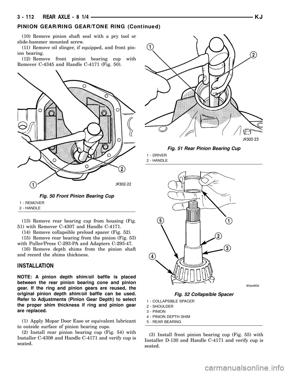
(12) Remove front pinion bearing cup with
Remover C-4345 and Handle C-4171 (Fig. 50).
(13) Remove rear bearing cup from housing (Fig.
51) with Remover C-4307 and Handle C-4171.
(14) Remove collapsible preload spacer (Fig. 52).
(15) Remove rear bearing from the pinion (Fig. 53)
with Puller/Press C-293-PA and Adapters C-293-47.
(16) Remove depth shims from the pinion shaft
and record the shims thickness.
INSTALLATION
NOTE: A pinion depth shim/oil baffle is placed
between the rear pinion bearing cone and pinion
gear. If the ring and pinion gears are reused, the
original pinion depth shim/oil baffle can be used.
Refer to Adjustments (Pinion Gear Depth) to select
the proper shim thickness if ring and pinion gear
are replaced.
(1) Apply Mopar Door Ease or equivalent lubricant
to outside surface of pinion bearing cups.
(2) Install rear pinion bearing cup (Fig. 54) with
Installer C-4308 and Handle C-4171 and verify cup is
seated.(3) Install front pinion bearing cup (Fig. 55) with
Installer D-130 and Handle C-4171 and verify cup is
seated.
Fig. 50 Front Pinion Bearing Cup
1 - REMOVER
2 - HANDLE
Fig. 51 Rear Pinion Bearing Cup
1 - DRIVER
2 - HANDLE
Fig. 52 Collapsible Spacer
1 - COLLAPSIBLE SPACER
2 - SHOULDER
3 - PINION
4 - PINION DEPTH SHIM
5 - REAR BEARING
3 - 112 REAR AXLE-81/4KJ
PINION GEAR/RING GEAR/TONE RING (Continued)