2002 JEEP LIBERTY dimensions
[x] Cancel search: dimensionsPage 724 of 1803

of the washer pump/motor unit is connected to the
front nipple.
(10) Engage the ªWº clip that secures the front
bumper fascia to the front bumper support. This clip
is located behind the bumper support and below the
right front lamp unit.
(11) Reinstall the splash shield into the right front
fender wheel house. (Refer to 23 - BODY/EXTERIOR/
WHEELHOUSE SPLASH SHIELD - INSTALLA-
TION).
(12) Lower the vehicle.
(13) Install and tighten the screw that secures the
washer reservoir filler neck support to upper radiator
crossmember (Fig. 23). Tighten the screw to 7 N´m
(65 in. lbs.).
(14) Reinstall the air cleaner housing onto the top
of the right front fender wheel house. (Refer to 9 -
ENGINE/AIR INTAKE SYSTEM/AIR CLEANER
ELEMENT - INSTALLATION).
(15) Refill the washer reservoir with the washer
fluid drained from the reservoir during the removal
procedure.
(16) Reconnect the battery negative cable.
WIPER HIGH/LOW RELAY
DESCRIPTION
The wiper high/low relay is located in the Power
Distribution Center (PDC) in the engine compart-
ment near the battery. The wiper high/low relay is a
conventional International Standards Organization
(ISO) micro relay (Fig. 25). Relays conforming to theISO specifications have common physical dimensions,
current capacities, terminal patterns, and terminal
functions. The relay is contained within a small, rect-
angular, molded plastic housing and is connected to
all of the required inputs and outputs by five integral
male spade-type terminals that extend from the bot-
tom of the relay base.
The wiper high/low relay cannot be adjusted or
repaired and, if faulty or damaged, the unit must be
replaced.
OPERATION
The wiper high/low relay is an electromechanical
switch that uses a low current input from the Body
Control Module (BCM) to control a high current out-
put to the front wiper motor. The movable common
feed contact point is held against the fixed normally
closed contact point by spring pressure. When the
relay coil is energized, an electromagnetic field is
produced by the coil windings. This electromagnetic
field draws the movable relay contact point away
from the fixed normally closed contact point, and
holds it against the fixed normally open contact
point. When the relay coil is de-energized, spring
pressure returns the movable contact point back
against the fixed normally closed contact point. A
resistor is connected in parallel with the relay coil in
the relay, and helps to dissipate voltage spikes and
electromagnetic interference that can be generated as
the electromagnetic field of the relay coil collapses.
The wiper high/low relay terminals are connected
to the vehicle electrical system through a connector
receptacle in the Power Distribution Center (PDC).
The inputs and outputs of the wiper high/low relay
include:
²Common Feed Terminal- The common feed
terminal (30) is connected to the output of the wiper
on/off relay at all times through the wiper on/off
relay output circuit.
²Coil Ground Terminal- The coil ground termi-
nal (85) is connected to a control output of the Body
Control Module (BCM) through a front wiper high/
low relay control circuit. The BCM controls front
wiper motor operation by controlling a ground path
through this circuit.
²Coil Battery Terminal- The coil battery ter-
minal (86) receives battery current at all times from
a circuit breaker in the Junction Block (JB) through
a fused ignition switch output (run-acc) circuit.
²Normally Open Terminal- The normally open
terminal (87) is connected to the high speed brush of
the front wiper motor through a front wiper high/low
relay high speed output circuit, and is connected to
the high speed brush whenever the relay is ener-
gized.
Fig. 25 ISO Micro Relay
30 - COMMON FEED
85 - COIL GROUND
86 - COIL BATTERY
87 - NORMALLY OPEN
87A - NORMALLY CLOSED
KJFRONT WIPERS/WASHERS 8R - 23
WASHER RESERVOIR (Continued)
Page 726 of 1803

WIPER ON/OFF RELAY
DESCRIPTION
The wiper on/off relay is located in the Power Dis-
tribution Center (PDC) in the engine compartment
near the battery. The wiper on/off relay is a conven-
tional International Standards Organization (ISO)
micro relay (Fig. 28). Relays conforming to the ISO
specifications have common physical dimensions, cur-
rent capacities, terminal patterns, and terminal func-
tions. The relay is contained within a small,
rectangular, molded plastic housing and is connected
to all of the required inputs and outputs by five inte-
gral male spade-type terminals that extend from the
bottom of the relay base.
The wiper on/off relay cannot be adjusted or
repaired and, if faulty or damaged, the unit must be
replaced.
OPERATION
The wiper on/off relay is an electromechanical
switch that uses a low current input from the Body
Control Module (BCM) to control a high current out-put to the front wiper motor. The movable common
feed contact point is held against the fixed normally
closed contact point by spring pressure. When the
relay coil is energized, an electromagnetic field is
produced by the coil windings. This electromagnetic
field draws the movable relay contact point away
from the fixed normally closed contact point, and
holds it against the fixed normally open contact
point. When the relay coil is de-energized, spring
pressure returns the movable contact point back
against the fixed normally closed contact point. A
resistor is connected in parallel with the relay coil in
the relay, and helps to dissipate voltage spikes and
electromagnetic interference that can be generated as
the electromagnetic field of the relay coil collapses.
The wiper on/off relay terminals are connected to
the vehicle electrical system through a connector
receptacle in the Power Distribution Center (PDC).
The inputs and outputs of the wiper on/off relay
include:
²Common Feed Terminal- The common feed
terminal (30) is connected to the common feed termi-
nal of the wiper high/low relay at all times through
the wiper on/off relay output circuit.
²Coil Ground Terminal- The coil ground termi-
nal (85) is connected to a control output of the Body
Control Module (BCM) through a front wiper on/off
relay control circuit. The BCM controls front wiper
motor operation by controlling a ground path through
this circuit.
²Coil Battery Terminal- The coil battery ter-
minal (86) receives battery current at all times from
a circuit breaker in the Junction Block (JB) through
a fused ignition switch output (run-acc) circuit.
²Normally Open Terminal- The normally open
terminal (87) receives battery current at all times
from a circuit breaker in the Junction Block (JB)
through a fused ignition switch output (run-acc) cir-
cuit, and provides battery current to the front wiper
on/off relay output circuit whenever the relay is ener-
gized.
²Normally Closed Terminal- The normally
closed terminal (87A) is connected to the wiper park
switch in the front wiper motor through the front
wiper park switch sense circuit, and is connected to
the wiper park switch whenever the relay is de-ener-
gized.
The wiper on/off relay can be diagnosed using con-
ventional diagnostic tools and methods.
Fig. 28 ISO Micro Relay
30 - COMMON FEED
85 - COIL GROUND
86 - COIL BATTERY
87 - NORMALLY OPEN
87A - NORMALLY CLOSED
KJFRONT WIPERS/WASHERS 8R - 25
Page 1326 of 1803
(2) Insufficient running time after rebuilding cylin-
der head. Low speed running up to 1 hour may be
required.
(3) During this time, turn engine off and let set for
a few minutes before restarting. Repeat this several
times after engine has reached normal operating
temperature.
(4) Low oil pressure.
(5) The oil restrictor (integral to the head gasket)
in the vertical oil passage to the cylinder head is
plugged with debris.
(6) Air ingested into oil due to broken or cracked
oil pump pick up.
(7) Worn valve guides.
(8) Rocker arm ears contacting valve spring
retainer.
(9) Rocker arm loose, adjuster stuck or at maxi-
mum extension and still leaves lash in the system.
(10) Faulty lash adjuster.
a. Check lash adjusters for sponginess while
installed in cylinder head. Depress part of rocker
arm over adjuster. Normal adjusters should feel very
firm. Spongy adjusters can be bottomed out easily.
b. Remove suspected lash adjusters, and replace as
necessary.
REMOVAL
NOTE: This procedure is for in-vehicle service with
camshafts installed.
(1) Remove cylinder head cover. (Refer to 9 -
ENGINE/CYLINDER HEAD/CYLINDER HEAD
COVER(S) - REMOVAL)
(2) Remove the camshafts (Refer to 9 - ENGINE/
CYLINDER HEAD/CAMSHAFT(S) - REMOVAL).
(3) Remove rocker arm. (Refer to 9 - ENGINE/
CYLINDER HEAD/ROCKER ARMS - REMOVAL)
(4) Remove hydraulic lifter (Fig. 30).(5) Repeat removal procedure for each hydraulic
lifter.
(6) If reusing, mark each hydraulic lifter for reas-
sembly in original position. Lifters are serviced as an
assembly.
INSTALLATION
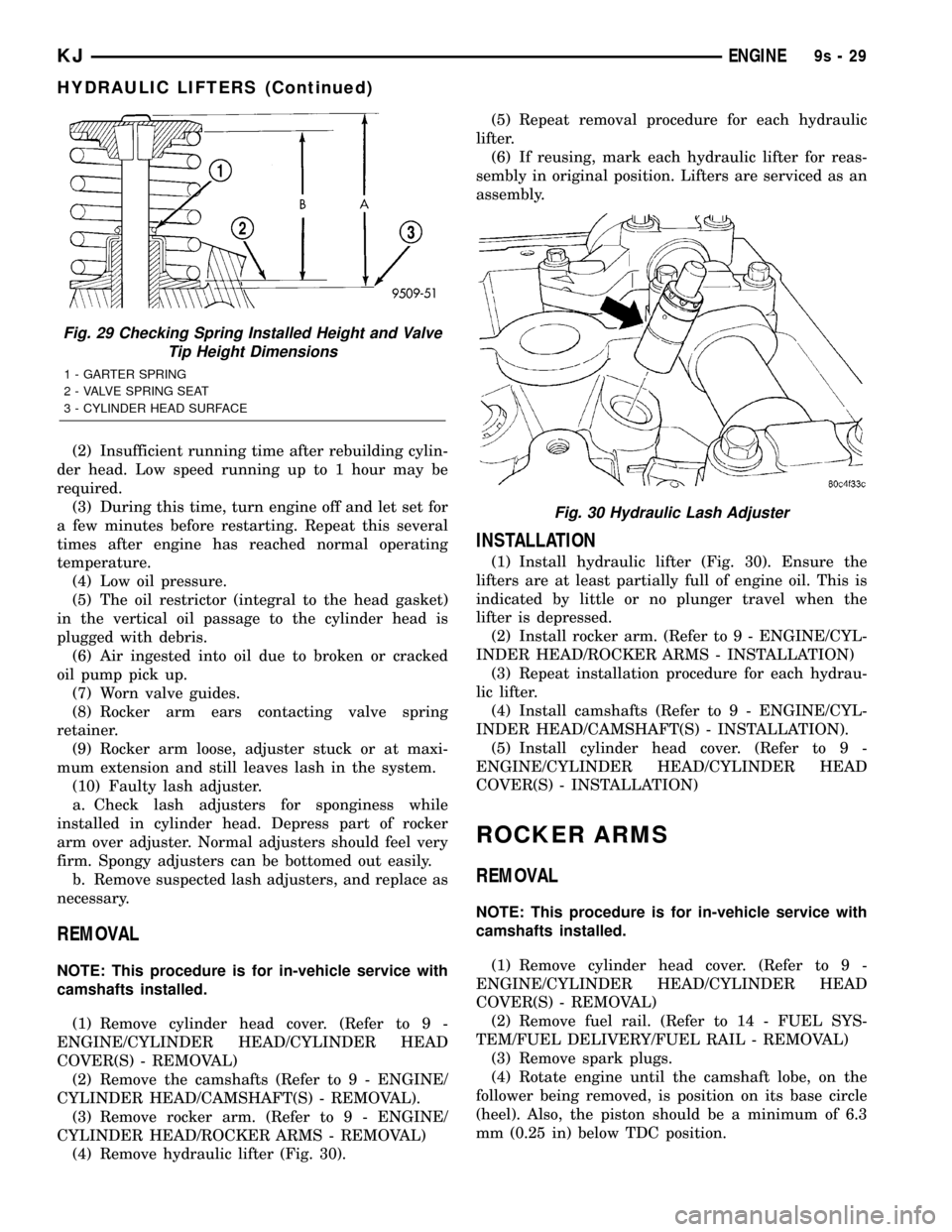
(1) Install hydraulic lifter (Fig. 30). Ensure the
lifters are at least partially full of engine oil. This is
indicated by little or no plunger travel when the
lifter is depressed.
(2) Install rocker arm. (Refer to 9 - ENGINE/CYL-
INDER HEAD/ROCKER ARMS - INSTALLATION)
(3) Repeat installation procedure for each hydrau-
lic lifter.
(4) Install camshafts (Refer to 9 - ENGINE/CYL-
INDER HEAD/CAMSHAFT(S) - INSTALLATION).
(5) Install cylinder head cover. (Refer to 9 -
ENGINE/CYLINDER HEAD/CYLINDER HEAD
COVER(S) - INSTALLATION)
ROCKER ARMS
REMOVAL
NOTE: This procedure is for in-vehicle service with
camshafts installed.
(1) Remove cylinder head cover. (Refer to 9 -
ENGINE/CYLINDER HEAD/CYLINDER HEAD
COVER(S) - REMOVAL)
(2) Remove fuel rail. (Refer to 14 - FUEL SYS-
TEM/FUEL DELIVERY/FUEL RAIL - REMOVAL)
(3) Remove spark plugs.
(4) Rotate engine until the camshaft lobe, on the
follower being removed, is position on its base circle
(heel). Also, the piston should be a minimum of 6.3
mm (0.25 in) below TDC position.
Fig. 29 Checking Spring Installed Height and Valve
Tip Height Dimensions
1 - GARTER SPRING
2 - VALVE SPRING SEAT
3 - CYLINDER HEAD SURFACE
Fig. 30 Hydraulic Lash Adjuster
KJENGINE9s-29
HYDRAULIC LIFTERS (Continued)
Page 1374 of 1803
FRAMES & BUMPERS
TABLE OF CONTENTS
page page
FRONT FASCIA
REMOVAL.............................1
INSTALLATION..........................2
REAR FASCIA
REMOVAL.............................2
INSTALLATION..........................2
REAR FASCIA SUPPORT
REMOVAL.............................3
INSTALLATION..........................3
FRAME
SPECIFICATIONS
SPECIFICATIONS - FRAME DIMENSIONS . . . 3
SPECIFICATIONS - TORQUE.............6
FRONT SKID PLATE
REMOVAL.............................6
INSTALLATION..........................6
ENGINE CRADLE CROSSMEMBER
REMOVAL.............................6
INSTALLATION..........................6TRANSFER CASE SKID PLATE
REMOVAL.............................7
INSTALLATION..........................7
REAR CROSSMEMBER
REMOVAL.............................7
INSTALLATION..........................7
FRONT TOW HOOK
REMOVAL.............................8
INSTALLATION..........................8
REAR TOW HOOK
REMOVAL.............................8
INSTALLATION..........................8
TRAILER HITCH
REMOVAL.............................9
INSTALLATION..........................9
FUEL TANK SKID PLATE
REMOVAL.............................9
INSTALLATION..........................9
FRONT FASCIA
REMOVAL
(1) Remove the grille. (Refer to 23 - BODY/EXTE-
RIOR/GRILLE - REMOVAL)
(2) Raise and support vehicle.
(3) Remove the front wheel opening flare moldings.
(Refer to 23 - BODY/EXTERIOR/FRONT WHEEL
OPENING FLARE MOLDINGS - REMOVAL)
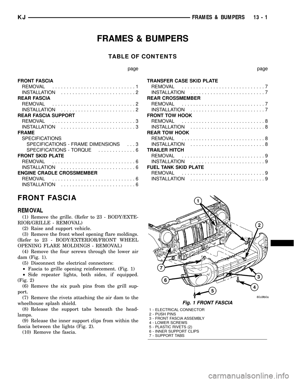
(4) Remove the four screws through the lower air
dam (Fig. 1).
(5) Disconnect the electrical connectors:
²Fascia to grille opening reinforcement. (Fig. 1)
²Side repeater lights, both sides, if equipped.
(Fig. 2)
(6) Remove the six push pins from the grill sup-
port.
(7) Remove the rivets attaching the air dam to the
wheelhouse splash shield.
(8) Release the support tabs beneath the head-
lamps.
(9) Release the inner support clips from within the
fascia between the lights (Fig. 2).
(10) Remove the fascia.
Fig. 1 FRONT FASCIA
1 - ELECTRICAL CONNECTOR
2 - PUSH PINS
3 - FRONT FASCIA ASSEMBLY
4 - LOWER SCREWS
5 - PLASTIC RIVETS (2)
6 - INNER SUPPORT CLIPS
7 - SUPPORT TABS
KJFRAMES & BUMPERS 13 - 1
Page 1376 of 1803
REAR FASCIA SUPPORT
REMOVAL
(1) Remove the rear fascia assembly. (Refer to 13 -
FRAME & BUMPERS/BUMPERS/REAR FASCIA -
REMOVAL)
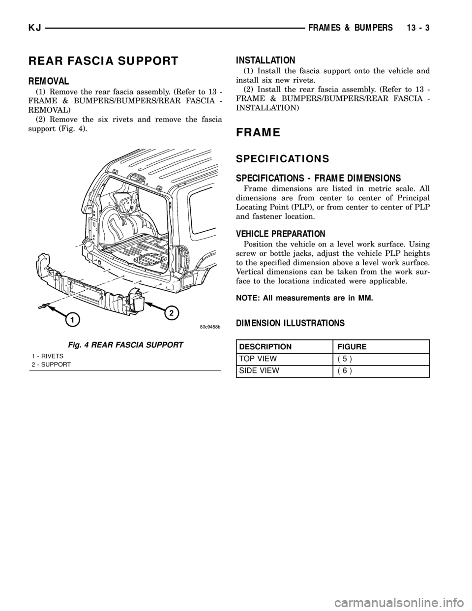
(2) Remove the six rivets and remove the fascia
support (Fig. 4).
INSTALLATION
(1) Install the fascia support onto the vehicle and
install six new rivets.
(2) Install the rear fascia assembly. (Refer to 13 -
FRAME & BUMPERS/BUMPERS/REAR FASCIA -
INSTALLATION)
FRAME
SPECIFICATIONS
SPECIFICATIONS - FRAME DIMENSIONS
Frame dimensions are listed in metric scale. All
dimensions are from center to center of Principal
Locating Point (PLP), or from center to center of PLP
and fastener location.
VEHICLE PREPARATION
Position the vehicle on a level work surface. Using
screw or bottle jacks, adjust the vehicle PLP heights
to the specified dimension above a level work surface.
Vertical dimensions can be taken from the work sur-
face to the locations indicated were applicable.
NOTE: All measurements are in MM.
DIMENSION ILLUSTRATIONS
DESCRIPTION FIGURE
TOP VIEW ( 5 )
SIDE VIEW ( 6 )Fig. 4 REAR FASCIA SUPPORT
1 - RIVETS
2 - SUPPORT
KJFRAMES & BUMPERS 13 - 3
Page 1471 of 1803
BODY STRUCTURE
TABLE OF CONTENTS
page page
ASSEMBLY
SPECIFICATIONS
SPECIFICATION.......................6
WELD AND STRUCTURAL ADHESIVE
LOCATIONS
SPECIFICATIONS........................9SEALER LOCATIONS
SPECIFICATIONS.......................87
OPENING DIMENSIONS
SPECIFICATIONS......................111
GAP AND FLUSH
SPECIFICATIONS......................116
ASSEMBLY
SPECIFICATIONS
SPECIFICATION
INDEX
DESCRIPTION FIGURE
COMPLETE BODY STRUCTURE VIEWS ( 1 )
BODY STRUCTURE - SECTIONS ( 2 )
23 - 6 BODY STRUCTUREKJ
Page 1576 of 1803
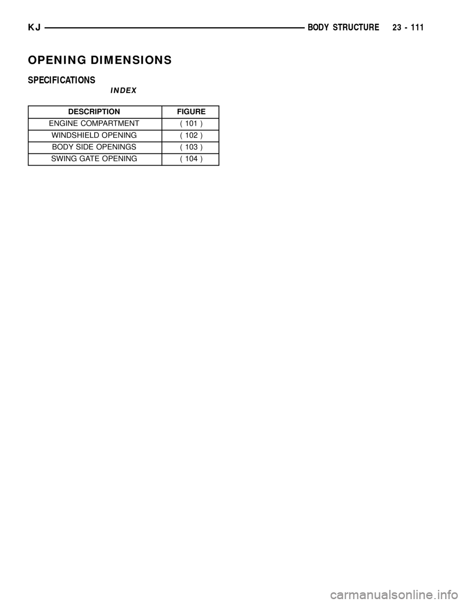
OPENING DIMENSIONS
SPECIFICATIONS
INDEX
DESCRIPTION FIGURE
ENGINE COMPARTMENT ( 101 )
WINDSHIELD OPENING ( 102 )
BODY SIDE OPENINGS ( 103 )
SWING GATE OPENING ( 104 )
KJBODY STRUCTURE 23 - 111
Page 1577 of 1803

Fig. 101 ENGINE COMPARTMENT
23 - 112 BODY STRUCTUREKJ
OPENING DIMENSIONS (Continued)